COMPLIANCE STATEMENTS
INDUSTRIAL CANADA EMISSION COMPLIANCE STATEMENTS
This device complies with Industry Canada license-exempt RSS standards
RSS 139 and RSS 210. Operation is subject to the following two conditions:
(1) this device may not cause interference, and (2) this device must accept
any interference, including interference that may cause undesired
operation of the device.
This Class B digital apparatus complies with Canadian ICES-003.
Le présent appareil est conforme aux CNR d’Industrie Canada applicables
aux appareils radio exempts de licence. L’exploitation est autorisée aux deux
conditions suivantes : (1) l’appareil ne doit pas produire de brouillage, et (2)
l’utilisateur de l’appareil doit accepter tout brouillage radioélectrique subi,
même si le brouillage est susceptible d’en compromettre le
fonctionnement.Cet appareil numérique de la classe B est conforme à la
norme NMB-003 du Canada.
FEDERAL COMMUNICATIONS COMMISSION (FCC) STATEMENTS
This equipment has been tested and found to
comply with the limits for a Class B digital device,
pursuant to part 15 of the FCC Rules. These limits
are designed to provide reasonable protection
against harmful interference in a residential
installation. This equipment generates, uses and
can radiate radio frequency energy and, if not
installed and used in accordance with the instructions, may cause harmful
interference to radio communications. However, there is no guarantee that
interference will not occur in a particular installation. If this equipment does
cause harmful interference to radio or television reception, which can be
determined by turning the equipment off and on, the user is encouraged
to try to correct the interference by one or more of the following
measures:
Reorient or relocate the receiving antenna.
Increase the separation between the equipment and receiver.
Connect the equipment into an outlet on a circuit different from that
to which the receiver is connected.
Consult the dealer or an experienced radio/TV technician for help.
In order to maintain compliance with FCC regulations, shielded cables must
be used with this equipment. Operation with non-approved equipment or
unshielded cables is likely to result in interference to radio and TV
reception. The user is cautioned that changes and modifications made to
the equipment without the approval of manufacturer could void the users
authority to operate this equipment.
NOTE: This device complies with Part 15 of the FCC Rules.
Operations subjected to the following two conditions (1) this device may
not cause harmful interference, and (2) this device must accept any
interference received, including that may cause undesirable interference.
CAUTION: Exposure to Radio Frequency Radiation.
The device shall be used in such a manner that the potential for human
contact is minimized.
C OP YRIGHT © 201 7 P AN A VISION IN TER N A TION A L, L .P . FW : V-0.5.35| 4
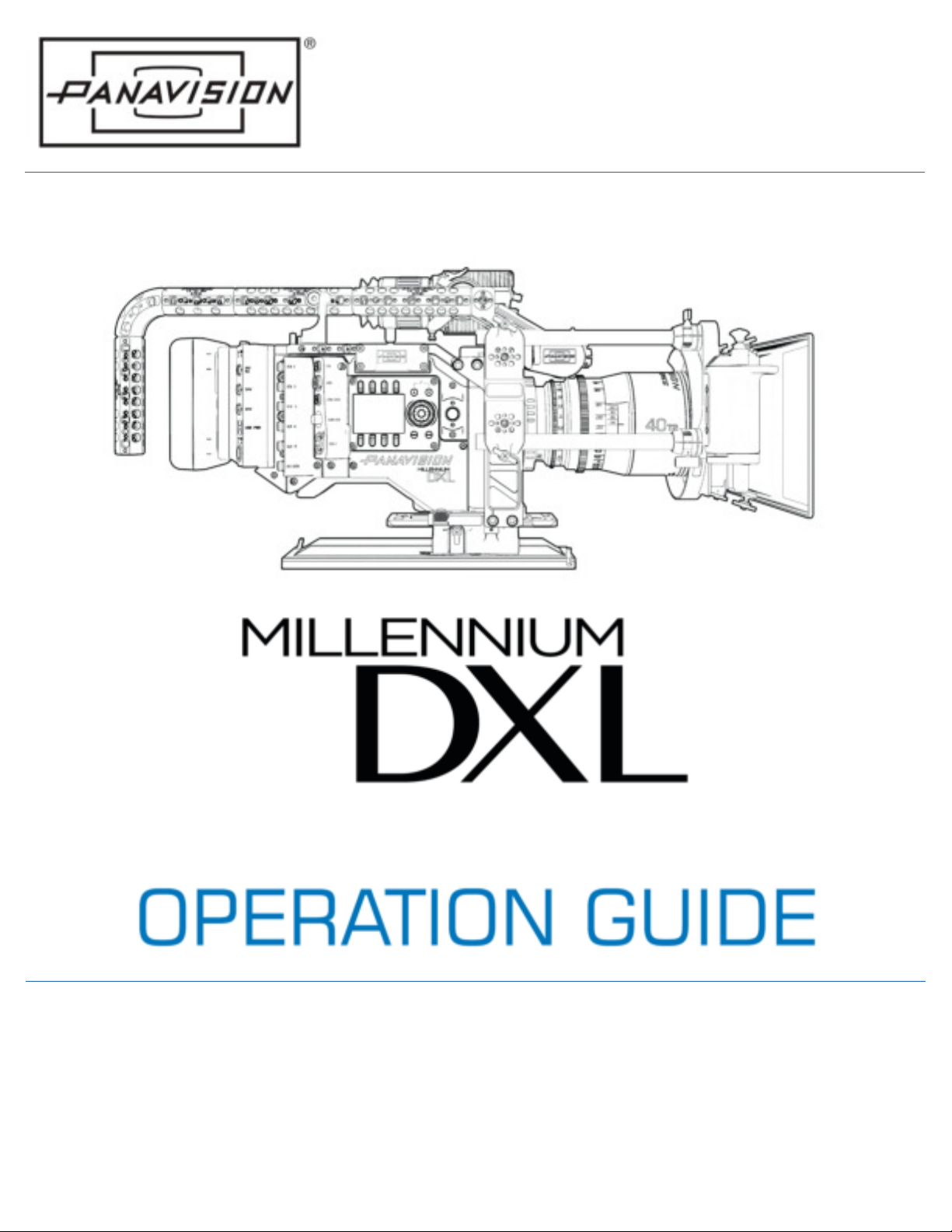
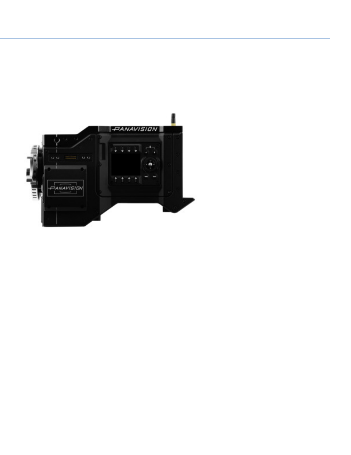
PANAVISION MILLENNIUM DXL
This equipment complies with FCC radiation exposure limits set forth for an
uncontrolled environment. This equipment should be installed and
operated with a minimum distance of 20 cm between the radiator and
your body.
CAUTION: Regulations of the FCC and FAA prohibit
airborne operation of radio- frequency wireless
devices because there signals could interfere with
critical aircraft instruments.
CAUTION: If the device is changed or modified
without permission, the user may void his or her
authority to operate the equipment.
AUSTRALIA AND NEW ZEALAND STATEMENTS
Panavision declares that the radio equipment described in this document
comply with the following international standards.
IEC 60065 – Product Safety
ETSI EN 300 328 – Technical requirement for radio equipment
Panavision declares digital devices described in this document comply with
the following Australian and New Zealand standards.
AS/NZS CISPR 22 – Electromagnetic Interference
AS/NZS 61000.3.2 – Power Line Harmonics
AS/NZS 61000.3.3 – Power Line Flicker
JAPAN STATEMENTS
This is a Class B product based on the
standard of the Voluntary Control Council for
Interference (VCCI) for information technology
equipment. If this equipment is used near a
radio or television receiver in a domestic
environment, it may cause radio interference.
Install and use the equipment according to the
instruction manual.