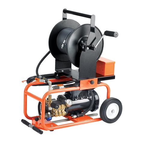
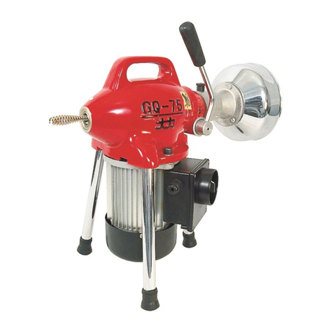
Panblast Tornado User manual

PRODUCTOPERATINGMANUAL
PANBLASTTM
TORNADOINTERNALPIPEBLASTINGTOOL
ManualNumber:ZVP‐PC‐0068‐00

SECTION
1. GENERAL INFORMATION
2. INTRODUCTION
3. INITIAL SETUP INSTRUCTIONS
4. OPERATING INSTRUCTIONS
5. MAINTENANCE
6. TROUBLE SHOOTING GUIDE
7. ASSEMBLIES, PARTS LISTING & EXPLODED VIEW

- 1 –
ZVP-PC-0068-00-R2
1.0 GENERAL INFORMATION
1.1 Panblast notice to purchasers and users
1.1.1 All products and equipment designed and
manufactured by Panblast are intended for use
by experienced users of abrasive blasting
equipment and its associated operations and
abrasive blasting media.
1.1.2 It is the responsibility of the user to:
- Determine if the equipment and abrasive
media are suitable for the users' intended
use and application.
- Familiarize themselves with any appropriate
laws, regulations and safe work practices,
which may apply within the users working
environment.
- Provide appropriate operator training and a
safe working environment including
operator protective equipment such as, but
not limited to, safety footwear, protective
eyewear and hearing protection.
1.1.3 Panblast Standard Terms and Conditions of Sale
apply. Contact your local Panblast office should
you require any further information or
assistance.
1.2 ! WARNING! – READ THIS SECTION
CAREFULLY BEFORE USING THIS
EQUIPMENT/APPARATUS.
1.2.1 Heavy metal paint, asbestos and other toxic
material dusts will cause serious lung disease or
death without the use of properly designed and
approved supplied air respiratory equipment
(SAR) by blast operators and all personnel within
the work site area.
1.2.2 The compressor must have adequate output and
the plumbing between the compressor and the
point of attaching the air supply hose must have
sufficient capacity to supply the volume of air at
the pressure required.
1.3 Standard safety precautions
1.3.1 Approved safety eyewear, hearing and footwear
protection should be worn at all times by the
operator and anyone else in the immediate area
that may be exposed to any hazards generated
by the abrasive blasting process.
1.3.2 Suitably approved respiratory protection should
also be worn when handling abrasive media,
abrasive refuse dust and when carrying out any
service/maintenance work where any dust may
be present.
1.3.3 Any work performed on electrical wiring or
components must only be carried out by
suitably qualified and registered electrical trades
personnel.
1.3.4 Under no circumstances should any safety
interlocks / lockouts or features be altered or
disabled in any way.
1.3.5 All equipment must be isolated from the
compressed air supply and electrical power prior
to any service or maintenance work being
carried out.
1.3.6 All care must be taken by the operator(s) when
lifting or moving equipment or components in
order to prevent injury. Blast pots must always
be emptied of abrasive media before any
attempt is made to move them.
1.3.7 Any modification of the equipment and/or
components or use of non-genuine PanBlast™
replacement parts will void warranty.
1.3.8 Always check the Material Safety Data Sheet
(MSDS) on the abrasive media being used to
ensure that it is free of harmful substances, in
particular, free silica, cyanide, arsenic or lead.
1.3.9 Test the surface that is to be blasted for harmful
substances, taking the appropriate measures to
ensure the safety of the operator and others.
1.3.10 The operator should carry out a daily inspection
of all related components prior to startup of all
wearing and safety items to ensure they are in
correct operating order. In particular check all
hose couplings and nozzle holders, ensuring
that all hose couplings are fitted correctly, the
safety locking pins are engaged and in good
order. Always install safety whip check cables at
every hose connection. Ensure that the blast
nozzle has been securely screwed into the
nozzle holder and the nozzle holder has been
secured to the blast hose correctly and all
screws are engaged.
NOTE: UNDER OSHA 1915:34(c)(1)(iv) DEAD
MAN CONTROL. A DEADMAN CONTROL
DEVICE SHALL BE PROVIDED AT THE NOZZLE
END OF THE BLAST HOSE EITHER TO PROVIDE
DIRECT CUTOFF OR TO SIGNAL THE POT
TENDER BY MEANS OF A VISUAL AND
AUDIBLE SIGNAL TO CUT OFF THE FLOW, IN
THE EVENT THE BLASTER LOSES CONTROL OF
THE HOSE. THE POT TENDER SHALL BE
AVAILABLE AT ALL TIMES TO RESPOND
IMMEDIATELY TO THE SIGNAL.
2.0 INTRODUCTION
2.1 The Tornado Internal Pipe Blasting Tool Set is
designed to clean the internal surfaces of pipes
from 200mm (8”) to 900mm (36”) I.D.The tool
is connected to a pipe lance that is coupled to a
standard blast hose in place of the blast nozzle.
A carriage fitted to the tool supports the tool
and centers it within the pipe, the tool is
positioned at the far end of the pipe and slowly
withdrawn, as the tool travels down the pipe
abrasive media is thrown from a twin nozzle
rotating blast head. The speed of the rotating
head is controlled by a centrifugal speed limiter.
There are three types of centering carriages
available to suit small, medium and large
diameter pipes.
Refer to the charts below for the centering
carriage assemblies, blast nozzles and air
requirements to suit various applications.
- 2 –
ZVP-PC-0068-00-R2
2.2 Application table
Pipe
I.D.
Nozzle
Sizes
Rotating
Head
Carriage
Selection
Compressed
Air
Requirement
200mm
(8")
300mm
(12")
ATN-4S
6.4mm
(1/4")
Small
Small
Range
scissor
6.37m³/min
225 cfm
300mm
(12")
500mm
(20")
ATN-5T
8mm
(5/16")
Small
Mid
Range
10.6m³/min
375 cfm
600mm
(24")
915mm
(36")
ATN-6T
9.5mm
(3/8”)
Small
Mid
Range
15.3 m³/min
540 cfm
1015m
m (40")
1525m
m (60")
UTN-6
9.5mm
(3/8")
Large
Large
Range
15.3 m³/min
540 cfm
Table 2.2
NOTE: FOR PRATICAL PURPOSES WE RECOMMEND A
MINIMUN COMPRESSED AIR SUPPLY OF AT LEAST 50%
HIGHER THAN THE NOZZLE REQUIREMENT LISTED
ABOVE.
! WARNING! – ENSURE THAT THE BLAST NOZZLE
SELECTION IS MATCHED TO THE COMPRESSED AIR
VOLUME AS PER TABLE 2.2 - THE USE OF UNDERSIZED
NOZZLES WILL SEVERELY DAMAGE THE TORNADO
TOOL.
2.3 Abrasive recommendations
The following list recommends the maximum abrasive
sizes to be used with the Tornado Internal Pipe Blasting
Tool Set
Garnet #20/40
Steel Grit SAE G25
Steel Shot SAE S230
Chilled Iron Grit BSS G34
Table 2.3
3.0 INITIAL SET UP INSTRUCTIONS
3.1 The Tornado Internal Pipe Blasting Tool Set
requires the same basic blast equipment as any
other abrasive blast blasting operation, utilizing
an air compressor and abrasive blast pot system,
the difference being that the blast nozzle is
replaced by the Tornado tool, carriage system
and pipe lance. The lance (customer supply)
should be the same length as the pipe to be
blast cleaned. Two (2) PanBlast™ NTC-1
Threaded Couplings (BAC-HC-PB-0009) are
supplied to fit the lance to the Tornado tool and
an existing blast hose coupling.
3.2 Check the compressed air requirement for the
appropriate blast nozzles to suit your
application, the standard Tornado tool is
supplied with 2 x ATN-4S 6.4mm (1/4”)
tungsten carbide blast nozzles as standard,
ensure you have adequate compressed air
capacity for your application.
! WARNING! – NEVER EXCEED THE
MAXIMUM OPERATING PRESSURE OF 150PSI
(10.4BAR), AS THIS MAY RESULT IN SERIOUS
INJURY OR DEATH.
3.3 The Tornado tool is also supplied standard with
the 19mm 3/4" small BSP/NPSM Rotating Head
(BAC-BA-0134-00) that suits the PanBlast™ Fine
Thread Series ATN-S Nozzles. Should it be
necessary to run the coarse thread long venturi
UTN blast nozzles it is necessary to run these
nozzles with the 2" Tornado Large Rotating
Head Assembly, BAC-BA-0206-00.
NOTE: IN ORDER TO RUN THE LONG VENTURI
COARSE THREAD BLAST NOZZLES WITH THE
LARGE ROTATING HEAD A MINIMUM PIPE
INTERNAL DIAMETER OF 1015 MM (40”) IS
RECOMMENDED.
! WARNING! – THE ROTATING HEADS ARE
DESIGNED TO BE USED WITHOUT RUBBER
NOZZLE WASHERS. ONLY USE THREAD
SEALANT FOR THREAD SEALING BETWEEN
THE NOZZLE THREADS AND THE ROTATING
HEAD THREADS. THE USE OF NOZZLE
WASHERS, OR MODIFICATIONS TO THE
ROTATING HEAD, MAY RESULT IN TOOL
MALFUNCTION OR SHORTENED TOOL LIFE.
3.4 Fitting of the small range scissor carriage
3.4.1 Slide the back end of the Tornado tool into the
expanded carriage, through the front collar and
into the rear collar, the rear collar should be
located in front of the breather vent holes on
the seal retainer body, do not block the vent
holes. Now tighten the two (2) set screws on the
rear collar.
Figure a
! WARNING! – IF THE REAR COLLAR BLOCKS
OR OBSTRUCTS THE VENT HOLES, IT WILL
CAUSE SEVERE WEAR ON THE FLANGE WEAR
SLEEVE AND DAMAGE THE INTERNAL SEAL
AND BEARINGS.
3.4.2 Adjust the carriage to suit the internal diameter
of the pipe by expanding the carriage scissor
mechanism and tighten the two (2) socket set
screws on the front collar.
3.4.3 Check that the rotating head spins freely.
3.5 Fitting the large and mid range carriages
3.5.1 The large and medium range carriages are each
supplied with a front carriage body, a rear lance
carriage body and appropriate leg assemblies
for varying pipe I.D.'s.
3.5.2 Slide the back end of the Tornado tool into the
larger front carriage body, position the front of
the body flush with the front face of the
centrifugal speed limiter housing, ensure that
the body is located in front of the breather vent
holes on the seal retainer body, do not block
VentHoles

- 3 –
ZVP-PC-0068-00-R2
the vent holes. Now tighten the two (2) screws
on the body to fix the body to the tool.
Figure b
! WARNING! – IF THE BODY OF THE
CARRIAGE BLOCKS OR OBSTRUCTS THE VENT
HOLES, IT WILL CAUSE SEVERE WEAR ON THE
FLANGE WEAR SLEEVE AND DAMAGE THE
INTERNAL SEAL AND BEARINGS.
3.5.3 Fit the smaller rear lance carriage body to the
lance pipe which should be positioned to
prevent excess bowing of the lance pipe and
angular misalignment of the coupled
connections.
3.5.4 Now fit the appropriate leg assemblies to the
front carriage body and rear lance carriage body,
adjust so that the Tornado tool and the lance
are centered within the pipe, and also check that
the wheel assemblies are in line with the
direction of travel.
NOTE: THE LARGE AND MID-RANGE
CARRIAGES TRACK BEST WHEN SET UP IN A
“Y” CONFIGURATION, ONE LEG POINTING
DOWN.
3.6 Fitting of the pipe lance to the tool
3.6.1 Fit the NTC-1 nylon threaded pot coupling (BAC-
HC-PB-0009) to the rear entry nozzle of the
Tornado tool.
3.6.2 Fit the second NTC-1 threaded coupling to the
end of the pipe lance. Ensure that the lance has
32mm 11/4” BSP (T) threads cut on both ends.
3.6.3 Couple the lance to the Tornado tool ensuring
that the coupling safety pins are properly
connected and secure.
3.6.4 Fit the third NTC-1 threaded coupling to the
other end of the lance.
3.6.5 Now couple the blast hose to the supply end of
the pipe lance, the blast hose will require the
removal of the nozzle holder and the fitting of
an appropriate nylon blast hose coupling to suit
the blast hose. Ensure that the coupling safety
pins are properly connected and secure.
4.0 OPERATING INSTRUCTIONS
4.1 Push the Tornado tool and lance assembly to
the far end of the pipe to be abrasive blasted.
4.2 Now start the blast operation, a rich abrasive
feed is preferable to a lean abrasive feed.
4.3 Retract the lance back at a steady and even
speed; the speed of the retrieval determines the
surface finish and coverage achieved.
4.4 Continue with the blasting process until the
lance has been fully retracted, we recommend
the use of a docking pipe section to ensure the
full length of the pipe can be cleaned and the
lance safely extracted, docked and then turned
off.
5.0 MAINTENANCE INSTRUCTIONS
5.1 Flanged wear sleeve
5.1.1 Uncouple the Tornado tool and carriage
assembly from the lance.
5.1.2 Remove the Tornado tool from the carriage.
5.1.3 Remove the four (4) screws holding the rear
base assembly to the body.
5.1.4 Remove the rear base assembly from the
Tornado tool body.
5.1.5 Check the front wearing face of the flanged
wear sleeve for heavy grooving and abrasive
particles embedded in the face, change if either
is evident.
5.1.6 Check that the sleeve moves freely in and out in
the base housing recess, remove and blow out
any dust that may have built up.
5.1.7 Visually check the spring to ensure it is in
working order.
5.2 Entry nozzle
5.2.1 Follow steps 5.1.1-5.1.3
5.2.2 Untighten the rear 32mm (11/4”) lock nut and
then unscrew the entry nozzle from the base.
5.2.3 Inspect the entry nozzle for wear at the
discharge end, and change if worn to less than a
2mm (3/32”) wall thickness.
5.2.4 Check the condition of the rear sealing washer,
replace if damaged.
5.2.5 Reassemble.
5.3 Rear seal assembly
5.3.1 Follow steps 5.1.1-5.1.3
5.3.2 Remove the seal retainer.
5.3.3 The rear U seal and felt seal are located in the
seal retainer.
5.3.4 Remove both seals, it is advisable to change
both seals if either is worn.
5.3.5 Clean the outer face of the rear bearing of any
dust residue before reassembly.
5.4 Centrifugal speed limiter housing assembly
5.4.1 Using a spanner to hold the spindle tube at the
two flats located behind the rotating head,
unscrew the rotating head from the spindle tube.
5.4.2 Unscrew the four (4) retaining screws holding
the centrifugal speed limiter housing.
! WARNING! – THE CENTRIFUGAL SPEED
LIMITER HOUSING CAN BECOME VERY HOT IF
VentHoles

- 4 –
ZVP-PC-0068-00-R2
THE UNIT HAS BEEN RUNNING FOR ANY
LENGTH OF TIME, USE HEAT RESISTANT
GLOVES WHEN WORKING ON THE
CENTRIFUGAL SPEED LIMITER.
5.4.3 Remove the centrifugal speed limiter housing.
5.4.4 Inspect the centrifugal speed limiter brake shoe
linings for wear and ensure that both brake
shoes pivot freely, replace the brake shoes if
worn.
5.4.5 Inspect the internal braking surface of the
housing for grooving and machine or replace if
badly grooved.
5.4.6 Check the front U seal and felt seal while the
centrifugal speed limiter assembly is dismantled,
it is advisable to change both seals if either is
worn.
5.4.7 Clean the outer face of the front bearing of any
dust residue.
5.4.8 Reassemble.
5.5 Spindle tube and bearings
5.5.1 Remove both the rear base and seal retainer
assembly and the centrifugal speed limiter
housing assembly.
5.5.2 Remove the rear circlip.
5.5.3 Drive or press the spindle tube forward through
the body.
5.5.4 Extract or pull the bearings from the body.
5.5.5 Reassemble.
6.0 TROUBLE SHOOTING GUIDE
6.1 Rotating nozzle head will not rotate or
rotates slowly.
6.1.1 Insufficient air pressure, check supply.
6.1.2 Blocked blast nozzles, inspect and clear
obstruction.
6.1.3 Flanged wear sleeve has abrasive particles
embedded, remove and replace.
6.1.4 Damaged bearings, replace bearings.
6.1.5 Check rear compression spring, if damaged
replace.
6.2 Rotating nozzle head rotates too fast.
6.2.1 Centrifugal speed limiter brake shoes are worn
out, replace.
6.2.2 Check rear compression spring, if damaged
replace.
6.3 Vibration
6.3.1 One blast nozzle is plugged, inspect and clear.
6.3.2 Blast nozzles out of balance, i.e. one nozzle has
worn more than the other or blast nozzles are
not of the same type, inspect and replace.
6.3.3 Tornado tool is loose in the carriage, inspect
and tighten.

- 5 –
ZVP-PC-0068-00-R2
7.0 ASSEMBLIES, PARTS LISTING & EXPLODED VIEW
7.1 Tornado Internal Pipe Blasting Tool Set Assembly
Stock Code Description Weight
BAC-BA-0170-00 Tornado Internal Pipe Blasting Tool Set 6.15Kg (13.5lbs)
7.1.1 Tornado Internal Pipe Blasting Tool Set Parts Listing
Item Stock Code Description Qty
1 YAC-BA-0195-00 Tube 1
2 YAC-BA-0217-00 Limiter Housing 1
3 YAC-FN-0366-00 Screw 2
4 YAC-BA-0218-00 Limiter Shoe 1 PR
5 YAC-BA-0219-00 Support Ring 1
6 YAC-BA-0191-00 Bearing 2
7 YAC-BA-0192-00 Body 1
8 YAC-FN-0321-00 Circlip 2
9 YAC-BA-0189-00 Felt Seal 2
10 YAC-BA-0208-00 U Seal 2
11 YAC-BA-0207-00 Seal Retainer 1
12 YAC-BA-0228-00 Base 1
13 YAC-FN-0365-01 Dowel Pin 1
14 YAC-BA-0184-01 Lock Ring 1
15 YAC-BA-0196-01 Entry Nozzle 1
16 YAC-BA-0197-00 Sealing Washer 1
17 YAC-BA-0199-00 Wear Sleeve 1
18 YAC-BA-0198-00 Spring 1
19 YAC-FN-0367-00 Screw 2
20 YAC-PF-0352-00 NPT Plug 1
21 BAC-NZ-PB-0055 Blast Nozzle ATN-4S Alum/Tungsten Short 2
22 BAC-BA-0134-00 19mm 3/4" Small BSP/NPSM Rotating Head 1
23 YAC-FN-0368-00 Screw 4
24 YAC-FN-PB-0038 Flat Washer 8
25 YAC-FN-PB-0051 Spring Washer 8
26 YAC-FN-0369-00 Screw 4
27 BAC-HC-PB-0009 NTC-1 Nylon Threaded Pot Coupling 2
28 BAC-BA-0151-00 Tornado Small Range Scissor Carriage (Optional) 1
29 BAC-BA-0164-00 Tornado Mid Range Carriage Set (Optional) 1
30 BAC-BA-0165-00 Tornado Large Range Carriage Set (Optional) 1
31 BAC-BA-0206-00 2" Tornado Large Rotating Head Assembly (Optional) 1
32 BAC-NZ-0478-01 Blast Nozzle ATN-5T Aluminum/Tungsten (Optional) 2
33 BAC-NZ-0482-01 Blast Nozzle ATN-6T Aluminum/Tungsten (Optional) 2
34 BAC-NZ-PB-0003 Blast Nozzle UTN-6 Urethane/Tungsten (Optional) 2
7.1.2 Tornado Internal Pipe Blasting Tool Set Service Kit
Stock Code Description
BAC-BA-0220-00 Tornado Front End Service Kit - Includes Items: 3(2 Off), 4, 5, 9, 10, 19(2 Off), 23(4 Off),
24(4 0ff), 25(4 Off)
BAC-BA-0221-00 Tornado Rear End Service Kit - Includes Items: 9, 10, 16, 17, 18, 24(4 Off), 25(4 Off),
26(4 Off)

- 6 –
ZVP-PC-0068-00-R2
7.1.3 Tornado Internal Pipe Blasting Tool Set Exploded View

- 7 –
ZVP-PC-0068-00-R2
7.2 Tornado Internal Pipe Blasting Tool Set - Carriage Set Assemblies
Stock Code Description Weight
BAC-BA-0151-00 Tornado Small Range Scissor Carriage (Item 6) 3.15 Kg (7.0 lbs)
BAC-BA-0164-00 Tornado Mid Range Carriage Set (Items 1, 2, 4, 5) 9.10 Kg (20.0 lbs)
BAC-BA-0165-00 Tornado Large Range Carriage Set (Items 1, 3, 4, 5) 9.60 Kg (21.16 lbs)
7.2.1 Tornado Internal Pipe Blasting Tool Set - Carriage Set Part List
Item Stock Code Description Qty
1 YAC-BA-0168-00 Front Body 1
2 BAC-BA-0166-00 Tornado Mid Range Legs Set 1 SET
3 BAC-BA-0167-00 Tornado Large Range Legs Set 1 SET
4 YAC-BA-0169-00 Rear Body 1
5 YAC-FN-PB-0225 Screw 10
7.2.2 Tornado Internal Pipe Blasting Tool Set - Carriage Set Exploded View

- 8 –
ZVP-PC-0068-00-R2
7.3 Tornado Internal Pipe Blasting Tool Set- Large Rotating Head Assembly
Stock Code Description Weight
BAC-BA-0206-00 2" Tornado Large Rotating Head Assembly 0.80kg (1.76lbs)
7.3.1 Tornado Internal Pipe Blasting Tool Set- Large Rotating Head Parts List
Item Stock Code Description Qty
1 BAC-BA-0133-00 50mm 2" Contractor Large Rotating Head 1
2 YAC-FN-0319-00 Screw 2
7.3.2 Tornado Internal Pipe Blasting Tool Set Large Rotating Head Exploded View

- 9 –
ZVP-PC-0068-00-R2
7.4 ATN-T Blast Nozzle Assemblies
Stock Code Description Orifice Length Weight
BAC-NZ-0478-01 Blast Nozzle ATN-5T Aluminum/Tungsten
8mm (5/16”) 75mm (3”) 0.24kg (0.93lbs)
BAC-NZ-0482-01 Blast Nozzle ATN-6T Aluminum/Tungsten
9.5mm (3/8”) 100mm (4”) 0.36kg (0.80lbs)
7.4.1 ATN-T Blast Nozzle Exploded View

- 10 –
ZVP-PC-0068-00-R2
7.5 UTN-6 Blast Nozzle Assembly
Stock Code Description Orifice Length Weight
BAC-NZ-PB-0003 Blast Nozzle UTN-6 Urethane/Tungsten
9.5mm (3/8”) 178mm (7”) 0.90kg (1.98lbs)
7.5.1 UTN-6 Blast Nozzle Parts List
Item Stock Code Description Qty
1 YAC-NZ-PB-0045 Nozzle Tungsten Carbide UTN-6 1
2 BAC-NZ-PB-0031 RNW-32 Nozzle Washer – 10 Pcs 1
7.5.2 UTN-6 Blast Nozzle Exploded View
Table of contents