manuals.online logo
Brands
  1. Home
  2. •
  3. Brands
  4. •
  5. Parasound
  6. •
  7. Amplifier
  8. •
  9. Parasound P/SP-1000 User manual

Parasound P/SP-1000 User manual

-1-
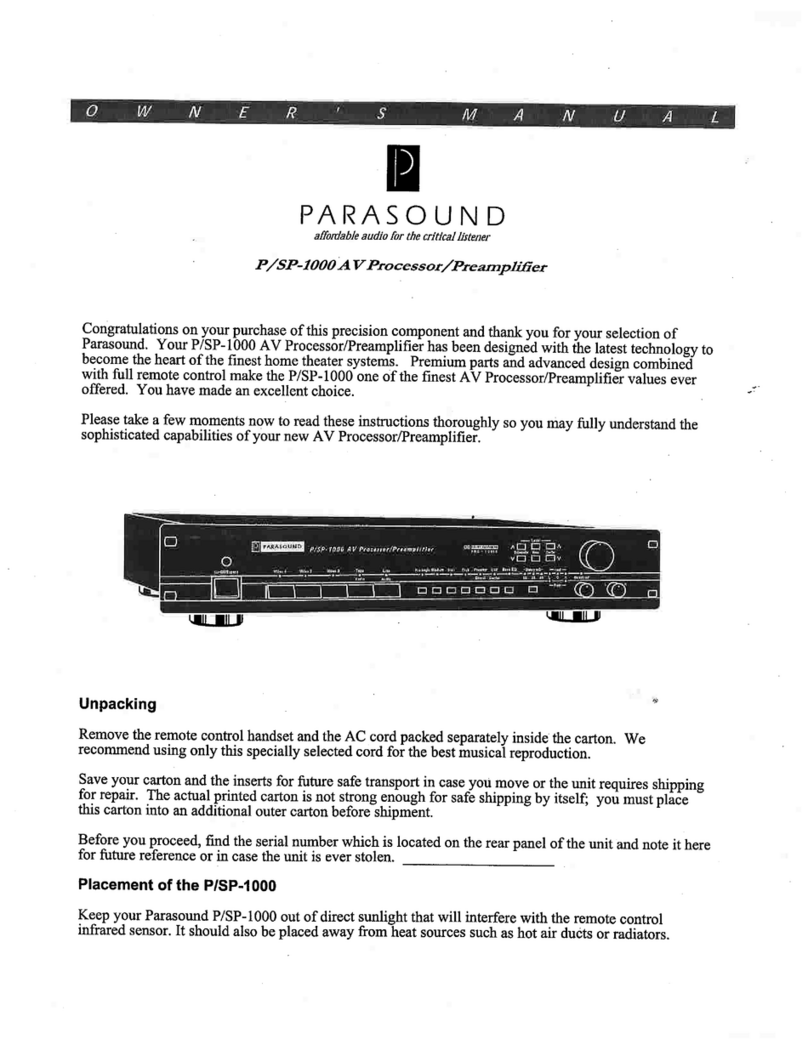
Unpacking
Remove the remote control handset and the AC cord packed separately inside the carton. We
recommend using only this specially selected cord for the best musical reproduction.
Save your carton and the inserts for future safe transport in case you move or the unit requires shipping
for repair. The actual printed carton is not strong enough for safe shipping by itself; you must place
this carton into an additional outer carton before shipment.
Before you proceed, find the serial number which is located on the rear panel of the unit and note it here
for future reference or in case the unit is ever stolen. ____________________
Placement of the P/SP-1000
Keep your Parasound P/SP-1000 out of direct sunlight that will interfere with the remote control
infrared sensor. It should also be placed away from heat sources such as hot air ducts or radiators.
Congratulations on your purchase of this precision component and thank you for your selection of
Parasound. Your P/SP-1000 AV Processor/Preamplifier has been designed with the latest technology to
become the heart of the finest home theater systems. Premium parts and advanced design combined
with full remote control make the P/SP-1000 one of the finest AV Processor/Preamplifier values ever
offered. You have made an excellent choice.
Please take a few moments now to read these instructions thoroughly so you may fully understand the
sophisticated capabilities of your new AV Processor/Preamplifier.
affordable audio for the critical listener
P/SP-1000 AV Processor/Preamplifier
O W N E R ' S M A N U A L
P/SP-1000 AV Processor/Preamplifier
On-Off/Bypass
On-Off/Bypass Video1
Video 1 Video2
Video 2 Video3
Video 3
Pro LogicPro Logic Stadium
Hall
Hall Club
Club Preamp
Preamp USF
USF
Direct
Direct Center
Center 15
15 20
20 30
30 LCROverload
Overload
BassEQ
Bass EQ DelaymS
Delay mS test
test
Subwoofer
Subwoofer RearRear
Level
Level
CenterCenter
Rear
Rear LR
Tape
Tape Line
Line
Audio
Audio Audio
Audio
PRO- LOGIC
PRO - LOGIC
DOLBY SURROUND
-2-
Input Connections to Your P/SP-1000
Refer to Drawing # 1
Before making any connections, make sure your P/SP-1000’s power is off and its volume control is
turned fully counterclockwise. Also, make sure the power is turned off to your power amplifiers. After
making connections, make sure there is no strain or tension on any wires that could cause them to pull
loose later on.
Audio/Video Input Connections
Your P/SP-1000 comes equipped with three audio/video inputs and two audio-only inputs. The audio
inputs are compatible with any typical analog line level source such as a CD player, D-A converter,
tuner, DAT, cassette deck, or the audio output of a laser disc player or VCR. The three audio/video
inputs also have switching capability for both NTSC composite and S-Video. Two of the A/V
connections and one of the audio-only inputs also provide recording capability. You may also use just
the audio sections of the A/V inputs if you wish.
LD Input (Play Only)
Connect the audio and video outputs of any audio/video source such as a laser disc player to this input.
The LD input accepts either S-Video or NTSC composite video connections, but it does not provide
an A/V record output.
Video Input 1 (Play Only)
Connect the audio and video outputs of any audio/video source such as a VCR of TV tuner. The
VIDEO 1 input accepts either S-Video or NTSC composite video connections, but it does not provide
an A/V record output.
Video Input 2 (Record and Play)
Connect the output of a audio/video source such as the VCR you use for recording. The VIDEO 2 input
has accompanying NTSC and S-Video video switching and full A/V recording output capability.
Tape Input/Play (Audio Only)
Connect an audio tape deck, DAT or DCC to this input or any other line level source. This input has
play and recording capability for audio only. Connect the OUTPUT of your analog deck to the PLAY
jacks of the P/SP-1000 and connect to the INPUT jacks your deck to the REC jacks of the P/SP-1000.
Line/Audio Input
This input is for the connecting a line level audio source such as a CD player or D-A converter. You
may also connect this input to the main line output of your existing preamplifier. When using your
P/SP-1000 primarily as a processor, use this input to take advantage of the Off/Bypass feature.
Whenever the P/SP-1000 is powered off, a precision gold-plated relay automatically loops the signal
from the Line/Audio input directly to the Bypass output jacks making a direct connection from your
preamp to your power amp this makes the P/SP-1000 "sonically invisible".
Important Note: When the unit is off in its bypass mode, the signal from the source connected to the
Line/Audio input is passed to the P/SP-1000 Bypass output jacks at its full level. Be sure to turn on the
P/SP-1000 before you turn on the source component connected to the LINE/AUDIO input and Bypass
output. Otherwise, the high signal level may overdrive the amplifier and speakers.
-3-
-4-
Video 2 Record/Playback Connections
Audio Connections
Connect the left and right audio INPUT jacks of the VCR you will use for recording to the
VIDEO 2 REC jacks of the P/SP-1000.
Connect the left and right audio OUTPUT jacks of the VCR you will use for recording to the
VIDEO 2 PLAY jacks of the P/SP-1000.
S-Video and NTSC Video Connections
Your P/SP-1000 comes equipped with NTSC composite RCA and S-Video circuits with separate video
amplifiers for each. If you connect a video signal to the NTSC composite RCA input, the signal will
only be available through the NTSC composite RCA output connections. Likewise, if you connect a
video signal to the S-video input, the video signal will only be available through the S-video output
connections.
NTSC Composite Video Connections (Yellow RCA Jacks)
Connect the video INPUT jack of the VCR you will use for recording to the VIDEO 2 REC jack of
the P/SP-1000.
Connect the video OUTPUT jack of the VCR you will use for recording to the VIDEO 2 PLAY jack
of the P/SP-1000.
S-Video Connections (5 Pin DIN Jacks)
Connect the S-video INPUT jack of the VCR you will use for recording to the VIDEO 2 REC jack of
the P/SP-1000.
Connect the S-video OUTPUT jack of the VCR you will use for recording to the VIDEO 2 PLAY
jack of the P/SP-1000.
Connections to the TV Monitor
Connect the RCA composite or S-video Monitor OUTPUT jack of the P/SP-1000 to the INPUT jack of
the TV monitor or projector. If you have a monitor with separate inputs for S-video and NTSC
composite, connect the S-video OUTPUT to one input (such as External 1) and the NTSC composite
RCA OUTPUT to another input (such as External 2).
Tape Record/Playback Connections
Connect the left and right audio INPUT jacks of the audio tape deck to the TAPE REC jacks of the
P/SP-1000.
Connect the left and right audio OUTPUT jacks of the audio tape deck to the TAPE PLAY jacks of the
P/SP-1000.
-5-
Output Connections to Your P/SP-1000
Refer to Drawing # 1
Front Left and Right Preamplifier Outputs
Connect the left and right FRONT/LINE outputs of your P/SP-1000 to the inputs of the amplifier that
will power your front left and right speakers. If you are using your P/SP-1000 as a processor with an
existing preamplifier, use the FRONT/LINE BYPASS jacks in order to take advantage of the Off/
Bypass feature (see page 2). You can also use the these jacks to drive an auxiliary zone amplifier.
Center Channel Output
Connect the CENTER output of your P/SP-1000 to the input of the amplifier that will power your
center channel speaker(s).
Rear Left and Right Preamplifier Outputs
Connect the rear left and right REAR outputs of your P/SP-1000 to the power amplifier channels that
will power your left and right surround speakers.
Subwoofer Output
Connect the SUBWOOFER output of your P/SP-1000 to the input of the power amplifier that will
power the subwoofer, or to the line input of a powered subwoofer.
Subwoofer and Center Channel Selection Switches
Subwoofer Low Pass Frequency Selector
This rear panel switch allows you to select the built-in 12 dB per octave roll-off frequency for the
subwoofer. The roll-off points can be selected at 80 Hz, 120 Hz, or FLAT (full range). If your
subwoofer has a built-in crossover set this switch to the FLAT position. Note that this is a low pass
filter only, it does not attenuate low frequencies to the front speakers.
Center Channel Speaker Selector
Set this rear panel switch to accommodate the type of center channel speaker you will be using.
Small (Normal)
Switch to the SMALL position for smaller size center channel speakers. In this position, bass
frequencies are diverted to the left and right channels to insure front channel imaging remains tonally
balanced even with the limited bass capability of a smaller center channel loudspeaker.
Large (Wide Band)
Switch to the LARGE position for center channel speakers that have the same low bass response as your
front left and right speakers. In this position the entire audio bandwidth is sent to the center channel
output.
None (Phantom)
Switch to the NONE position when a center channel speaker is unavailable. In this position the mono
center channel signal is partly reproduced by the right and left speakers to create a "phantom" center
image. However, without the center channel, you will be missing one of the key benefits of Dolby
Pro Logic processing.
-6-
Other Rear Panel Connections
External Remote Control Input
Your P/SP-1000 is compatible with most popular infrared repeater systems for remote control operation
from another room or when it is installed in a cabinet where remote control handset signals cannot reach
its front panel remote control sensor. The EXTERNAL REMOTE INPUT connector is a standard 1/8"
mini jack. The outer conductor is for "-" and the center conductor is for "+". Your Authorized
Parasound Dealer or Custom Installer can recommend a compatible repeater system.
AC Line cord
The IEC standard AC cord supplied with your P/SP-1000 is an audiophile-grade component. Please
connect it directly to an AC wall outlet that is always live. Avoid use of an extension cord or power
strip; these can degrade sound quality.
Calibrating Your Home Theater System
Once you have decided where you are going to locate your speakers, you’ll need to adjust the relative
output levels of each speaker for equal sound pressure level. System calibration should be performed at
your listening/viewing position. Although this can be done by ear with good results, you may prefer to
purchase a sound pressure level (SPL) meter to verify proper levels. You can purchase an inexpensive
SPL meter such as the Realistic Sound Level Meter (cat. # 33-2050) available from Radio Shack for
around $30.00. System calibration can be performed with any mode or source selected.
Test Tone and Indicators
The test signal can only be activated with the remote control and can only be activated in the Dolby Pro
Logic mode. Begin by setting your P/SP-1000's master volume at a nominal level. First, make sure the
P/SP-1000 is in the Dolby Pro Logic Mode. Next, press the TEST button on the remote and listen for
the pink noise signal; it will start in the left channel. Each time you press the test button, the test signal
will advance in the order of left, center, right, both left and right surround, and then off. The TEST
LEDs on the front panel will illuminate in response to the pink noise sequence heard through the
speakers.
Adjusting Level
Adjust the individual channel levels on the remote control so they have the same apparent loudness.
This is where the SPL meter is especially handy. Of course, you may want to adjust the individual
levels to suit your particular tastes, but equal levels in all channels is a good reference point.
Operating Your P/SP-1000
Refer to Drawing # 2
Front Panel and Remote Control Functions
The front panel and remote control share all functions with the following exceptions: the front left and
right BALANCE and input OVERLOAD control can only be controlled from the front panel and the
MUTE function and TEST tone can only be activated with the remote control.
On-Off Switch
Push once to turn on. Push again to turn off. The MUTE LED mounted in the VOLUME control knob
will flash during a 3-4 second delay after turn on. After the circuits stabilize, the protective muting is
defeated. Whenever you turn your P/SP-1000 on, it will select the same source and resume the same
volume setting you were playing before the last time you turned it off. This memory feature is
dependent upon leaving your P/SP-1000 plugged into an AC outlet that is always live.
-7-
-8-
Volume
Adjusts listening level; the knob controls a premium-quality, precision 6-gang Alps potentiometer. If
your power amplifier has gain controls, they should first be adjusted to accommodate an 11 AM - 1 PM
setting of your P/SP-1000 VOLUME control knob for your most frequent listening level. The slight
resistance you feel when turning the VOLUME control by hand is normal and is caused by the gearing
of its remote control actuator motor.
Subwoofer Level
These controls adjust the SUBWOOFER level in +/- 2 dB increments
Center Channel Level
These controls adjust the CENTER channel level in +/- 1 dB increments
Surround Channels Level
These controls adjust the right and left REAR channel levels in +/-1 dB increments
Front Balance
This control adjusts relative left and right volume level in the front channels. If clockwise rotation
favors the left channel speaker as you face it, you have reversed right and left hookups between your
preamp and power amplifier or between your power amplifier and speakers.
Input Level and Overload Indicator
This control limits the amount of signal sent to the processor from your source components to maximize
headroom. Center detent represents a 0.3 V input sensitivity and provides the appropriate overall setting
to the surround processing circuitry. You may need to adjust the INPUT LEVEL clockwise for lower
source levels and counterclockwise for higher source levels. The LED overload indicator lets you
know when the input circuit is being overdriven. This indicator should flicker only occasionally with
the highest peak levels. If it frequently flashes, even at moderate levels, reduce the INPUT LEVEL
accordingly.
Processing Modes
Dolby Pro Logic
This mode accurately decodes Dolby Surround encoded material to provide multi-channel playback
including dedicated center and surround channels. Most video releases of major movies and many stereo
TV programs, CDs and video games are now Dolby Surround encoded. You may use the Dolby Pro
Logic mode on a wide variety of non-encoded material with very pleasing results. Most stereo
recordings will produce surround effects to varying degrees, and center channel signals such as vocals
will emanate more naturally from the center channel.
Stadium
The stadium mode provides the “wide field” ambiance of a live stadium experience. This mode is
effective for capturing the excitement of sporting events and live concert recordings.
Hall
The hall mode simulates the ambiance of a concert hall. This mode is designed to enhance both
classical and rock music recordings.
-9-
Club
The club mode recreates the intimacy of a small nightclub or auditorium. This mode is designed to
enhance jazz, chamber music, and acoustic rock recordings.
Selecting a Source for Recording
You can use your P/SP-1000 for both audio/video and audio only recording with the VIDEO 2 and
TAPE connections. To record a with either of these inputs, simply select the source you want to record
on the front panel or remote control and its signal will be simultaneously sent to the audio and video
jacks of VIDEO 2 and to the audio jacks of TAPE.
Other Front Panel Controls
Preamp Direct
The PREAMP DIRECT selector routes any selected input sources around all the surround processing
circuitry of the P/SP-1000. The audio signal is routed directly to the preamp circuitry. This mode
provides a minimum of signal degradation for critical audio listening. An LED illuminates when the
PREAMP DIRECT function is activated.
Unified Surround Field (USF)
The USF selector activates proprietary Unified Surround Field circuitry developed by Unity Audio.
This unique feature blends and contours center channel information back into the right and left channels
and provides a more seamless left, center, right channel soundstage. USF better recreates the ambient
effects of a typical theater. It also permits wider spacing of the left and right front speakers without
compromising the integrity of the augmented soundstage. An LED indicates that the USF circuit is
activated.
Bass Equalization
The Bass EQ circuit provides bass boost of 6 dB between 40 Hz and 70 Hz to add bass authority without
obscuring bass detail. Bass EQ is useful to reinforce the low frequency response of your front channel
speakers if you have located them more than a foot from the rear wall of your listening room. Bass EQ
is not sent to the subwoofer output because the additional equalization would create excessive bass
energy in your room. An LED illuminates when the Bass EQ is activated.
Surround Channel Delay
The surround delay circuitry allows you to choose the amount of time it takes for the surround channel
signal to reach the listening position. The delay time can be set for 15, 20, and 30 milliseconds.
Although the recommended delay time for Dolby Pro Logic is 20 mS, you can adjust the delay time to
best suit your listening room or a particular soundtrack. LEDs indicate each delay setting.
Setting Up your Home Theater System
Refer to Drawing # 3
Speaker Placement
Proper speaker placement is essential for optimum performance of your P/SP-1000. Improper
placement of speakers can produce an unnatural sound and greatly diminish the home theater
experience. Following are basic guidelines based upon idealized conditions. However, it may be
necessary to make compromises for furniture, windows, doorways, and other aesthetic considerations.
-10-
CENTER
MONITOR
RIGHT
LEFT
R. SURR
SUB
L. SURR
SUB
Preamp Direct Mode
(Center and Rear Off) Dolby Pro Logic/Hall Mode Stadium/Club Mode
(Center Off)
CENTER
MONITOR
RIGHT
LEFT
R. SURR
SUB
L. SURR
SUB
Figure # 3 Speaker Placement and Mode Characteristics
CENTER
MONITOR
RIGHT
LEFT
R. SURR
SUB
L. SURR
SUB
-11-
Front Speakers
The front left and right speakers should be placed in equal distance from your TV monitor. There
should be a equilateral triangle between your viewing/listening position and your front left and right
speakers.
Center Speaker
The center speaker’s main function is to reproduce dialog. It is best to place your center speaker
directly above or below the TV monitor for a more realistic effect. The distance from your listening
position to the center channel speaker should be the same distance as from the listening position to the
left and right speakers (see drawing). This will place the center speaker slightly behind the left and
right speakers. This placement allows the signal from all three front speakers to arrive at the listening
position at same time and also reduce unwanted sonic reflections off the TV monitor. We strongly
recommend a shielded center channel speaker if it is located near the monitor. The magnetic field of an
unshielded speaker will cause an extreme discoloration of most TV screens.
Rear Surround Speakers
Placement of the surround speakers is a little more flexible than the front or center speakers because
they are intentionally filtered to create an ambient effect rather than a precise sonic image. To avoid
drawing your attention away from the action on the screen, you should not be able to localize the sound
coming from your surround speakers. In most soundtracks, the surround channels are meant to create
ambience and to give you a feeling of envelopment. Try to avoid pointing the surround speakers
directly toward your listening position. You may even want to try aiming them at the wall or ceiling for
a greater amount reflected sound to help diminish localization. Experimentation with surround speaker
placement will usually yield the best results.
Subwoofer
The best way to position your subwoofer is to first hook it up and place it right at your listening
position. Next, stand in various positions within your room and find the location that will give you the
most balanced sound without excessive boominess. Once you have found the optimum location to
stand, simply relocate the subwoofer to that spot.
Maintaining your P/SP-1000
Your P/SP-1000 requires no periodic maintenance and has no user serviceable parts inside. Do not
remove the top cover to avoid risk of electric shock. To keep it clean use only a soft cloth and never use
any solvents or abrasives. Fingerprints may be removed with a soft cloth moistened only with a few
drops of clear water. Your P/SP-1000 has corrosion-free gold plated RCA jacks, but each year it is a
good idea to twist the input plugs to preserve perfect signal transfer by removing corrosion which might
have accumulated on the connecting plugs themselves. Make sure the unit and amplifiers are turned off
while you do this. The remote control handset batteries should be removed whenever it will be unused
for an extended period. Remove the battery cover annually to inspect and remove leaking batteries.
Power Fuse
If this fuse blows, it is an indication of internal parts failure. Do not replace it with any larger value to
avoid damage to internal parts. Substitution of a larger fuse will void your warranty.
-12-
In Case of Trouble
If you suspect a problem with your unit, first recheck all your connections. If one channel is
inoperative, the trouble may be caused by another component or a defective hookup cable. If only one
channel remains inoperative, try reversing the left and right cables to your power amplifier (turn it off
before moving wires). If the same channel stays out, it indicates trouble could be other than your
Processor/Preamplifier itself. Call your Parasound dealer or Parasound Technical Service if you suspect
a problem. We will suggest other diagnostic tests you can easily perform and which will save you a lot
of trouble.
If we determine that your P/SP-1000 should be returned to Parasound or an Authorized Warranty Center
for inspection and possible servicing, call for the location of a Warranty Center near you. If you choose
to send it to Parasound, you must call or write to a obtain a Return Authorization number. You will be
asked to re-pack the unit in its original carton and cardboard packing plus an additional outer box over
its own box for proper protection in transit. The Return Authorization number must be clearly marked
on the outer carton only. You should ship the unit by UPS with adequate insurance specified. You also
must include a copy of your purchase receipt to validate your ownership.
Units that arrive without your specific Return Authorization number, without a suitable shipping carton
or evidence of improper internal packing will be refused. We do not accept collect shipments. After
repair under warranty, the unit will be returned to you via prepaid UPS. In the case of an out of
warranty repair, we will advise you repair charges before you ship the unit. The same packing and
Return Authorization requirements apply.
-13-
P/SP-1000 Specifications
Pro Logic Club Hall Stadium Preamp/Direct
Frequency Response
(Front, Center +/-1 dB; Rear, Sub -3 dB)
Front 12 Hz-60 kHz 78 Hz-16 kHz 12 Hz-45 kHz 200 Hz-42 kHz 10 Hz-100 kHz
Rear 30 Hz-6.5 kHz
Center (Small) 200 Hz-60 kHz
(Large) 30 Hz-60 kHz
Subwoofer (Full Range) 20 Hz-100 kHz
(80 Hz) 25 Hz-80 Hz
(120 Hz) 25 Hz-120 Hz
Harmonic Distortion
Front < 0.06 % < 0.04 % < 0.04 % < 0.04 % < 0.01 %
Center < 0.06 %
Rear < 0.6 % < 0.6 %
Subwoofer < 0.15 %
Input Sensitivity
Front 310 mV 280 mV 310 mV 290 mV 310 mV
Center 220 mV
Rear 215 mV 200 mV 180 mV
Subwoofer 380 mV
IM Distortion
(1 kHz 1V Output)
Front < 0.06 % < 0.04 % < 0.04 % < 0.04 % < 0.01 %
Center < 0.06 %
Rear < 0.6 % < 0.6 %
Signal/Noise Ratio
(Flat/A weighted)
Front 70 dB/80 dB 75 dB/83 dB 72 dB/81 dB 72 dB/81 dB 72 dB/81 dB
Center 69 dB/80 dB
Rear 65 dB/67 dB 63 dB/64 dB
Subwoofer 82 dB/90 dB
Overload Level
(1 kHz 1V Output)
Front 2.8 V 9 V
Center 2.8 V
Rear 1.75 V
Video Section
(Output 1 V/75 Ω Load)
Sensitivity 1 V +/- 1 dB
Frequency Response 10-10 MHz + /- 1 dB
Overload 1.4 V
Signal to Noise Ratio 120 dB
Dimensions and Weight
19" wide x 3 1/2" high x 13" deep 4 1/8" high with feet; 16 lb.
Power Requirements
110 V - 120 V 60 Hz AC, 19 W; may be rewired for 220 V - 240 V, 50 Hz
-14-
Special Features
• Three Audio/Video Inputs • Four Processing Modes
• Preamp Direct Circuitry • Rear Panel Infrared Input
• S-Video Capability • Auxiliary Front Preamp Outputs
• Selectable Crossover Frequency • Muting Relay
• High Current Audio Section • Automatic Bypass Direct Output
• Fully Remote Controlled • Adjustable Surround Delay Times
• Unified Surround Field Center Mode • 40,000 µF Main Power Supply
• Motorized 6-Gang 18 mm Alps Volume Control • Separate Regulated Supplies
• Silver Plated Internal Wiring • Gold Plated Audiophile Jacks
• Gold Clad Precision Relays • Heavy Duty Chassis
• IEC Removeable AC Cord • Center Speaker Selector
• Precision 1% Resistors • Built-in Low Pass Filter
• External IR Input
Specifications and features subject to change without notice.
Rewiring for 220 V - 240 V 50 Hz Operation
Your P/SP-1000 may be rewired for operation abroad. This involves changing several wires on the
power transformer. Please refer this conversion to a skilled electronics technician to avoid personal
injury or possible harm to the amplifier. There are hazardous high voltages present inside the chassis
even after the power is turned off and the AC cord has been disconnected.
As it is supplied for 110 V - 120 V operation, the red and violet transformer primary wires are attached
together. The white and gray primary wires are attached together.
To convert to 220 V - 240 V operation, the white wire is disconnected from the gray wire; the violet
wire is disconnected from the red wire. The violet and white wires are then attached together.
It is quite normal for the power transformer to run a little hotter during 50 Hz operation. This is well
within its safety limits and no cause for concern.
Violet
White
110/120 V Operation
Red
Gray
220/240 V Operation
Red
Gray
White
Violet
-15-
Parasound Limited Warranty (USA only)
Your Parasound P/SP-1000 is covered by a limited warranty against defects in materials and workman-
ship for a period of two years from date of purchase. This warranty is provided by the Parasound dealer
where the unit was purchased. Warranty repair will be performed only when your purchase receipt is
presented to validate your ownership, date of purchase and authorized status of the selling dealer.
Defective parts will be repaired or replaced without charge by your authorized dealer’s store or the
location designated by your dealer that is authorized to service Parasound equipment. Additional
information is available by calling or writing to the Service Manager, Parasound Products, Inc. at the
address below. Charges for unauthorized service and transportation costs are not reimbursable under
this warranty.
This warranty becomes void if the product has been damaged by alteration, misuse, accident or neglect.
Alteration includes any removal, obscuration or defacement of its serial number. This warranty
becomes void if unit has been connected or operated contrary to printed instructions. The warrantor
assumes no liability for property damage or any other incidental or consequential damage whatsoever
which may result from the failure of this product. Any and all warranties of merchantability and fitness
implied by law are limited to the duration of this expressed warranty.
Some states do not allow limitations on how long an implied warranty lasts, so the above limitations
may not apply to you. Some states do not allow the exclusion or limitation of incidental or consequen-
tial damages, so the above limitation or exclusion may not apply to you.
This warranty gives you specific legal rights and you may also have other rights which vary state by
state.
© 1994 Parasound Products, Inc.
This unit is manufactured under license from Dolby Laboratories Licensing Corporation. "Dolby"
"Pro Logic", and the double-D symbol are trademarks of the Dolby Laboratories Licensing Corporation.
Parasound Products, Inc. 950 Battery Street, San Francisco, CA 94111
800-822-8802 / 415-397-7100 / FAX 415-397-0144
affordable audio for the critical listener

Other manuals for P/SP-1000

1

Other Parasound Amplifier manuals

Parasound Halo T 3 User manual

Parasound

Parasound Halo T 3 User manual

Parasound HCA-500 User manual

Parasound

Parasound HCA-500 User manual

Parasound Halo A 52 User manual

Parasound

Parasound Halo A 52 User manual

Parasound P/PH-100 User manual

Parasound

Parasound P/PH-100 User manual

Parasound HCA-3500 User manual

Parasound

Parasound HCA-3500 User manual

Parasound HALO JC 1 User manual

Parasound

Parasound HALO JC 1 User manual

Parasound NewClassic 2100 User manual

Parasound

Parasound NewClassic 2100 User manual

Parasound Z Custom User manual

Parasound

Parasound Z Custom User manual

Parasound 275 v.2 User manual

Parasound

Parasound 275 v.2 User manual

Parasound HALO JC 1+ User manual

Parasound

Parasound HALO JC 1+ User manual

Parasound Zphono XRM User manual

Parasound

Parasound Zphono XRM User manual

Parasound Zphono-USB User manual

Parasound

Parasound Zphono-USB User manual

Parasound JC 3 Jr. User manual

Parasound

Parasound JC 3 Jr. User manual

Parasound Zpre2 User manual

Parasound

Parasound Zpre2 User manual

Parasound HCA-800 II User manual

Parasound

Parasound HCA-800 II User manual

Parasound HCA-600 User manual

Parasound

Parasound HCA-600 User manual

Parasound ZoneMaster Z-12 User manual

Parasound

Parasound ZoneMaster Z-12 User manual

Parasound PHP-850 User manual

Parasound

Parasound PHP-850 User manual

Parasound P/SP-1500 User manual

Parasound

Parasound P/SP-1500 User manual

Parasound Zamp v.2 User manual

Parasound

Parasound Zamp v.2 User manual

Parasound Halo A 21 User manual

Parasound

Parasound Halo A 21 User manual

Parasound ZoneMaster Model 450 User manual

Parasound

Parasound ZoneMaster Model 450 User manual

Parasound P 5 User manual

Parasound

Parasound P 5 User manual

Parasound Zdac v.2 User manual

Parasound

Parasound Zdac v.2 User manual

Popular Amplifier manuals by other brands

Fender Super Champ-XD instructions

Fender

Fender Super Champ-XD instructions

APART SB-160 owner's manual

APART

APART SB-160 owner's manual

Sensotec CA2 user guide

Sensotec

Sensotec CA2 user guide

KV2 Audio EPAK 2500R Operator's manual

KV2 Audio

KV2 Audio EPAK 2500R Operator's manual

Onkyo DAC-HA200 user manual

Onkyo

Onkyo DAC-HA200 user manual

ETS SM1-PA instructions

ETS

ETS SM1-PA instructions

Crate CA6110D user guide

Crate

Crate CA6110D user guide

Arrel Audio CL-125/2 user manual

Arrel Audio

Arrel Audio CL-125/2 user manual

Code SDA 4 user manual

Code

Code SDA 4 user manual

aurum P8 User instructions

aurum

aurum P8 User instructions

Monacor PA-1120DM instruction manual

Monacor

Monacor PA-1120DM instruction manual

Jam Q3 owner's manual

Jam

Jam Q3 owner's manual

Cary Audio Design 7.250 owner's manual

Cary Audio Design

Cary Audio Design 7.250 owner's manual

Ground Zero Competition Series owner's manual

Ground Zero

Ground Zero Competition Series owner's manual

NAD S170 Service information

NAD

NAD S170 Service information

Deaf Bonce APOCALYPSE ATOM PRO Series owner's manual

Deaf Bonce

Deaf Bonce APOCALYPSE ATOM PRO Series owner's manual

YORKVILLE BLOCK10 Service manual

YORKVILLE

YORKVILLE BLOCK10 Service manual

Vanco PulseAudio PA230SWA manual

Vanco

Vanco PulseAudio PA230SWA manual

manuals.online logo
manuals.online logoBrands
  • About & Mission
  • Contact us
  • Privacy Policy
  • Terms and Conditions

Copyright 2025 Manuals.Online. All Rights Reserved.