•
•
•
DIFFER
E
NTIA
L ASSE
MBLY
{BA
G
14)
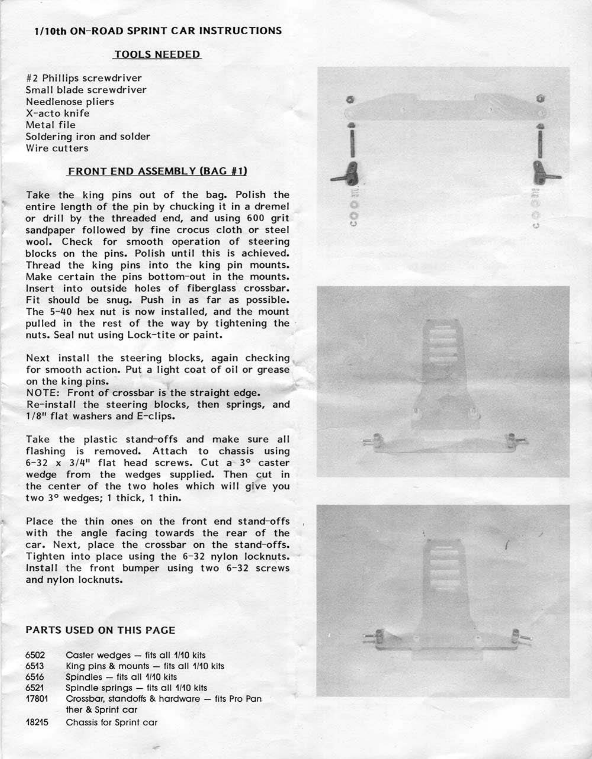
Refer
to
the
following
diagram
in
assembling
the
differential.
To
keep
your
Sprint
car's
performance
at
its
optimum,
keep
the
reci
procating
parts
clean
and
lightly
lubed
with
silicone
grease.
After
complete
assembly
of
the
differential,
insert
2
of
the
1/
4"
plastic
spacers
against
the
aluminum
diff.
hub,
and
insert
the
axle
through
the
rear
pod
.
Take
the
remaining
3
spacers
and
slide
them
on
the
axle
.
Now
install
the
othe
r
wheel
hub
.
Leave
a
very
slight
amount
of
side
play
in
the
axle
to
allow
for
free
r
otation.
NOTICE
The
rear
axle
is
made
of
carbon
fiber
which
is
a v
ery
st
r
ong,
light
mate
ri
al
.
However,
the
axle
will
wea
r
out
quickly
if
used
ve
ry
long
with
oilite
bushings
.
It
is
highly
re
comme
nded
that
the
oilite
by
replaced
with
1/4"
x
3/8"
ball
bearings.
(Parma
#7037)
Other
parts
suitable
for
use with Parma
1/
10
ON
R
OA
D CARS
3571
4020
4050
4052
4053
6000A
60008
6000C
60000
6000E
6000F
6000G
6000H
6000J
6000K
6018A
60188
6018C
60180
6018E
6018F
6018G
6044
6046
Front ball bearings
Wiper arm and button assembly
Silicone hook-up wire
16
ga. 2
ft
.
Silicone hook-up wire
16
ga.
10
ft.
13
ga
. hook-up wir e3
ft.
lengths
9T machined steel pinion
1
OT
machined steel pinion
11
T machined steel pinion
12T machined steel pinion
13T machined steel pinion
14T machined steel pinion
1ST
machined steel pinion
16T machined steel pinion
17T machined steel pinion
1ST
machined steel pinion
9T
aluminum pinion
10T aluminum pinion
11T aluminum pinion
12T aluminum pinion
13T aluminum pinion
14T aluminum pinion
1ST
aluminum pinion
44 tooth spur gear for Parma/Associated diH.
46
tooth spur gear for Parma/Associated
dill
.
IF
USING ASSJC.WHEEL
USEOUTER
HUB
SUP-
PUEO IN KIT.
~..:.--~1
TIGER
WHt::EL
HUB
I LOCK NUT
AXLE
6048
6062
6063
6064
7037
8038
8039
8055
11410
11500
11501
11515
11517
J
11!-lt:::-jH+-
l~l-~-
--
I
BALLS
EAR THRUST BEARING
ASSEMBLY
48tooth spur gear for Parma/Associated
diH
.
48
tooth Kimbrough spur gear
50
tooth Kimbrough spur ger
52
tooth Kimbrough spur gear
Rear ball bearings 1
/4"
x
3/8"
"Super Gripper" hood pins
Quick clip hood pins
Servo tape
1"
x
3".
super sticky
Shrink tube 1/16",
1/8",
and 1/4"
00
Heavy duty Tamiya connector sets
Pre-wired Tamiya connector sets
Resistor speed control without reverse
Resistor speed control with reverse