Parsec Technologies NEWFOUNDLAND User manual

NEWFOUNDLAND
Installation Instructions
e Newfoundland Emergency Hot spot is a large IP67 case with built-
in antennas that are optimized for the extra thick(3.5mm) plastic used
in industry strength cases. Both sets of LTE and Wi-Fi antennas were
designed for maximum performance even in remote areas where the
cellular infrastructure may have been compromised. Parsec has taken
the unique approach to design all the antennas to t safely into the lid of
the case reducing damage and loss of performance due to hard use. e
Newfoundland is congurable up to a 13 in 1 with up to 2 sets of 4X4
MIMO LTE, 4X4 MIMO WIFI and GPS/GNSS capable of running dual
SIM’s simultaneously. is 5G ready, 600 MHz – 6 GHz antenna is both
portable and IP67 rated.
REQUIRED TOOLS
REQUIRED ACCESSORIES
5/32 Hex Allen Screwdriver
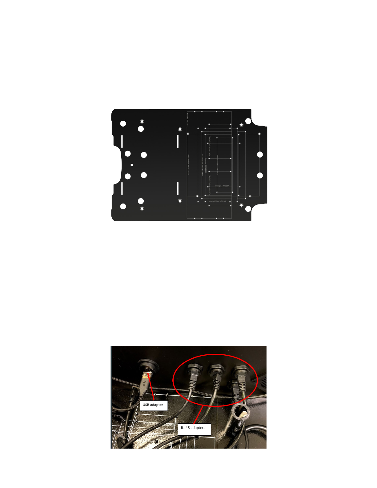
Router (select one of the following routers.)
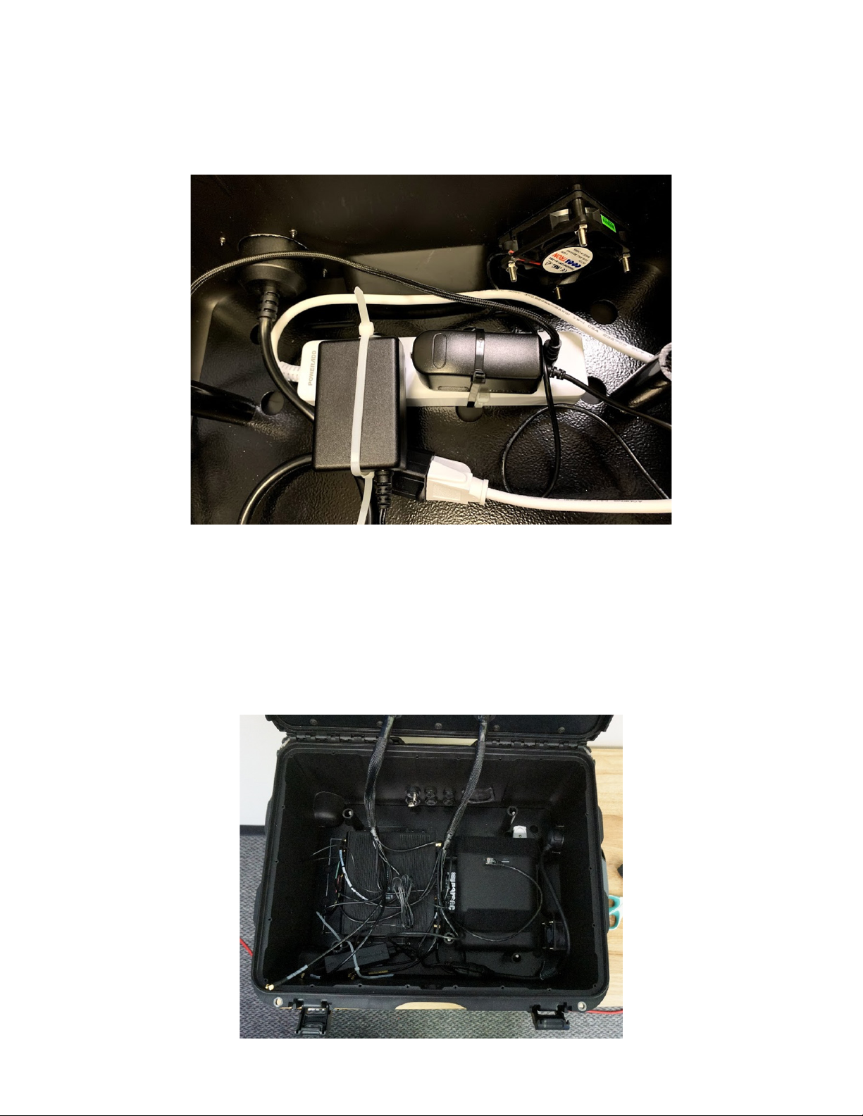
Battery: Chargetech 54k AC Battery Pack (OPTIONAL)
Ethernet Cords: 4pc (Length as required by the customer)
USB Cords - 1 pc (length as required by the customer)
Power Supply (required for router)
Battery Straps (OPTIONAL)
Extension Cord (NEMA 5-15 Plug to NEMA 5-15 Socket)
• CRADLEPOINT AER2200
• CRADLEPOINT IBR1700-1200M
• CRADLEPOINT E3000
• CRADLEPOINT IBR900-1200M (2)
• SIERRA WIRELESS AIRLINK MG90
• SIERRA WIRELESS AIRLINK MP70
• INSEEGO SKYUS 500
• INSEEGO SKYUS 300
Phillips Screwdriver
9” Zip Ties
Scissors

Router Installation:
Step 1.
Step 2.
Step 3.
Take off the top cover plate by unscrewing the 6 cap nuts using the 5/32 Hex Allen screwdriver. (Figure 1)
Check if the router needs brackets to mount it to the router mount plate. The Cradlepoint AER2200 and E3000 will need
brackets to mount. Use the brackets provided in the kit and assemble them onto the router. (Figure 2)
Zip Tie the surge protector to the router mount base plate. (Figure 3) Connect the AC plug of the surge protector to the
AC adapter on the case. (Figure 4)
FIGURE 1
FIGURE 2
FIGURE 3 FIGURE 4

Step 4.
Connect the Antenna cables to the router. Clean all connectors so there is no dust in the terminals. Follow the chart to
connect the cables. (Figures 5-7)
FIGURE 5
FIGURE 6
FIGURE 7

Step 5.
Step 6.
Step 1.
Step 2.
Choose the right AC power supply unit for the router and connect it to the router.
Choose four ethernet ports on the router that is going to be used the most. (LAN or WAN) Connect ethernet cords from
the four that are required and connect them to the ports on the case.
(It is recommended to choose at least 1 WAN and 2 LAN)(Figure 9)
Connect the USB adapter. The USB port can either be plugged into the surge protector for charging electronical
devices, or into the router for data transfer. (Figure 9)
Mount the router on the router mount base plate. Match the mount holes on the router to the holes on the router mount
base plate. Fasten the router to the plate using four 1/4-20, 1/4 screws provided in the kit. (Figure 8)
FIGURE 8
FIGURE 9
Router and Case Connection Instructions:

Battery Connection Instructions (OPTIONAL):
Step 3.
Step 1.
Step 2.
Connect the AC adapter of the fan and the router power supply unit to the surge protector. Zip tie the adapters to
secure them. Make sure the surge protector is switched on. (Figure 10)
Select a battery with an AC port for powering the router. We recommend the “Chargetech 54k AC Battery Pack”.
Strap the battery to the router mount base using velcro or zip ties. (Figure 11)
FIGURE 10
FIGURE 11

Step 3.
Step 4.
Turn off the AC switch and Battery power switch. Plug in the AC plug of the surge protector to the AC port of the battery.
(Figure 11)
Connect the charging port of the charger to the battery. Connect the AC plug from the charger to the AC adapter on
the case. (Figure 12)
FIGURE 11
FIGURE 12

Step 1.
Step 2.
Check all connections and make sure they are secure. Make sure all of the cables are connected to the right ports.
Before turning on the antenna, open the fan caps on the case. Be sure they are always open during operation. When
operating, keep the antenna away from any liquids or splashing. (Figure 13 & 14)
FIGURE 13
FIGURE 14
Antenna Operation:

Step 3.
Step 4.
Step 5.
Step 6.
Step 7.
Plug in one end of the Extension Cord (NEMA 5-15 Plug to NEMA 5-15 Socket) to the case (gure 13) and the other end to
the wall.
Turn on the power source. The router will turn on and display lights will start blinking. If you are using a battery, turn on
the main power switch and the AC switch of the battery.
Connect a network cable between the ethernet ports on a computer and one of the ethernet ports on the antenna
enclosure. Make sure you are connected to a LAN port and not a WAN port.
Bring up a web browser on the computer and type 192.168.0.1 into the address bar. You should see the Cradlepoint login.
(Figure 15)
Type the username and password. Username is “admin” by default. The password can be found on the information
cutout on the router. (Figure 16)
FIGURE 15
FIGURE 16

Step 8.
In the router, click on Status, Internet, and then Connections in the dropdown menu. You should see options related to
SIM cards installed. Select the option with a cellular SIM. (Figure 17)
FIGURE 17
FIGURE 18
parsec-t.com
CAUTION
To comply with FCC RF Exposure requirements in section 1.1310
of the FCC Rules, antennas used with this device must be installed
to provide a separation distance of at least 20 cm from all persons to
satisfy RF exposure compliance.
DO NOT
- Operate the transmitter when someone is within 24 inches of
the antenna.
- Install antenna or mast assembly on a windy day
- Install the mast close to power lines as it can cause serious injuries
or death.
WARNING
is document gives the detailed instructions to install an antenna to
the best of our knowledge. is document if for general information
only. It cannot be used as a warranty. Parsec Technologies, Inc. will
not accept any liability for any damage caused by an antenna due to
unknown variables.
Make sure the fan cap covers are open while using the antenna.
Install the sim in router before mounting on to the router mount plate.
Warnings:
Step 9.
If all of the steps are completed, the antenna should be on and operating. Close the top cover plate using the thread
forming screws provided in the kit. (Figure 18)
Table of contents