Partlow MRC 7700 User manual

Form 3029 • Price $32.00
Edition 4 • © April 1997
The Partlow Corporation • Two Campion Rd. • New Hartford, NY 13413 USA • 315-797-2222 • FAX 315-797-0403
MRC 7700
Installation, Wiring, Operation Manual
CIRCLE CHART RECORDER; RECORDER CONTROLLER; RECORDER CONTROLLER
PROFILER FOR MEASURING AND CONTROLLING RELATIVE HUMIDITY

PAGE 2
nformation in this installation, wiring, and operation
manual is subject to change without notice. One
manual is provided with each instrument at the time
of shipment. Extra copies are available at the price
published on the front cover.
Coyright © April 1997, The Partlow Corporation, all rights
reserved. No part of this publication may be
reproduced, transmitted, transcribed or stored in a
retrieval system, or translated into any language in any
form by any means without the written permission of the
Partlow Corporation.
This is the Fourth Edition of the MRC 7700 Recording Pro-
file Controller Manual. It was written and produced en-
tirely on a desk-top-publishing system. Disk versions are
available by written request to the Partlow Advertising and
Publications Department.
We are glad you decided to open this manual. It is written
so that you can take full advantage of the features of your
new MRC 7700 microbased chart recording profile
controller.
I
NOTE It is strongly recommended that Partlow equipped applications incorporate
a high or low limit protective device which will shut down the equipment
at a preset process condition in order to preclude possible damage to
property or products.
!
THE INTERNATIONAL HAZARD SYMBOL IS FOUNDADJACENT TO THE
PLATEN HOLD DOWN SCREW. IT IS IMPORTANT TO READ THIS
MANUAL BEFORE INSTALLING OR COMMISSIONING THE UNIT.
CAUTION: READ THIS MANUAL

PAGE 3
Table of Contents
SECTION 1 - GENERAL Page Number
1.1 Product Description 5
SECTION 2 - INSTALLATION & WIRING
2.1 Installation & Wiring 8
2.2 Unpacking 8
2.3 Location 8
2.4 Mounting 8
2.5 Preparation for Wiring 9
2.6 Wiring Connections 14
SECTION 3 - CONFIGURATION
3.1 Configuration (Set Up) 21
3.2 Configuration/Jumper Positioning 22
3.3 Operation Summary 22
3.4 Start Up Procedures 22
3.5 Front Panel Operation 23
SECTION 4 - OPERATION
4.1 Operation 43
4.2 Alarm Operation 47
4.3 Tune Mode Operation 48
SECTION 5 - SERVICE
5.1 Service 51
5.2 Changing Charts 51
5.3 Changing Pens 51
5.4 Calibration 52
5.5 Test Mode 57
5.6 Troubleshooting and Diagnostics (Error Code Definitions) 61
APPENDICES
A - Board Layouts and Jumper Positioning
A-1 Processor Board 69
A-2 SPST Relay/SSR Driver Output Board 70
A-3 SPDT Relay/SSR Driver Output Board 71
A-4 Current Output Board 72
B - Glossary 73
C - Order Matrix 76
D - Product Specifications 77
E - Software Reference Sheet 81
F - Profile Developement Sheet 85
Warranty Inside back cover

PAGE 4
FIGURES & TABLES
Figure 1-1 Recorder Description 5
Figure 1-2 Recorder Display 7
Figure 2-1 Installation Panel Dimensions Conduit 9
Opening Locations
Figure 2-2 Noise Suppression 11
Figure 2-3 Noise Suppression 11
Figure 2-4 Board and Terminal Locations 14
Figure 2-5 AC Power Input 15
Figure 2-6 Thermocouple Inputs 15
Figure 2-7 RTD Inputs 16
Figure 2-8 Milliamp and Volt Inputs 16
Figure 2-9 Remote Profile Run/Hold 17
Figure 2-10 Remote Setpoint Input VDC, mADC 17
Figure 2-11 Digital Communications 18
Figure 2-12 Relay Output 18
Figure 2-13 SSR Driver Output 19
Figure 2-14 Current Output 19
Figure 2-15 Transmitter Power Supply Input 20
Figure 2-16 Position Proportioning Control Output 20
Figure 3-1 Keypad Features 25
Figure 5-1 Changing Pens 50
Table 3-1 Program Mode Configuration Procedure 30
Table 3-2 Tune Mode Configuration Procedure 37
Table 3-3 Alarm Set Mode Calibration Procedure 39
Table 3-4 Profile Entry Mode Configuration Procedure 39
Table 3-5 Enable Mode Configuration Procedure 41
Table 4-1 Profile Continue Mode 44
Table 5-1 Calibration Procedures 53
Table 5-2 Test Procedures and Description 58
FLOW CHARTS
Flow - Calibration 52
Flow - Enable Mode 42
Flow - Program Mode 26
Flow - Test Mode 57
Flow - Tune Mode 36
Flow - Alarm Set 38

PAGE 5
Product Description 1.1
1.1.1 GENERAL
The instrument is a microprocessor based circular chart Recording Profile Controller capable
of measuring, displaying, recording and controlling Relative Humidity and/or Temperature
using Dry Bulb and Wet Bulb temperatures from a variety of inputs. Two process sensor input
terminal boards are provided on each instrument. To perform the Relative Humidity calcula-
tions both inputs must be the same type. (2- RTD, 2-J T/C, for best results a matched pair of
sensors should be used). The instruments can be specified as either a single or as a dual pen
model. The second pen can be selected as a profile control or a single setpoint control.
Recording, control functions, alarm settings, profile entry and other parameters are easily
entered via the keypad. All user data can be protected from unauthorized changes by the
Enable mode security system, and is protected against memory loss, as a result of AC power
outage, by battery back-up.
The process sensor input for each terminal board is user configurable to directly connect to
either thermocouple, RTD, VDC, or mADC inputs. Changes in input type can easily be made
by the user. Thermocouple and RTD linearization, as well as thermocouple cold junction
compensation, are performed automatically. The instrument process variable inputs are
isolated. An isolated 24 VDC regulated transmitter power supply can be provided in the
instrument for use with up to two 4 to 20 mADC process sensor transducers.
The instrument can be ordered to operate on either 115 VAC or 230 VAC power at 50/60 Hz.
The 230 VAC option includes a switch for selecting either 230 VAC or 115 VAC operation.The
Instrument is housed in a structural foam enclosure suitable for panel or surface mounting.
FIGURE 1-1
Pen 1 Display
Pen 2 Display
Pen 1 Reset Key
Pen 2 Reset Key
Scroll Key
Up Key
Down Key

PAGE 6
1.1.2 RECORDING
The instrument records the selected process variable on a 10-inch circular chart. One box of
standard charts is provided with each recorder. Charts are available in a wide selection of
ranges. Chart rotation speed is programmable from 0.1 to 999.9 hours per revolution in 0.1
hour increments. The instrument can be ordered with one or two pens. Pen 1 is red and Pen 2
is green. Pens are the disposable fiber-tip type.
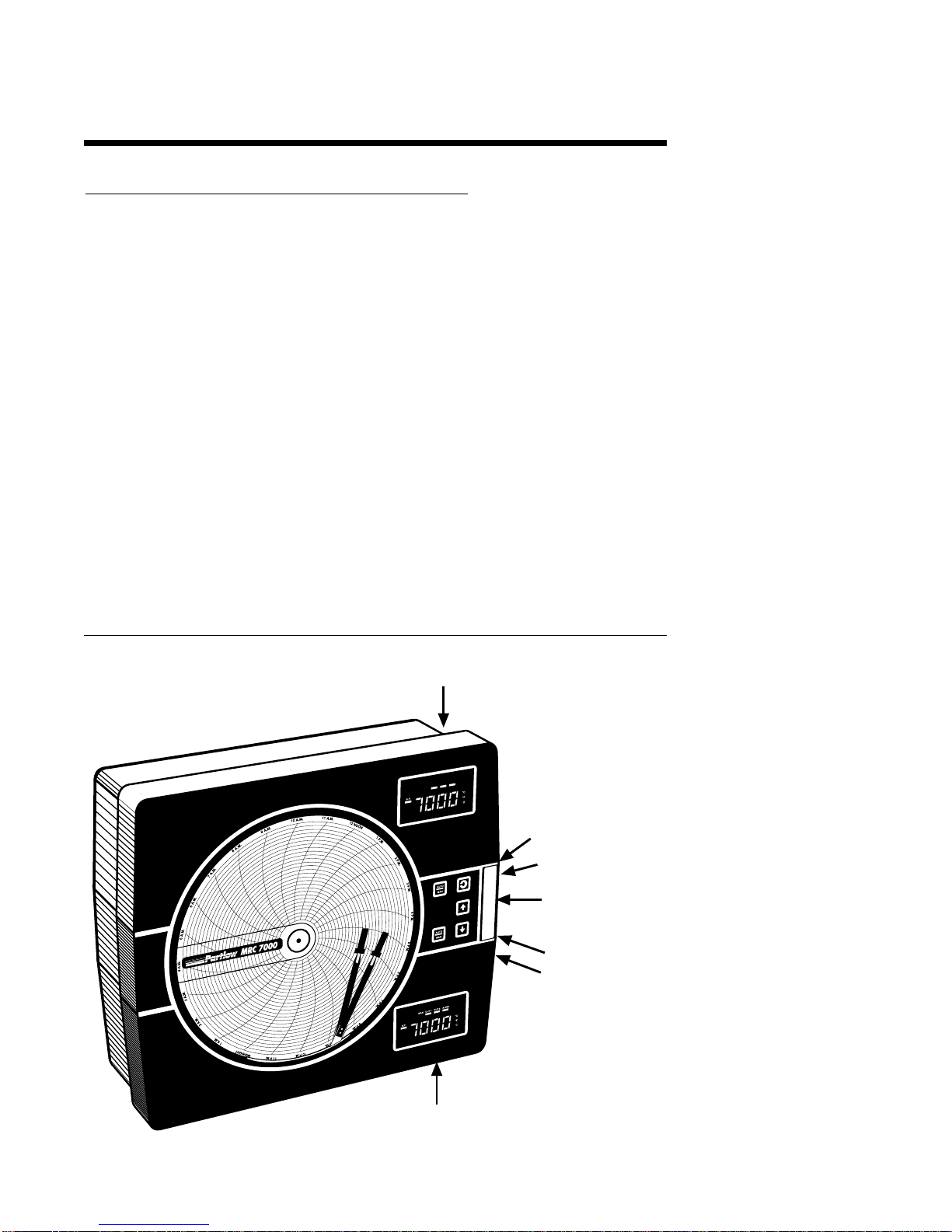
1.1.3 DISPLAYS
Each instrument is provided with a digital display and status indicator for each pen provided
(See Figure 1-1). The display may be configured to display the Dry Bulb Temperature, Wet
Bulb Temperature, or the Relative Humidity as the process value. During configuration the
display(s) is/are used to show the enabled modes of operation and the parameter codes.
The display in the upper right corner is for Pen 1, the display in the lower right corner is for
Pen 2 (if provided). The upper display provides status indication for the Manual mode
operation, Output 1, Output 2, Alarm , Setpoint, negative value, degrees C, degrees F, and
engineering units, Ramp, Soak and six Segment lamps. The lower display( if provided)
includes status indicators for Manual mode operation, Output 1, Output 2 , Alarm, Setpoint,
negative value, degrees C, degrees F, engineering units. (Relative Humidity will be indicated
in engineering units.) See Figure 1-2 (page 7).
Display resolution is programmable for 0.1 or 1 degree for thermocouple and RTD inputs, and
none, one, two or three decimal places for other input types. Relative Humidity will be
indicated as whole numbers only.
1.1.4 CONTROL
The instrument can be provided with relay, solid state relay driver and milliamp DC outputs.
Instruments can be programmed for on-off, time proportioning, current proportioning or
position proportioning control depending upon the output(s) present. Relay(s) and Solid State
Relay Driver(s) may be assigned to be on or off during the profile ramp and soak of a profile
segment. Switching between the Control mode and the Manual mode of operation is easily
accomplished with a dedicated key on the keypad. Switching is bumpless from the Control to
the Manual mode, and while in manual, adjustment of proportional outputs is possible. Each
pen of a dual pen recording controller is provided with its own AUTO/MANUAL key . Other
standard control features include proportional control output limits, setpoint limits, anti-reset
windup and a unique Automatic Transfer function. If configured, the Automatic Transfer
function allows manual control of the proportional output until the process reaches the setpoint
at which time the instrument will go into the Control mode of operation.
1.1.5 ALARM
An Alarm indicator is standard for each pen. Two alarm functions are provided for each pen
and the alarm indicator will light if either alarm for that pen is on. Alarm settings are program-
mable. Alarm type may be selected as process direct or reverse (high or low), deviation from
setpoint direct or reverse, and deviation band open or closed within the band. Alarm outputs
can be provided by assigning any relay(s) Single Pole/Single Throw (SPST) or Solid State
Relay (SSR) driver to the respective alarm.
1.1.6 PROCESS VALUE RE-TRANSMISSION OUTPUT
If an instrument is specified with mADC current output(s), any of the outputs may be pro-
grammed to operate as a process value re-transmission output. The output is scaleable but
can not be used as a control output while assigned as a process value re-transmission output.

PAGE 7
1.1.7 DIGITAL COMMUNICATIONS
The instrument can be ordered with a Digital Communications option that provides the
capability of bi-directional communications with a supervisory computer. A dual pen
instrument can have an individual address selected for each pen.
FIGURE 1-2
Digital Display
C
F
U
ALRM
Minus
Sign
OUT2OUT1MAN
SP
Setpoint
RAMP SOAK
SEG1 SEG2 SEG3 SEG4 SEG5 SEG6
Pen 1 Display
Digital Display
C
F
U
Alarm
ALRM
Minus
Sign
OUT2OUT1
MAN
SP
Manual Output 1 Output 2
Setpoint
Pen 2 Display (if Present)

PAGE 8
Installation and Wiring 2.1
Read these instructions carefully before proceeding with installation and operation. Electrical
code requirements and safety standards should be observed. Installation should be performed
by qualified personnel.
CAUTION: The Instrument AC power input is specified in the model number and on the wiring label
affixed to the the top center of the platen. Verify the AC power input required by the instrument prior
to proceeding with installation.
Unpacking 2.2
Remove the instrument from the carton and inspect for any damage due to shipment. If any
damage is noticed due to transit, report and file a claim with the carrier. Write the model
number and serial number of the instrument on the inside of the front cover of this Operation
Manual for future reference.
Location 2.3
Locate the instrument away from excessive moisture, oil, dust, and vibration. Do not subject
the instrument to operating temperatures outside of the 0 to 55°C (32 to 131°F) range.
Mounting 2.4
Figure 2-1 (page 9) shows an installation view and physical dimensions for a panel mounted
instrument.
The panel where the instrument will be mounted must provide rigid support for the approxi-
mately 20 pound instrument. Adjacent instruments may be mounted within a minimum of 2
inches horizontally and 3 inches vertically, providing that proper panel support is supplied.
PANEL MOUNTING HARDWARE REQUIRED: (not provided with instrument)
(4) 1/4"-20 x 2" flat head bolts w/nuts
(4) appropriate lock washers
PANEL MOUNTING:
1) Cut panel opening to the dimensions illustrated in Figure 2-1 (page 9).
2) Insert the instrument in the panel opening. Firmly fasten the instrument to the panel using
the nuts, bolts and lock washers.
SURFACE MOUNTING:
1) Install the mounting brackets, ordered separately, on the vertical sides of
instrument housing. Use the brackets to fasten the instrument to the surface.

PAGE 9
FIGURE 2-1
Preparations for Wiring 2.5
2.5.1 WIRING GUIDELINES
Electrical noise is a phenomenon typical of industrial environments. The following are guide-
lines that must be followed to minimize the effect of noise upon any instrumentation.
2.5.1.1 INSTALLATION CONSIDERATIONS
Listed below are some of the common sources of electrical noise in the industrial environ-
ment:
•Ignition Transformers
•Arc Welders
•Mechanical contact relay(s)
•Solenoids
Before using any instrument near the devices listed, the instructions below should be
followed:
1. If the instrument is to be mounted in the same panel as any of the listed devices,
separate them by the largest distance possible. For maximum electrical noise
reduction, the noise generating devices should be mounted in a separate
enclosure.
2. If possible, eliminate mechanical contact relay(s) and replace with solid state
relays. If a mechanical relay being powered by an instrument output device
cannot be replaced, a solid state relay can be interposed to isolate the
instrument.
3. A separate isolation transformer to feed only instrumentation should be
considered. The transformer can isolate the instrument from noise found on the
AC power input.
4. If the instrument is being installed on existing equipment, the wiring in the area
should be checked to insure that good wiring practices have been followed.
3
20.7 mm)
(190.5 mm)
(342.5 mm)
( 354 mm)
9
32 DIA.(7.1mm)
Panel cut-out for flush mounting
15 1
8(384.2 mm) 21
2(64 mm)
WIDTH OF COVER
416
91m
16
5
mm
)
EC1
12 5
871
2
13 1
2
1315
16
(65.9 mm)219
32
2.5"
63.5mm

PAGE 10
2.5.1.2 AC POWER WIRING
Earth Ground
The instrument includes noise suppression components that require an earth ground
connection to function. To verify that a good earth ground being is attached, make a
resistance check from the instrument chassis to the nearest metal water pipe or proven earth
ground. This reading should not exceed 100 ohms.
Neutral (For 115VAC)
It is good practice to assure that the AC neutral is at or near ground potential. To verify this, a
voltmeter check between neutral and ground should be done. On the AC range, the reading
should not be more than 50 millivolts. If it is greater than this amount, the secondary of this
AC transformer supplying the instrument should be checked by an electrician. A proper
neutral will help ensure maximum performance from the instrument.
2.5.1.3 WIRE ISOLATION/SEGRATION
The instrument is designed to promote proper separation of the wiring groups that connect to
the instrument. The AC power wire terminals are located near the top of the instrument
boards. The analog signal terminals are located near the bottom of the instrument boards.
Maintain this seperation of the wires to insure the best protection from electrical noise. If the
wires need to be run parallel with any other wiring type(s), maintain a minimum 6 inch space
between the wires. If wires must cross each other, do so at 90 degrees to minimize the
contact with each other and reduces cross talk. Cross talk is due to the EMF (Electro
Magnetic Flux) emitted by a wire as current passes through it.
2.5.1.4 USE OF SHIELDED CABLE
Shielded cable helps eliminate electrical noise being induced on the wires. All analog signals
should be run with shielded cable. Connection lead length should be kept as short as pos-
sible, keeping the wires protected by the shielding. The shield should be grounded at one end
only. The preferred grounding location is at the sensor, transmitter or transducer.
2.5.1.5 NOISE SUPPRESSION AT THE SOURCE
Usually, when good wiring practices are followed, no further noise protection is necessary.
Sometimes in severe electrical environments, the amount of noise is so great that it has to be
suppressed at the source. Many manufacturers of relays, contactors, etc., supply "surge
suppressors" which mount on the noise source.
For those devices that do not have surge suppressors supplied, RC (resistance-capacitance)
networks and/or MOV (metal oxide varistors) may be added.
Inductive Coils - MOV's are recommended for transient suppression in inductive coils con-
nected in parallel and as close as possible to the coil. See Figure 2-2. Additional protection
may be provided by adding an RC network across the MOV.
Contacts - Arcing may occur across contacts when the contact opens and closes. This results
in electrical noise as well as damage to the contacts. Connecting a RC network properly
sized can eliminate this arc.
For circuits up to 3 amps, a combination of a 47 ohms resistor and 0.1 microfarad capacitor
(1000 volts) is recommended. For circuits from 3 to 5 amps, connect 2 of these in parallel.
See Figure 2-3.

PAGE 11
FIGURE 2-2
FIGURE 2-3
Inductive
Load
0.5
mfd
1000V
220
ohms
115V 1/4W
230V 1W
Inductive
Load
RC
MOV
AC

PAGE 12
2.5.2 SENSOR PLACEMENT (Thermocouple or RTD)
If the temperature probe is to be subjected to corrosive or abrasive conditions, it should be
protected by the appropriate thermowell. The probe should be positioned to reflect true
process temperature:
In liquid media - the most agitated area.
In air - the best circulated area.
THERMOCUPLE LEAD RESISTANCE
Thermocouple lead length can affect instrument accuracy since the size (gauge) and the
length of the wire affect lead resistance.
To determine the temperature error resulting from the lead length resistance, use the following
equation:
Terr = TLe * L where; TLe = value from apropriate Table
L = length of leadwire in thousands of feet
TABLE 1
Temperature Error in °C per 1000 feet of leadwire
AWG Thermocouple Type
No.J K T R S E B N C
10 0.68 1.71 0.76 2.05 2.12 1.15 14.00 2.94 2.53
12 1.08 2.68 1.21 3.30 3.29 1.82 22.00 4.68 4.07
14 1.74 4.29 1.95 5.34 5.29 2.92 35.00 7.44 6.37
16 2.74 6.76 3.08 8.30 8.35 4.60 55.50 11.82 10.11
18 4.44 11.00 5.00 13.52 13.65 7.47 88.50 18.80 16.26
20 7.14 17.24 7.84 21.59 21.76 11.78 141.00 29.88 25.82
24 17.56 43.82 19.82 54.32 54.59 29.67 356.50 75.59 65.27
TABLE 2
Temperature Error in °F per 1000 feet of leadwire
AWG Thermocouple Type
No.J K T R S E B N C
10 1.22 3.07 1.37 3.68 3.81 2.07 25.20 5.30 4.55
12 1.94 4.82 2.18 5.93 5.93 3.27 39.60 8.42 7.32
14 3.13 7.73 3.51 9.61 9.53 5.25 63.00 13.38 11.47
16 4.93 12.18 5.54 14.93 15.04 8.28 99.90 21.28 18.20
18 7.99 19.80 9.00 24.34 24.56 13.44 159.30 33.85 29.27
20 12.85 31.02 14.12 38.86 39.18 21.21 253.80 53.79 46.68
24 31.61 78.88 35.67 97.77 98.26 53.40 641.70 136.07 117.49
Example
A recorder is to be located in a control room 660 feet away from the process. Usinging 16
AWG, type J themrocouple, how much error is induced?
Terr = TLe * L
TLe = 4.93 (°F/1000 ft) from Table 2
Terr = 4.93 (°F/1000 ft) * 660 ft
Terr = 3.3°F

PAGE 13
RTD LEAD RESISTANCE
RTD lead length can affect instrument accuracy. Size (gauge) and length of the wire used
affects lead length resistance.
To determine the temperature error resulting from the lead length resistance, use the following
equation:
Terr = TLe * L where; TLe = value from Table 3 if 3-wire or Table 4 if 2-wire
L = length of leadwire in thousands of feet
TABLE 3 3 Wire RTD
AWG No. Error °C Error °F
10 +/-0.04 +/-0.07
12 +/-0.07 +/-0.11
14 +/-0.10 +/-0.18
16 +/-0.16 +/-0.29
18 +/-0.26 +/-0.46
20 +/-0.41 +/-0.73
24 +/-0.65 +/-1.17
TABLE 4 2 Wire RTD
AWG No. Error °C Error °F
10 +/-5.32 +/-9.31
12 +/-9.31 +/-14.6
14 +/-13.3 +/-23.9
16 +/-21.3 +/-38.6
18 +/-34.6 +/-61.2
20 +/-54.5 +/-97.1
24 +/-86.5 +/-155.6
Example
An application uses 2000 feet of 18 AWG copper lead wire for a 3-wire RTD sensor. What is
the worst case error due to this leadwire length?
Terr = TLe * L
TLe = +/- .46 (°F/1000 ft) from Table 1
Terr = +/- .46 (°f/1000 ft) * 2000 feet
Terr = +/- 0.92 °F

PAGE 14
Wiring Connections 2.6
All wiring connections are typically made to the instrument at the time of installation. Connec-
tions are made at the terminal boards provided, two 12 gauge wires maximum, using copper
conductors only, except thermocouple inputs. Terminal blocks are designated TB1 through
TB13. See Figure 2-2 for the terminal block locations. The number of terminal blocks present
on the instrument depend upon the model number/hardware configuration.
FIGURE 2-4
2.6.1 ELECTRICAL CONDUIT OPENINGS
The instrument case will have 3 or 4 conduit openings, depending upon the number of outputs
specified. To help minimize electrical noise that may adversely affect the operation of the
instrument, the wires groups indicated below should be routed through the conduit opening
specified. See Figure 2-1 for conduit opening locations.
EC1- AC Power Input
EC2- Analog input and mADC outputs
EC3- SPST or SPDT relay or SSR driver outputs
EC4- SPST or SPDT relay or SSR driver outputs (provided when > 4 relays & SSR Drivers
total are specified)
Unused conduit openings should be sealed.
TB3 TB4 TB5
TB1
12
1 2 1 2 3 4 5 1 2 3 4 5
1 2 3 4 1 2 3 4 1 2 3 4
TB6 TB7 TB8
TB9
1 2 3 4
RELAY/SSR Driver
Board
TB10 TB11 TB12 TB13
1 2 1 2 1 2 1 2
Current Output Board
Processor Board
TB 2
1 2

PAGE 15
2.6.2 AC POWER WIRING CONNECTIONS
WARNING: Avoid electrical shock. AC power wiring must not be connected at the source distribution
panel until all wiring connections are completed.
FIGURE 2-5
AC Instrument Power Input
Connect the 115 VAC hot and neutral to terminals 1 and 2 respectively of TB1. See Figure 2-4
(page 14) for Terminal Block locations on the instrument. Connect the 230 VAC one leg to
each terminal, be sure to check the position of the Voltage Selector switch provided with 230
VAC instruments. The switch position must match the voltage input to the instrument.
FIGURE 2-6
Thermocouple Inputs
For Relative Humidity calculations both sensor inputs must be the same kind. For best results,
a matched pair of sensors should be used.
Use TB4 for the Dry Bulb input, and TB5 for the
Wet Bulb input. Connect the positive leg of the thermocouple to terminal 1, and the negative
to terminal 2. Be sure that the input conditioning jumpers are properly positioned for a
thermocouple input. See Appendix A-1 (page 68).
TB4 and TB5
12345
-
Grounded or
Ungrounded
Thermocouples
may be used
+
12
TB1
Connect the AC
ground at the
green ground screw
on the left side of
the inside of the
case
Line 1
~
Line 2
~

PAGE 16
FIGURE 2-7
RTD Inputs
For Relative Humidity calculations both sensor inputs must be the same kind. For best
results, a matched pair of sensors should be used.
Use TB4 for the Dry Bulb input, and TB5
for the Wet Bulb input. Connections are shown for 3 wire and 2 wire RTD inputs. If a three
wire device is used, install the common legs to terminals 2 and 3. If a two wire device is used,
install a jumper between terminals 2 and 3. Be sure that the input conditioning jumpers are
properly positioned for an RTD input. See Appendix A-1 (page 68).
FIGURE 2-8
Volt and milliamp Input
Make the volt and milliamp connections as shown below. Use TB4 for the Dry Bulb input, and
TB5 for the Wet Bulb input. Terminal 1 is positive and terminal 2 is negative. The milliamp
input requires the installation of an appropriate shunt resistor (ordered separately) between
terminals 1 and 2. Be sure that input conditioning jumpers are in the correct positions for the
input being connected. See Appendix A-1 (Page 68).
TB4 and TB5
12345
-
+TB4 and TB5
12345
-
+
Jumper
3 Wire RTD 2 Wire RTD
SUPPLIED BY
CUSTOMER
12345
+-
TB4 and TB5
SHIELDED
TWISTED
PAIR
SOURCE
+ - MAY BE
GROUNDED
OR
UNGROUNDED
NOTE: Fault detection
is not functional
for 0-5V or 0-20mA
inputs

PAGE 17
12345
+-
TB4 or TB5
SHIELDED
TWISTED
PAIR
SOURCE
+ -
12345
+-
TB4 or TB5
SHIELDED
MULTI-CONDUCTOR
CABLE
150 OHM
TO 10K OHM
POTENTIOMETER
FIGURE 2-9
Remote Profile Run/Hold
If the Remote Run/Hold option has been specified, make the connections as shown. The
Remote Run/Hold option provides the capability of halting and restarting a running profile
from the operation of a remote contact closure. The operation of the Remote Run/Hold is
determined by the Program mode parameter selected. The closure of a remote dry contact
will cause the profile to hold. Re-opening the contact will cause the profile to continue to run
from the point at which it was halted. If both pens on a dual pen instrument are selected to
profile control the Remote Run/Hold will affect the operation of both pens.
FIGURE 2-10
Remote Setpoint Input VDC, mADC (Optional for the second pen of dual pen instruments)
If Remote Setpoint option has been specified, make connections as shown. The remote
setpoint input may be selected as either 0 to 5 VDC or 1 to 5 VDC input in the Program mode
section. Make sure the configuration properly matches the input used. Connect the positive
lead to terminal 4, and the negative lead to terminal 3 (Terminal 3 is the ground, terminal 4 is
the input, terminal 5 is 5 VDC.) If a 4 to 20 mADC remote setpoint is to be used, the instru-
ment remote setpoint input should be configured for 1 to 5VDC in the Program mode, and a
250 ohm resistor should be installed across terminals 4 and 3.
SHIELDED
TWISTED
PAIR
12345
+-TB4
REMOTE
DRY
CONTACT

PAGE 18
FIGURE 2-11
Digital Communications Options
Connections are made as shown using TB2. Refer to the Protocol Manual, Form #2878 for
more details regarding the connections and how to use this option. This document is provided
only when this option has been specified. If the communications network continues on to other
instruments, connect the cable shields together, but not to the instrument. A terminating
resistor should be installed at the terminals of the last unit in the communications loop. If the
communications network ends at the instrument, the shield is not connected.
2.6.4 OUTPUT CONNECTIONS
Relay output(s), if provided in the instrument, may be assigned to control or alarm output
functions for Pen 1 and/or Pen 2 (if present). Current outputs may be assigned to control and
process value retransmission output for Pen 1 and/or Pen 2 (if present). The assignment of
the output function (s) are/is accomplished in the Program mode. SPST relay and/or SSR
driver output(s) is/are designated as Relay A through Relay H. SPST relays begin with Relay
A designation, then B, C, etc. SSR drivers begin with Relay H designation then G, F, etc.
except when 4 SSR drivers are required in conjunction with SPDT relays, then designation E
& F are not available. SSR driver designation becomes G, H, D, and C. SPDT relay output(s)
are designated as Relay A and Relay B only.
FIGURE 2-12A
SPST Relay Output
Connections are made to relays A through F as shown. Terminal connections are made using
TB6 (Relay/SSR Driver A, B), TB7 (Relay/SSR Driver C, D) and TB8 (Relay/SSR Driver E, F).
TOWARD THE
COMPUTER
TB2
12
NETWORK
CONTINUATION
(IF APPLICABLE)
Serial A Serial B
1234
LOAD
POWER
HOT
NEU
5 AMPERES
MAXIMUM
AT 115 VAC
N.O. C N.O. C
TB6 Relay A & B, Relay A Terminals 1 & 2
TB7 Relay C & D, Relay C Terminals 1 & 2
TB8 Relay E & F, Relay D Terminals 1 & 2

PAGE 19
FIGURE 2-12B
SPDT Relay Output
FIGURE 2-13
SSR Driver Output
Connections are made to relays H through A as shown. Terminal connections are made using
TB9, TB8, etc. depending on the number of SSR Driver outputs specified.
FIGURE 2-14
Current Output
Connections are made to current outputs A thruough D as shown. Each current output is
programmable as either 4 to 20 mADC or 0 to 20 mADC. Each output must be assigned to the
desired function in the Program mode. Terminal connections are made using TB10 through
TB13 for current output A through D respectively. Connect positive lead (+) to terminal 1 and
the negative lead (-) to terminal 2. Each current output will operate up to a 650 ohms
maximum load.
123
LOAD
POWER
HOT
NEU
5 AMPERES
MAXIMUM
AT 115 VAC
N.O. C N.C.
TB6 Relay A
TB7 Relay B
1234 SSR
+ -
TB6 THRU TB9
TB9 SSRD G, H - all cases
TB8 SSRD E, F - no SPDT relays
TB8 SSRD C,D - SPDT relay/s E and F not available
SHIELDED
TWISTED
PAIR
LOAD
+
-
650 OHMS
MAXIMUM
12
+-

PAGE 20
FIGURE 2-15
Transmitter Power Supply Input
If the isolated 24 VDC regulated transmitter power supply has been specified, the connec-
tions should be made as shown. Connections are made using TB3, terminal 1 is positive and
terminal 2 is negative. The power supply is capable of providing the power needed for up to
2 transducers.
FIGURE 2-16
Position Proportioning Control Output
Position Proportioning control requires that two relays (or SSR Drivers) and the Position
Proportioning Auxiliary input be specified. On a dual pen instrument either pen may be
configured with Position Proportioning control provided the outputs and auxiliary inputs have
been properly specified.
SHIELDED
TWISTED
PAIRS
12345
+-
TB4 or TB5
TB3
12
+
-
+
-
12345
+-TB4
TB3
12
+
-
12345
+-
TB
5
+
-
+
-
TWO WIRE
TRANSMITTERS TWO WIRE
TRANSMITTERS
Modulating Motor
L1
L2
OPEN
CLOSE C
3
4
5
TB4
or
TB5
1
2
3
4TB6, TB7
or TB8
Table of contents
Other Partlow Voice Recorder manuals