Paso PA212 User manual

1SERIE CMDSCMDS
CMDSCMDS
CMDS
PA212
CMDSCMDS
CMDSCMDS
CMDS
SISTEMA DI DIFFUSIONE SONORA COMPATTO
COMPACT MUSIC DISTRIBUTION SYSTEM
SYSTEME DE DIFFUSION AUDIO COMPACT
TABLE OF CONTENTS
1 General description
1.1 Introduction....................................4
1.2 Description ....................................4
1.3 Numbered references....................4
2 General warnings
2.1 General features ............................5
2.2 Power supply .................................5
2.3 Safety notes...................................5
3 Functions and connections
3.1 Microphone inputs .........................6
3.2 Microphone precedence................6
3.3 Auxiliary and CD input...................7
3.4 Loudspeakers output.....................7
3.4.1 Low impedance systems...............7
3.4.2 Constant voltage systems .............7
3.5 Connection to zones......................8
3.6 Equalizer socket ............................8
4 Operation
4.1 Starting up .....................................9
4.2 Using the cassette.........................9
player/recorder
4.3 Using the tuner .............................10
5 Technical specifications ............11
6 List of spare parts ......................12
SOMMARIO
1 Descrizione generale
1.1 Introduzione...................................4
1.2 Descrizione....................................4
1.3 Riferimenti numerati ......................4
2 Avvertenze generali
2.1 Raccomandazioni generali ............5
2.2 Alimentazione ................................5
2.3 Note di sicurezza ...........................5
3 Funzioni e connessioni
3.1 Ingressi microfonici ........................6
3.2 Precedenza microfonica................6
3.3 Ingresso ausiliario e CD ................7
3.4 Uscita altoparlanti ..........................7
3.4.1 Sistemi a bassa impedenza ..........7
3.4.2 Sistemi a tensione costante ..........7
3.5 Collegamento a zone ....................8
3.6 Presa equalizzatore.......................8
4 Uso dell’apparecchio
4.1 Messa in funzione .........................9
4.2 Uso del riproduttore / .....................9
registratore cassette
4.3 Uso del sintonizzatore ..................10
5 Caratteristiche tecniche.............11
6 Lista delle parti di ricambio.......12
SOMMAIRE
1 Description générale
1.1 Introduction...................................13
1.2 Description ...................................13
1.3 Références numerotées ...............13
2 Precautions générales
2.1 Criteres généraux .........................14
2.2 Alimentation..................................14
2.3 Conseils de sécurité .....................14
3 Fonctions et connexions
3.1 Entrées microphoniques ..............15
3.2 Précédence micro ........................15
3.3 Entrée auxiliaire et CD .................16
3.4 Sortie haut-parleurs......................16
3.4.1 Systèmes à basse impédance .....16
3.4.2 Systèmes à tension constante .....16
3.5 Branchement de plusieurs zones ....17
3.6 Prise équilibreur ...........................17
4 Utilisation de l’appareil
4.1 Mise en marche ............................18
4.2 Fonctionnement du lecteur/..........18
enregistreur de cassettes
4.3 Fonctionnement du tuner .............19
5 Caractéristiques techniques .....20
6 Liste des pièces détachées .......21
ISTRUZIONI PER L’USO INSTRUCTIONS FOR USE MANUEL D’ UTILISATION

2 SERIE CMDSCMDS
CMDSCMDS
CMDS
INHALTSVERZEICHNIS
1 Allgemeine Beschreibung
1.1 Einleitung......................................13
1.2 Beschreibung................................13
1.3 Referensnummern........................13
2 Allgemeine hinweise
2.1 Allgemeine Hinweise ....................14
2.2 Stromversorgung ..........................14
2.3 Sicherheitsanweisungen ..............14
3 Funktionen und anschlüsse
3.1 Mikrofoneingänge .........................15
3.2 Mikrofonvorrangschaltung ............15
3.3 Hilfseingänge und CD ..................16
3.4 Lautsprecherausgang...................16
3.4.1 Systeme mit niedriger Impedanz...16
3.4.2 Systeme mit konstanter Spannung ..16
3.5 Anschluß von Zonen ....................17
3.6 Entzerrerbuchse ...........................17
4 Gebrauch des geräts
4.1 Inbetriebnahme ............................18
4.2 Gebrauch des Kassettenabspiel-
Kassettenaufnahmegeräts ...........18
4.3 Gebrauch des abstimmgeräts ......19
5 Technische Eigenschaften ........20
6 Ersatzeilliste................................21
KORTE INHOUDSOPGAVE
1 Algemene beschrijving
1.1 Inleiding ........................................22
1.2 Beschrijving ..................................22
1.3 Nummerverwijzingen....................22
2 Algemene opmerkingen
2.1 Algemene criteria .........................23
2.2 Stroomvoorziening .......................23
2.3 Opmerkingen over de veiligheid ...23
3 Functies en verbindingen
3.1 Microfooningangen .......................24
3.2 Microfoonvoorrang........................24
3.3 Hulpingang en CD ........................25
3.4 Uitgang luidsprekers.....................25
3.4.1 Lage impedantiesystemen ...........25
3.4.2 Constante spanningssystemen ....25
3.5 Verbinding in zones ......................26
3.6 Compensatorcontactbus ..............26
4 Gebruik van het apparaat
4.1 Inwerkingstelling ...........................27
4.2 Gebruik bandjes reproductie/
opname-apparaat .........................27
4.3 Gebruik tuner................................28
5 Technische kenmerken ..............29
6 Lijst van onderdelen...................30
GEBRAUCHSANLEITUNG INSTRUCCIONES DE EMPLEO
PA212
KOMPAKTE BESCHALLUNGSANLAGE
COMPACT GELUIDSVERSPREIDERSYSTEEM
SISTEMA COMPACTO DE DIFUSIÓN SONORA
CMDSCMDS
CMDSCMDS
CMDS
GEBRUIKSAANWIJZING
INDICE
1 Descripción general
1.1 Introducción ..................................22
1.2 Descripción...................................22
1.3 Referencias numeradas ...............22
2 Advertencias generales
2.1 Criterios generales .......................23
2.2 Alimentación .................................23
2.3 Notas sobre la seguridad .............23
3 Funciones y conexiones
3.1 Entradas microfónicas..................24
3.2 Precedencia microfónica ..............24
3.3 Entrada para auxiliares y CD .......25
3.4 Salida altavoces ...........................25
3.4.1 Sistemas de baja impedancia ......25
3.4.2 Sistemas de tensión constante ....25
3.5 Conexión de zonas .......................26
3.6 Enchufe del ecualizador ...............26
4 Uso del aparato
4.1 Puesta en funcionamiento............27
4.2 Uso del reproductor /
grabador de cassettes..................27
4.3 Uso del sintonizador.....................28
5 Datos tecnicos ............................29
6 Partes de recambio ....................30

3SERIE CMDSCMDS
CMDSCMDS
CMDS
PA212
12 4 5 6 7 8 93
1312
1110
14 15 16 17 18 19 20
25242322
21
26

4 SERIE CMDSCMDS
CMDSCMDS
CMDS
1DESCRIZIONE GENERALE GENERAL DESCRIPTION
1.1 INTRODUZIONE
Nel ringraziarVi per aver scelto un prodotto PASO, vogliamo ricordarVi
che la nostra azienda opera con sistema di qualità certificato ISO 9002.
Tutti i nostri prodotti vengono pertanto controllati in ogni fase della
produzione per garantirVi la piena soddisfazione del Vostro acquisto.Per
ognievenienzalagaranziacoprirà,nell’annodivalidità, eventualidifettidi
fabbricazione. Vi raccomandiamo di leggere attentamente le seguenti
istruzioni d’uso per sfruttare appieno le prestazioni offerte da questo
prodotto e per evitare eventuali problemi.
1.3 RIFERIMENTI NUMERATI
[1] Riproduttore/registratore di compact cassette.
[2] Controllo del livello di uscita del riproduttore di compact cassette.
[3] Sintonizzatore digitale AM/FM.
[4] Controlli di tono.
[5] Display del sintonizzatore.
[6] Controllo di volume generale.
[7] Controllo del livello di uscita del sintonizzatore.
[8] Indicatore di accensione e del livello di uscita.
[9] Selettori delle zone.
[10] Controlli di livello degli ingressi AUX e CD.
[11] Presa jack per ingresso microfonico 1.
[12] Controlli di livello degli ingressi microfonici.
[13] Interruttore di rete.
[14] Spina di rete con fusibile incorporato.
[15] Selettore della tensione di rete.
[16] Interruttore della alimentazione esterna in c.c.
[17] Presa per filo d’antenna (banda FM).
[18] Morsettiera per precedenza microfonica.
[19] Morsettiera uscite altoparlanti.
[20] Antenna per la banda MW.
[21] Morsettiera per alimentazione esterna in c.c.
[22] Prese XLR per ingressi microfonici.
[23] Prese phono PRE OUT/PWR IN con cavallotto.
[24] Prese phono per ingressi AUX e CD.
[25] Connessione di massa telaio.
[26] Filo d’antenna per banda FM.
1.2 DESCRIZIONE
Questo apparecchio costituisce un completo sistema sonoro in grado di
sonorizzare ambienti di piccole e medie dimensioni in modo
completamenteautonomo.Leprincipalicaratteristichetecniche efunzionali
possono essere così riassunte:
• Riproduttore/registratoreautoreversedi compact cassetteconcomandi
servoassistiti.
• Sintonizzatore AM/FM digitale con 28 memorie.
• Due ingressi ausiliari.
• N°4 ingressi bilanciati per microfoni di tipo dinamico.
• Funzione di precedenza automatica di un ingresso microfonico sugli
ingressi ausiliari, sul riproduttore di compact cassette e sul
sintonizzatore.
• N°1 ingresso/uscita per collegamento ad elaboratori sonori quali
equalizzatori, processori antilarsen o ad un amplificatore di potenza
esterno.
• Regolazione di tono.
• Generatore di segnale di preavviso a 4 toni, regolabile.
•POSSIBILITÀ DI SELEZIONARE TRE DIFFERENTI GRUPPI D’ALTOPARLANTI (ZONE).
1.1 INTRODUCTION
While thanking you for having chosen a PASO product, we would like to
remindyouthatourcompanyworksaccordingtoa QualitySystemcertified
forcompliance with ISO 9002 standards.Thismeans that all our products
are checked during every phase of manufacturing in order to guarantee
that you will be fully satisfied with your purchase. At all events, the
guarantee will cover any manufacturing flaws for the whole year for which
it is valid.We recommend that you read the following instructions for use
carefully in order to exploit in full the performance of this product and to
avoid any problems.
1.2 DESCRIPTION
This equipment consists of a complete sound system capable of
broadcasting sound in small and medium-sized environments in a fully
independent manner. Its main technical and functional features can be
summarised as follows:
• Autoreverse compact-cassette player/recorder with servoed controls.
• Digital AM/FM tuner with 28 storage cells.
• Two auxiliary inputs.
• 4 balanced inputs for dynamic microphones.
• Automatic priority function for one microphone input over the auxiliary
inputs, the compact-cassette player and the tuner.
• 1 input/output for connection to sound processing equipment such as
equalizers or anti-Larsen processor, or to an external power amplifier.
• Tone adjustment.
• Four-tone adjustable warning signal.
•POSSIBILITY OF SELECTING THREE DIFFERENT GROUPS (ZONES) OF LOUDSPEAKERS.
1.3 NUMBERED REFERENCES
[1] Compact-cassette player/recorder.
[2] Output level control for the compact-cassette player.
[3] Digital AM/FM tuner.
[4] Tone controls.
[5] Tuner display.
[6] General volume control.
[7] Tuner output level control.
[8] Power and output level indicator.
[9] Zone selector switches.
[10] AUX and CD input level controls.
[11] Jack type socket for microphone 1 input.
[12] Microphone input level controls.
[13] Mains switch.
[14] Mains plug with built-in fuse.
[15] Mains voltage selector switch.
[16] External DC power supply switch.
[17] Socket for antenna cable (FM band).
[18] Terminal strip for microphone precedence.
[19] Loudspeakers output terminal strip.
[20] Aerial for MW band.
[21] Terminal strip for external DC power supply.
[22] XLR sockets for microphone inputs.
[23] PRE OUT/PWR IN phono sockets with jumper.
[24] Phono socket for AUX and CD inputs.
[25] Frame ground connection.
[26] Antenna cable for FM band.

5SERIE CMDSCMDS
CMDSCMDS
CMDS
GENERALWARNINGS2AVVERTENZE GENERALI
2.1 RACCOMANDAZIONI GENERALI
Per un corretto funzionamento dell’apparecchio è opportuno osservare
alcuni criteri di massima nell’esecuzione dei collegamenti:
• evitare il posizionamento di cavi e di microfoni sul mobile
dell’apparecchio.
• evitare di stendere le linee di segnale parallele a quelle di rete;
osservare una distanza minima di 30/40 cm.
• posizionare le linee di ingresso e le linee di uscita distanti tra loro.
• posizionare i microfoni al di fuori dell’angolo di radiazione dei diffusori
sonori per evitare il fenomeno di reazione acustica (effetto Larsen).
2.3 NOTE DI SICUREZZA
Ogniinterventoall’interno dell’apparecchio, quale laselezionedi alcuni
modi d’uso o la sostituzione di fusibili, deve essere effettuato solo da
personale specializzato:la rimozione del coperchio rende accessibili
parti con rischio di scosse elettriche.
Prima di rimuovere il coperchio accertarsi sempre che il cavo di rete
siastaccato.Nel casodiaccidentalecadutadi liquidi sull’apparecchio,
staccare immediatamente la spina di rete ed interpellare il centro di
assistenza PASO più vicino. La connessione di massa telaio [25]
consente di collegare altre apparecchiature per la sola funzione di
schermatura deisegnaliabassolivello:questa presa non deve essere
utilizzata per il collegamento di sicurezza del telaio alla terra.
2.2 ALIMENTAZIONE
Questo apparecchio è predisposto per il funzionamento con tensione
di rete a 230 V ± 10% 50/60 Hz. È possibile utilizzare l’apparecchio
anche con una tensione di rete di 117 V ± 10% 50/60 Hz;a tal scopo è
necessario portare il selettore [15] (coperto da uno sportellino di
sicurezza) in posizione “115V” e sostituire il fusibile di rete, alloggiato
nell’apposito vano della spina di rete [14], con uno adeguato alla
tensione di alimentazione di 117 V il cui valore è riportato a lato del
portafusibile; in fig. 2.2.1 è illustrato come accedere al fusibile per la
sua sostituzione. Il sistema compatto PA212 può anche essere
alimentato con una sorgente esterna di corrente continua con tensione
di 24 V che deve essere applicata, rispettando le polarità, ai relativi
terminali della morsettiera [21].L’interruttore “DC SW” [16] interrompe il
collegamento alla sorgente esterna di alimentazione.In accordo con le
normative di sicurezza, l’interruttore di accensione [13]agisce solo sulla
tensione di rete. In dotazione all’apparecchio é fornito un cavo di
alimentazione con filo di terra; il terminale di terra della spina di rete
non deve essere rimosso in alcun caso.Collegare la spina di rete [14]
dell’apparecchio alla rete elettrica utilizzando l’apposito cavo fornito in
dotazione;assicurarsichelapresadicorrente sia dotata di collegamento
di terra a norma di legge. Il circuito di alimentazione del sistema
compatto PA212 è protetto da un fusibile posto all’interno
dell’apparecchio nella posizione evidenziata in fig.2.2.2.
Fig. 2.2.1
2.3 SAFETY NOTES
Any activities inside the apparatus, such as selecting some of the
operating modes, the installation of accessories or the replacement
of fuses, must be carried out by specialized personnel only: when the
cover is removed, parts liable to cause electric shocks are exposed.
Beforeremoving the cover,always makesurethat the powercordhas
been disconnected.
In the event that liquid is accidentally spilt onto the apparatus,
disconnectthemainsplugimmediately and contact thenearestPASO
Service Centre. The chassis earth connection [25] may be used to
connect other equipment only for the purpose of shielding the low
signals: this socket may not be used to connect the chassis to earth
forsafetypurposes.
2.1 GENERAL FEATURES
For proper unit operation, use the following instructions when making the
connections:
• Do not place cables or microphones on the unit cabinet.
• Donotlaysignallinesparallelto powerlines.Ensure aminimumdistance
of 30/40 cm between them.
• Keep input lines and the output lines far apart.
• Keep the microphones outside the operating span of the speakers to
avoid acoustic feedback (Larsen effect).
2.2 POWER SUPPLY
The unit is supplied for 230 V ± 10% 50/60 Hz supply voltage. It's
possible to use the equipment even with a 117 V ± 10%
50/60 Hz main voltage; for this reason it is necessary to put the
selector [15] - covered by a safety door - on “115 V” position and
replace the mains fuse, that is located in the mains plug proper
space [14] , with one suitable to the main voltage, whose value is
marked beside the fuse.Figure 2.2.1 shows how to replace the fuse.
PA212 compact system may also supplied by a constant voltage
external source, 24 V tension, that must be applied to the terminal
board [21], according to their polarity.The “DC SW” switch [16] cuts
the connection to the external supply source.According to the safety
regulations, the power on switch [13] acts only on the main tension.
The device is issued with a ground wire; the plug ground tap mustn't
be removed. Connect the equipment mains plug [14] to the mains
through the issued wire; make sure that the socket is issued,
according to law, with ground connection. PA212 compact system
circuit is protected by a fuse that is located inside the equipment as
shown in Figure 2.2.2.
Fig. 2.2.2

6 SERIE CMDSCMDS
CMDSCMDS
CMDS
3FUNZIONI E CONNESSIONI
3.1 INGRESSI MICROFONICI
AllepreseXLR“MIC.1÷4” [22] è possibile collegare tutti imicrofoni PASO
di tipo dinamico, i collegamenti a queste prese sono riportati in fig.3.1.1.
L’ingresso microfonico N°1 è disponibile anche sul frontale
dell’apparecchio con una presa jack Ø 6,3 mm [11]; la connessione a
questa presa, riportata in fig.3.1.2, è di tipo sbilanciato.Non è ammesso
l’usocontemporaneodelledue prese dell’ingresso microfonicoN°1.Ogni
ingresso microfonico dispone di un proprio controllo di livello [12] per
dosare opportunamente l’ampiezza dei vari segnali. L’ingresso
microfonico N°1 dispone, inoltre, della funzione di precedenza
automatica:parlando al microfono collegato a questo ingresso verranno
automaticamente ammutoliti gli ingressi ausiliari (AUX e CD), il
riproduttore di nastri e il sintonizzatore;il livello della soglia di attivazione
del circuito di precedenza automatica è dipendente dalla posizione della
manopola “MIC.1” [12].
Fig. 3.1.1 Fig. 3.1.2
3.2 PRECEDENZA MICROFONICA
Chiudendo i contatti della morsettiera “PRECEDENCE” [18] vengono
ammutoliti gli ingressi ausiliari, il riproduttore di nastri e il sintonizzatore;
inoltre, viene generato un segnale di preavviso a quattro toni (440 Hz,
554 Hz, 659 Hz e 880 Hz). È possibile modificare il livello di uscita e la
velocità di esecuzione del segnale di preavviso agendo rispettivamente
sui trimmer VR5 e VR3 posti all’interno dell’apparecchio; in fig.3.2.1 è
illustrata la posizione dei trimmer.
Fig. 3.2.2
NOTA:
si raccomanda di non modificare la regolazione dei vari trimmer, al di
fuori di VR5 e VR3, in quanto la loro taratura può essere effettuata
soltanto in un centro di assistenza PASO.
Per sfruttare efficacemente la funzione di precedenza è possibile
utilizzareilmicrofonoPASOmod.M906olabasemod.B501, collegando
l’uscita audio di questi ad uno degli ingressi microfonici e i terminali di
alimentazione/precedenzaall’appositamorsettieradell’apparecchiocome
mostrato in figura 3.2.2.
1: schermo / shield
2: segnale (lato caldo) / signal (hot side)
3: segnale (lato freddo) / signal (cold side)
3.1 MICROPHONE INPUTS
Any PASO microphone of the dynamic type may be connected to the
“MIC.1 to 4” XLR sockets [22]. The connections to these sockets are
shown in Figure 3.1.1. Microphone n° 1 input is also available on the
front panel of the equipment, by means of a 6.3 mm diameter jack [11].
Connection to this socket, shown in Figure 3.1.2, is of the unbalanced
type.Simultaneous use of the two microphone n° 1 input sockets is not
permitted. Each microphone input has its own level control [12] for
adjustingtheamplitudeofthevarioussignalsasappropriate.In addition,
microphone n° 1 input has the automatic priority function. When the
microphone connected to this input is being used to speak with, the
auxiliary inputs (AUX and CD) will be automatically muted as well as
the tape player and the tuner.The threshold level for activation of the
automatic priority circuit depends on the position of the “MIC.1”
knob [12].
3.2 MICROPHONE PRECEDENCE
On closing the contacts on the “PRECEDENCE”terminal strip [18], the
auxiliary inputs, the tape player and tuner are muted. In addition,
a four-tone (440 Hz, 554 Hz, 659 Hz and 880 Hz) warning signal is
generated.It is possible to adjust the output level and the speed at which
the signal is sounded by means of trimmers VR5 and VR3 respectively:
the trimmers are located inside the apparatus; their positions are
illustrated in Fig.3.2.1.
FUNCTIONS AND CONNECTIONS
1: schermo e ritorno segnale /
shield and return of signal
2: ingresso segnale /
signal input
Fig. 3.2.1
NOTE:
We strongly advice not to adjust the various trimmers in any way,
apart fromVR5 andVR3,since they can only be gauged by a PASO
technical assistance centre.
In order to exploit the precedence function effectively, it is possible to
use the PASO mod. M906 microphone or the mod. B501 base,
connecting the audio output of these to one of the microphone inputs
and the power supply/precedence terminals to the appropriate terminal
strip on the apparatus, as shown in Figure 3.2.2.

7SERIE CMDSCMDS
CMDSCMDS
CMDS
3FUNZIONI E CONNESSIONI
3.3 INGRESSO AUSILIARIO E CD
Allepresephono“AUX” e “CD”[24] è possibile collegare,rispettivamente,
unasorgentemusicaleadalto livello(registratorea nastro,radioricevitore
permicrofonisenza filo,ecc.)e un riproduttoredicompactdisc. Icontrolli
di livello [10] permettono di dosare opportunamente l’ampiezza dei
segnali relativi a questi due ingressi.
3.4 USCITA ALTOPARLANTI
Le uscite di potenza per i diffusori sono disponibili sulla morsettiera
[19].È possibile realizzare un impianto di diffusione sonora utilizzando
sia diffusori a bassa impedenza, sia diffusori dotati di traslatore di linea.
In entrambi i casi il carico complessivo non deve essere tale da
sovraccaricare l’amplificatore: si raccomanda, cioè, di non applicare
diffusori o gruppididiffusori conimpedenzapiùbassadiquellanominale
della presa alla quale sono collegati. Non è consigliabile realizzare
impianti di diffusione misti (a bassa impedenza e a tensione costante).
3.3 CD AND AUXILIARY INPUT
A high-level source of music (tape recorder, radio-receiver for wireless
microphones, etc.) and a compact disk player can be connected
respectively to the “AUX” and “CD” sockets [24]. Thanks to the level
controls [10], it is possible to adjust the amplitude of the signals for
these two inputs in the appropriate manner.
3.4 LOUDSPEAKERS OUTPUT
The power outputs for the loudspeakers are available on the terminal
strip [19]. It is possible to set up a sound-broadcasting system using
either low-impedance loudspeakers or loudspeakers equipped with a
line transformer. In either case, the overall load must not be such as to
overload the amplifier. It is therefore advisable not to connect
loudspeakers or groups of loudspeakers with lower impedance values
than the rated impedance of the socket to which they are connected. It
is not advisable to set up mixed broadcasting systems (using both low-
impedance and constant-voltage equipment).
3.4.1 LOW IMPEDANCE SYSTEMS
For applications requiring use of a small number of loudspeakers, the
line linking them can be connected between the common terminal “0”
and one of the three 4, 8or 16 ohm sockets of the terminal strip [19].
The connection of the loudspeakers, of the series or parallel or mixed
type, must supply an impedance calculated to be equal to one of the
three sockets. Figure 3.4.1 shows an example of a connection with two
8 ohm loudspeakers connected in parallel.
3.4.2 CONSTANT VOLTAGE SYSTEMS
In the case of systems with a large number of loudspeakers and/or in
which the distances between the amplifiers and the loudspeakers is
very large, it is preferable to use a constant voltage distribution system
(also known as a high-impedance system). In this type of system, the
loudspeakers, which are equipped with transformers for adapting the
impedance, are all shunted to the line (see the example in Figure 3.4.2).
Because of this, the system is easy to set up, and if one of the
loudspeakers should become disconnected from the line for any reason,
the rest of the system would continue to work normally. The constant
voltages available as outputs from the amplifier are 70 and 100 V, with
rated impedance values of 41 and 84 ohm respectively.
FUNCTIONS AND CONNECTIONS
Fig. 3.4.1 Fig. 3.4.2
3.4.1 SISTEMI A BASSA IMPEDENZA
In applicazioni che richiedono l’uso di pochi altoparlanti, la linea di
collegamento può essere connessa tra il terminale comune “0” ed una
delle tre prese 4, 8o 16 ohm della morsettiera [19]. Il collegamento
degli altoparlanti, di tipo serie o parallelo o misto, deve fornire
un’impedenza calcolata pari ad una delle tre prese. In figura 3.4.1 é
riportato un esempio di collegamento con due altoparlanti da 8 ohm
ciascuno connessi in parallelo.
3.4.2 SISTEMI ATENSIONE COSTANTE
Nel caso di impianti con un gran numero di diffusori e/o con distanze tra
amplificatori ed altoparlanti molto elevate é preferibile utilizzare un
sistema di distribuzione a tensione costante (definito anche ad alta
impedenza).In questo tipo diimpianto,i diffusori, provvistiditrasformatori
di adattamento di impedenza, sono tutti collegati in derivazione alla
linea (vedi es. di Fig. 3.4.2); questo particolare rende di facile
realizzazione l’impianto e, nel caso in cui un altoparlante dovesse per
qualche motivo scollegarsi dalla linea, il resto dell’impianto
proseguirebbe nel suo regolare funzionamento. Le tensioni costanti
disponibiliinuscitadall’amplificatoresonoda70e100V, con impedenza
nominale, rispettivamente, di 41 e 84 ohm.

8 SERIE CMDSCMDS
CMDSCMDS
CMDS
3.6 EQUALIZER SOCKET
It is possible to connect external equipment for processing the amplified
signals, such as equalizers or anti-Larsen processors, to the“PRE OUT”
and“PWR IN”sockets[23].To use thesesockets it isnecessary to remove
the metal jumper inserted into them. It is also possible to connect an
additional power amplifier to the “PRE OUT” socket in order to extend
the sound-broadcasting capacity of the system, if required.
Fig. 3.5.1
3FUNZIONI E CONNESSIONI FUNCTIONS AND CONNECTIONS
3.5 COLLEGAMENTO A ZONE
Il sistema compatto PA212 dispone della possibilità di selezionare tre
differenti zone di diffusione tramite gli interruttori “ZONE SELECTOR”
[9]. Gli interruttori interrompono il collegamento al terminale comune
dell’uscita di potenza dell’apparecchio.Per la realizzazione di impianti a
più zone di diffusione si consiglia di utilizzare esclusivamente le uscite
a tensione costante 70 e 100 V. In fig. 3.5.1 è riportato un esempio di
collegamento a tre zone più una quarta zona non escludibile.
3.5 ZONE CONNECTION
With the PA212 compact system, it is possible to select three different
broadcasting zones, thanks to the “ZONE SELECTOR” switches [9].
These switches cut off the connection to the common terminal of the
poweroutputofthesystem.Whensetting up systems comprisingseveral
broadcasting zones, it is advisable to use only the70 and 100V constant
voltage outputs. Figure 3.5.1 shows an example of a connection with
three zones plus a fourth zone that cannot be excluded.
3.6 PRESA EQUALIZZATORE
Alle prese “PRE OUT” e “PWR IN” [23] è possibile collegare
apparecchiature esterne per l’elaborazione del segnale amplificato quali
equalizzatori o processori antilarsen. Per utilizzare queste prese è
necessario rimuovere il cavallotto metallico in esse inserito.Alla presa
“PRE OUT” è anche possibile collegare un amplificatore supplementare
di potenza per estendere, eventualmente, le capacità di sonorizzazione
dell’impianto.

9SERIE CMDSCMDS
CMDSCMDS
CMDS
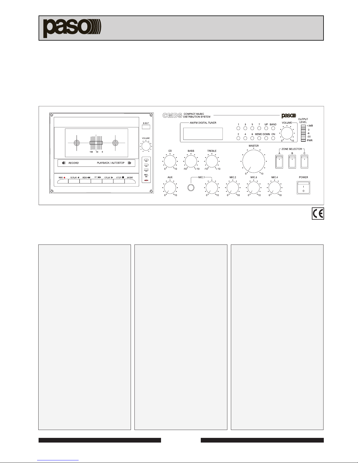
4.1 MESSA IN FUNZIONE
Alimentare l’apparecchio secondo le modalità riportate al par. 2.2 e
accenderel’apparecchio;la spia“PWR”, integratanell’indicatoredilivello
[8], si illuminerà. Selezionare, se utilizzate, le zone di ascolto tramite gli
appositiinterruttori [9].Dosare opportunamente i vari controllidilivello[2,
7,10 e12] delle sorgenti sonore utilizzate e correggere,senecessario, la
timbrica agendo sui controlli di tono “BASS” e “TREBLE” [3] o
sull’equalizzatore esterno (se disponibile).Nei paragrafi successivi sono
riportate le istruzioni dettagliate del riproduttore/registratore a cassette
[1] e del sintonizzatore [3].
4.2 USO DEL RIPRODUTTORE/REGISTRATORE
A CASSETTE
Aprire il vano cassetta premendo il tasto “EJECT” ed introdurre una
compact-cassetta; selezionare la modalità di riproduzione agendo sul
tasto “MODE”:
NORMALE
(riproduzione di un singolo lato)
AUTOMATICA - SINGOLO CICLO
(riproduzione singola di entrambi i lati del nastro)
AUTOMATICA - CICLO CONTINUO
(riproduzione continua di entrambi i lati del nastro)
laselezioneeffettuatasarà indicatadall’accensionedelled corrispondente.
Avviarela riproduzionedelnastropremendo il tasto“F.PLAY”o “R.PLAY”;
perinterromperelariproduzioneagiresultasto“STOP”.Iduetasti“REW.”
e“F.F.”consentonorispettivamenteil riavvolgimentool’avanzamentoveloce
del nastro.
Per registrare il programma sonoro in uscita, derivato dalla miscelazione
dei vari ingressi, inserire nell’apposito vano una cassetta vergine,
l’apparecchio riconoscerà automaticamente il tipo di nastro; selezionare
la modalità di registrazione, normale o due lati automaticamente (al
termine del primo lato la registrazione proseguirà sul secondo lato),
utilizzando il tasto “MODE”.
NOTA: indipendentemente dalla modalità selezionata, la funzione
ciclocontinuo
non è in questo caso abilitata e la registrazione cesserà
una volta terminati entrambi i lati della cassetta).
Premendoiltasto“REC.”il registratoresipredispone incondizioned’attesa
(pausa) e il led “REC.” lampeggerà; avviare quindi la registrazione
premendo il tasto relativo al senso di scorrimento del nastro desiderato:
“F.PLAY”o“R.PLAY”.Il livellodi registrazioneèregolato automaticamente,
in ogni caso è buona norma effettuare sempre delle prove preliminari
prima di procedere alla registrazione di un nastro.
Sono di seguito elencati alcuni consigli riguardanti l’uso delle compact-
cassette e la manutenzione del riproduttore:
- utilizzare cassette di buona qualità.
- sostituire le cassette troppo usurate o danneggiate.
- evitarel’uso di cassette di durata eccessiva(adesempioquelleda 120
minuti).
- provvedere periodicamente alla pulizia dei rullini pressori in gomma,
degli alberini di trascinamento e della testina della meccanica di
riproduzione.Per questa operazioneè consigliabile utilizzareleapposite
cassette normalmente reperibili in commercio nei negozi specializzati.
Evitare l’uso di prodotti come alcool denaturato e cotone.
4USO DELL’APPARECCHIO
4.1 STARTING UP
Power up the equipment following the procedure illustrated in paragraph
2.2 and switch it on.The “PWR” lamp built into the level indicator [8] will
light up. Select the listening zones, if used, by means of the switches
provided for this purpose [9]. Adjust the various level controls [2, 7, 10
and 12] of the sound sources used as appropriate, and if required, adjust
the tone-colour by setting the “BASS” and “TREBLE” controls [3] on the
externalequalizer(if available) The followingparagraphscontaindetailed
instructions concerning the cassette player/recorder [1] and the tuner [3].
4.2 USINGTHE CASSETTE PLAYER/RECORDER
Openthecassette compartmentbypressingthe“EJECT”buttonandinsert
a compact-cassette.Use the “MODE” button to select the play mode:
NORMAL (
playing on one side only
)
AUTOMATIC - SINGLE CYCLE
(
playing both sides of the tape once only
)
AUTOMATIC - CONTINUOUS CYCLE
(
continuous playing of both sides of the tape
).
The LED corresponding to the selection made will light up.
Start playing the tape by pressing the “F. PLAY” or “R. PLAY” buttons.To
stopplaying, pressthe“STOP”button.The“REW.”and“F.F.”buttons canbe
used to rewind the tape or run it fast forwards respectively.
To record the sound programme that is being output, originating from the
mixingofthevarious inputs, placeanemptycassettein the compartment.
The equipment will automatically recognise the type of tape. Select the
automatic recording mode, either normal or for both sides (upon
completion of the first side, recording will continue on the other side),
usingthe“MODE”button.
NOTE: Regardless of which mode is selected, in this case the
continuous cycle
function is not enabled, and recording will stop as
soon as both sides of the cassette have come to an end).
On pressing the “REC.” button, the recorder will switch to a stand-by
condition(pause),and the“REC.”LED willbegintoflash.Tostart recording,
press the button corresponding to the direction in which you wish the
tape to run - “F. PLAY” o “R. PLAY”.The recording level will be adjusted
automatically, however it is always a good rule in any case to carry out
some preliminary tests before proceeding to record a tape.
Some advice on how to use the Compact Cassette and instructions for
maintenance of the player are given below:
- Use good quality cassettes.
- Replace any damaged or excessively worn cassettes.
- Avoid using cassettes which last too long (for example those which
run for 120 minutes).
- It is advisable to clean the pinch rollers, the tape-drive capstans and
the heads of the deck mechanism regularly. To do this, use of the
special cassettes normally available on the market from specialised
shops is recommended. Avoid using products such as denatured
alcohol and cotton.
OPERATION

10 SERIE CMDSCMDS
CMDSCMDS
CMDS
4.3 USO DEL SINTONIZZATORE
Accendere il sintonizzatore [3], premendo il tasto “ON” e selezionare la
banda di ricezione desiderata,“MW”(onde medie) oppure
“FM”(modulazione di frequenza), agendo sul tasto “BAND”. Impostare
la frequenza di ricezione, visualizzata sull’apposito display, utilizzando i
tasti di sintonia “UP” e “DOWN”; tenendo premuto uno dei due tasti di
sintoniailsintonizzatoreprovvederà alla ricerca automaticadellestazioni
radio interrompendo la ricerca non appena viene agganciato un segnale
disufficienteampiezza.Per unaricezioneottimalesi consigliadiestendere
completamenteilfilod’antenna [26] (bandaFM)edorientarlo inposizione
verticale;si consiglia, inoltre, di posizionare l’antenna a filo per la banda
MW [20] a 90° rispetto al pannello posteriore.Il sintonizzatore dispone di
quattordici posizioni di memoria per la banda FM e altrettante per la
banda MW. Per memorizzare una stazione radio, precedentemente
sintonizzata, occorre premere il tasto “MEMO” (sul display lampeggerà
la scritta “P1”) e poi il tasto relativo alla posizione desiderata (da 1 a 7);
per memorizzare i canali da 9 a 15 il tasto “MEMO” deve essere premuto
due volte, sul display verrà visualizzata la scritta “P2”. Una volta
memorizzata una stazione radio, comparirà, a lato della frequenza
visualizzata sul display, il numero della posizione di memoria ad essa
associata.Per richiamare una stazione memorizzata nei canali da 1 a 7
è sufficiente premere il tasto relativo alla posizione desiderata; Per
richiamare una stazione memorizzata nei canali da 9 a 15 è necessario
premere due volte il tasto relativo alla posizione desiderata.
Esempi pratici / Practical examples:
Memorizzazione di una stazione nella posizione n° 4:
Storing a station in position 4:
4USO DELL’APPARECCHIO OPERATION
Memorizzazione di una stazione nella posizione n° 9:
Storing a station in position 9:
4.3 USINGTHETUNER
Switchonthetuner [3]bypressing the“ON”button andselecttherequired
receiving band:“MW”(medium-wave) or “FM” (frequency modulation) by
means of the “BAND”button.Use the “UP”and“DOWN”tuning buttons to
set the receiving frequency, which will be shown on the display provided
for this purpose. If one of the two tuning buttons is held down, the tuner
will search automatically for radio stations, stopping the search as soon
as it finds a signal with a sufficient amplitude.For optimum reception it is
advisable to extend the antenna cable [26] (FM band) completely and to
place it in a vertical position. In addition, the wire antenna for the MW
band [20] should be positioned at 90° to the rear panel. The tuner has
fourteen storage cells for the FM band, and the same number for the MW
band.To store a radio station that has been tuned into, press the“MEMO”
button (the indication “P1” will flash on the display) and then the button
corresponding to the required position (from 1 to 7). To store channels
from 9 to 15 the “MEMO” button has to be pressed twice.The indication
“P2” will appear on the display.Once a radio station has been stored, the
number of the storage cell associated with it will appear next to the
frequency shown on the display.To return to a station stored in channels
1 to 7 it is sufficient to press the button corresponding to the required
position.To return to a station stored in channels 9 to 15 it is necessary to
press the button corresponding to the required position twice.
Richiamo della stazione memorizzata nella posizione n°13:
Returning to the station stored in position 13:

11SERIE CMDSCMDS
CMDSCMDS
CMDS
CARATTERISTICHE TECNICHE TECHNICAL SPECIFICATIONS
5
Tutte le misure sono state effettuate in conformità con le normative CEI 84-10 e IEC 268-3.
All measures was made according to CEI 84-10 and IEC 268-3 specifications.
SEZIONE AMPLIFICATORE PA212 AMPLIFIER SECTION
Potenza di uscita RMS / musicale 120/150 W RMS output power / music
Potenza di uscita RMS con alim. est. 24 V c.c. 120 W RMS output power with DC 24 V external power supply
Distorsione alla potenza nominale 1% Nominal power distorsion
Risposta in frequenza 50÷15000 Hz Frequency response
Uscite a tensione costante 70 - 100 volt Constant voltage outputs
Uscite a impedenza costante 4 - 8 - 16 ohm Constant impedance outputs
Intervento correzione toni ±10 dB (100 Hz, 10 kHz) Tones adjustment intervention
INGRESSO AUSILIARIO AUXILIARY INPUT
Sensibilità/impedenza ingresso AUX 100 mV / 47 kohm AUX input sensitivity/impedance
Rapporto segnale/disturbo >76 dBA S/N ratio
INGRESSO CD CD INPUT
Sensibilità/impedenza 400 mV / 47 kohm Sensitivity/impedance
Rapporto segnale/disturbo >77 dBA S/N ratio
INGRESSI MICROFONICI MICROPHONE INPUTS
Sensibilità/impedenza 1.5 mV / 2 kohm Sensitivity/impedance
Rapporto segnale/disturbo >62 dBA S/N ratio
SEZIONE SINTONIZZATORE TUNER SECTION
Gamma in sintonia FM: 87,5 MHz - 108 MHz
AM: 522 kHz - 1620 kHz Tuning range
Sensibilità FM: 2 µV
AM: 12 µVSensitivity
Rapporto segnale/rumore FM: 60 dB
AM: 50 dB S/N ratio
LETTORE A CASSETTE CASSETTE PLAYER
Wow & Flutter < 0,05% Wow & Flutter
Risposta in frequenza 125 ÷ 6,3 kHz Frequency response
Rapporto segnale/rumore 50 dB S/N ratio
CONDIZIONI DI FUNZIONAMENTO OPERATING CONDITIONS
Temperatura operativa / di stoccaggio -10° ÷ +45° / -40° ÷ +70° Operating/storing temperature
Umidità relativa <95% Relative humidity
Alimentazione da rete 230V (117V) ±10% 50/60 Hz Mains power supply
Alimentazione esterna in corrente continua 24 V DC external power supply
Consumo di potenza a pot. nom. (alimentazione da rete) 320 W Power consuption (with nominal power mains power supply)
Dimensioni (L x A x P) 450 x 150 x 330 mm Dimensions (W x H x D)
Peso 11 kg Weight
Misure elettriche secondo norma IEC 268-3 -
according to
IEC 268-3 Electrical measures
Sicurezza secondo norma CEI 65 -
according to
CEI 65 Safety
Approvazione CE Approval

12 SERIE CMDSCMDS
CMDSCMDS
CMDS
6
LISTA DELLE PARTI DI RICAMBIO LIST OF SPARE PARTS
SEZIONE AMPLIFICATORE CODICE/CODE AMPLIFIER SECTION
Pannello frontale serigrafato 27/4327 Silk-screen printed front panel
Assieme circuito Din-don 27/4317 CHIME circuit assy
Assieme circuito VU METER 27/4318 VU METER circuit assy
Interruttore d’alimentazione CA 19/104 AC Power supply switch
Interruttore d’alimentazione CC 19/105 DC Power supply switch
Interruttore “ZONE SELECTOR” 19/106 “ZONE SELECTOR” switch
Antenna stilo 27/4325 Whip antenna
Antenna a filo con supporto (per banda MW) 27/4326 Wire antenna with support (for MW band)
Trasformatore d’alimentazione TF199 Power supply transformer
Trasformatore d’uscita (OPT9120) TU131 Output transformer (OPT9120)
Trasformatore pilota (T2 “EI-2435”) TI19 Driver transformer (T2 “EI-2435”)
Transistor pilota Q13, Q3 (“D880Y”) 17/92 Driver transistor Q13, Q3 (“D880Y”)
Transistor Q4, Q5, Q7, Q8 “2SC3281” 17/93 Transistor Q4, Q5, Q7, Q8 “2SC3281”
Circuito integrato (IC1, IC6) 18/87 Integrated circuit (IC1, IC6)
Relè (RY2) 21/25 Relay (RY2)
Fusibile CC 24/93 DC Fuse
Ponte raddrizzatore (D10) 16/75 Rectifier bridge (D10)
Condensatore di filtro (C27) “10000µF / 50 V” 643050103 Filter capacitor (C27) “10000µF / 50 V”
Manopola “MASTER” 28/54 “MASTER” knob
Potenziometri “MASTER” e “CD” (VR1, VR4 10KB) 12/163 “MASTER” and “CD” potentiometers (VR1, VR4 10KB)
Potenziometro toni (VR2, VR3 50KB) 12/166 Tones potentiometer (VR2, VR3 50KB)
Potenziometro livelli (VR2, VR3, VR5, VR4 10 KA) 12/164 Levels potentiometer (VR2, VR3, VR5, VR4 10 KA)
Coperchio 36/2105 Cover
Condensatore di sicurezza 709010222 Safety capacitor
SEZIONE MECCANICA LETTORE CASSETTE DECK MECHANISM SECTION
Assieme pannello frontale 27/4330 Front panel assy
Assieme meccanica 27/4311 Mechanical assy
Motorino 27/4321 Motor
Assieme circuito controllo completo di cavi 27/4314 Control circuit assy with cables
Rullini pressori DX/SX 27/4322 Pressure rollers R/L
Assieme testina 27/4323 Head assy
Set di cinghie 27/4324 Set of belts
Manopola “TAPE LEVEL” 28/53 “TAPE LEVEL” knob
Potenziometro “TAPE LEVEL” 12/165 “TAPE LEVEL” potentiometer
SEZIONE SINTONIZZATORE TUNER SECTION
Assieme circuito TUNER e DISPLAY 27/4316 TUNER and DISPLAY circuit assy
Assieme circuito tasti TUNER con cavi 27/4319 TUNER keys circuit assy with cables
Potenziometro “TUNER LEVEL” 12/167 “TUNER LEVEL” potentiometer
Lampadina con circuito per display 27/4320 Lamp with circuit for display
Manopola livelli 28/52 Levels knob

13SERIE CMDSCMDS
CMDSCMDS
CMDS
1
DESCRIPTION GENERALE ALLGEMEINE BESCHREIBUNG
1.1 INTRODUCTION
Vous remerciant d’avoir accordé votre préférence à un produit PASO,
nous tenons à vous rappeler que nous appliquons à notre production un
SystèmeQualitécertifié ISO 9002.Aussi,pour donner entière satisfaction
à notre clientèle, tous nos produits sont contrôlés à chaque étape de la
production. Ils sont en outre garantis contre tout défaut de fabrication
pendant une période d’un an. Nous vous recommandons de lire
attentivementles instructions d’installation etd’utilisationquisuivent;elles
vous permettront d’obtenir le maximum des prestations offertes par le
produit et en outre d’éviter tout problème.
1.3 REFERENCES NUMEROTEES
[1] Lecteur/enregistreur autoreverse de minicassettes.
[2] Contrôle niveau de sortie lecteur de minicassettes.
[3] Tuner digital AM/FM.
[4] Contrôles tonalités.
[5] Ecran tuner.
[6] Contrôle volume général.
[7] Contrôle niveau de sortie tuner.
[8] Indicateur de mise sous tension et du niveau de sortie.
[9] Sélecteur de zones.
[10] Contrôles niveau des entrées AUX et CD.
[11] Prise jack pour entrée micro 1.
[12] Contrôles niveau des entrées micros.
[13] Interrupteur de réseau.
[14] Fiche de secteur avec fusible incorporé.
[15] Sélecteur de tension de secteur.
[16] Interrupteur alimentation externe en courant continu.
[17] Prise pour fil d’antenne (bande FM).
[18] Bornier de connexion pour priorité micro.
[19] Bornier de connexion sorties haut-parleurs.
[20] Antenne pour bande MW.
[21] Bornier pour alimentation externe en courant continu.
[22] Prise XLR pour entrées micro.
[23] Prise phono PRE OUT/PWR IN avec cavalier.
[24] Prise phono pour entrées AUX et CD.
[25] Connexion de mise à la terre de l'appareil.
[26] Fil d'antenne pour bande FM.
1.2 DESCRIPTION
Cet appareil constitue un système audio complet permettant d'effectuer
lasonorisation d'espacesdepetitesetmoyennesdimensionsde manière
totalement autonome. Ses principales caractéristiques techniques et
fonctionnelles sont les suivantes:
• Lecteur/enregistreur autoreverse de minicassettes à servo-
commandes.
• Tuner AM/FM digital à 28 mémorisations.
• 2 entrées auxiliaires.
• 4 entrées équilibrées pour micro de type dynamique.
• Fonction de priorité automatique d'une entrée micro sur les entrées
auxiliaires, sur le lecteur de cassettes et sur le tuner.
• 1 entrée/sortie pour branchement de dispositifs audio tels que:
équilibreurs, processeurs antilarsen ou amplificateur de puissance
externe.
• Réglage tonalités.
• Signal d’annonce à quatre tons.
•P
OSSIBILITÉ DE SELECTIONNER TROIS GROUPES DE HAUT-PARLEURS DISTINCTS
(ZONES).
1.1 EINLEITUNG
Wir danken Ihnen für die Wahl eines PASO-Produkts und möchten Sie
daranerinnern, daß wir mitdemanerkanntenQualitätssicherungssystem
ISO9002 arbeiten. D.h., alle unsere Produkte werden in jeder
Fertigungsphase kontrolliert, um Ihre vollständige Zufriedenheit zu
gewährleisten. Die einjährige Garantie deckt auf jeden Fall eventuell
vorliegende Produktionsmängel ab. Wir empfehlen Ihnen, die hier
vorliegende Bedienungsanweisung aufmerksam zu lesen, um das
LeistungsangebotdesProduktesvollnutzenzu können undumProbleme
beim Gebrauch zu vermeiden.
1.2 BESCHREIBUNG
Das Gerät ist ein komplettes Beschallungssystem für Räume kleiner und
mittlerer Abmessungen und funktioniert autonom. Die wesentlichen
technischen und funktionalen Eigenschaften lassen sich wie folgt
zusammenfassen:
• Kompaktkassettenabspiel-/aufnahmegerät mit Selbstrücklauf und
Befehlen mit Servosteuerung.
• Digitales AM/FM - Abstimmgerät mit 28 Speichern.
• Zwei Hilfseingänge.
• Vier symmetriegeschaltete dynamische Mikrofoneingänge.
• Automatische Vorrangschaltung eines Mikrofoneingangs geg. den
Hilfseingängen, dem Kompaktkassettenabspielgerät und dem
Abstimmgerät.
• Ein Eingang/Ausgang für den Anschluß an Tonverarbeitungsanlagen
wie Entzerrer, Anti-Rückhall-Prozessoren oder externe
Leistungsverstärker.
• Tonregulierung.
• 4-Ton-Ankündigungssignal.
•M
ÖGLICHKEIT DER SCHALTUNG VON DREI VERSHIEDENEN LAUTSPRECHERGRUPPEN
(ZONEN).
1.3 REFERENSNUMMERN
[1] Kassettenabspiel-/Kassettenaufnahmegerät.
[2] Kontrolle der Ausgangsstufe des Kassettenabspielgeräts.
[3] Digitales Abstimmgerät AM/FM.
[4] Tonkontrolle.
[5] Display des Abstimmgeräts.
[6] Allgemeine Lautstärkekontrolle.
[7] Kontrolle der Ausgangsstufe des Abstimmgeräts.
[8] Betriebsanzeiger und Anzeiger der Ausgangsstufe.
[9] Zonenwahlschalter.
[10] Stufenkontrolle der AUX- und CD-Eingänge.
[11] Jackbuchse für den Mikrofoneingang 1.
[12] Stufenkontrolle für die Mikrofoneingänge.
[13] Netzschalter.
[14] Netzstecker mit integrierter Sicherung.
[15] Wahlschalter für die Netzspannung.
[16] Schalter für die externe Gleichstromversorgung.
[17] Buchsen für Antennenkabel (FM-Frequenz).
[18] Klemmenbrett für den Mikrofonvorrang.
[19] Klemmenbrett für Lautsprecherausgänge.
[20] Antenne für MW-Frequenz.
[21] Klemmenbrett für die externe Gleichstromversorgung.
[22] XLR-Buchsen für Mikrofoneingänge.
[23] Phono-Buchsen für PRE OUT/PWR IN mit Überbrückung.
[24] Phono-Buchsen für AUX- und CD-Eingänge.
[25] Anschluß für die Gehäuseerdschutzleitung.
[26] Antennenkabel für das Band FM.

14 SERIE CMDSCMDS
CMDSCMDS
CMDS
ALLGEMEINE HINWEISE2PRECAUTIONS GENERALES
2.1 CRITERES GENERAUX
Pour un bonfonctionnement de l’appareililestconseilléde suivre certains
critères généraux pour l’exécution de connexions:
• éviter le positionnement de câbles et de micrphones sur le meuble de
l’appareil.
• éviter de placer les lignes de signal parallèles à celles de réseau;
observer une distance minimum de 30/40 cm.
• positionnerleslignesd’entréeetleslignes de sortie séparées lesunes
des autres.
• positionnerlesmicrophoneshorsdel’angle de radiation des diffuseurs
sonorespouréviter lephénomènederéaction acoustique(effetLarsen).
2.3 CONSEILS DE SECURITE
Toute intervention à l’intérieur de l’appareil, comme la sélection de
certainsmodesd’emploi, l’application d’accessoires oulasubstitution
defusibles, doit êtreexclusivementeffectuéepar unpersonnelexpert:
le retrait du couvercle rend accessibles certaines parties présentant
des risques d’électrocution. Avant d’enlever le couvercle, contrôler
toujoursquelecordond’alimentationest débranché.Encasdechute
accidentelle de liquides sur l’appareil, débrancher immédiatement la
fiche d’alimentation et contacter le centre d’assistance PASO le plus
proche.Il est possible de relier d’autres appareils à la connexion de
masse du châssis [25] seulement pour la fonction de protection des
signaux à bas niveau: cette prise ne doit pas être utilisée pour la
connexion de sécurité du châssis à la terre.
2.2 ALIMENTATION
Cet appareil est prévu pour fonctionner avec une tension d’alimentation
à 230 V ±10% 50/60 Hz. Il est possible d'utiliser l'appareil même à une
tnsion de 117 V ± 10% 50/60 Hz. Dans ce but il faut mettre le selecteur
(couvert par une porte de securité) sur “115 V” et remplacer le fusible,
qui est dans la cage de la fiche [14], avec un approprié à la ténsion
d'alimentation de 117 V dont la valeur est indiquée à côté du fusible
(figure 2.2.1). Le PA212 peut être alimenté même par une source
extérieure de courant continu, à 24 V, qui doit être appliquée à la plaque
à bornes, tout en respactant les polarités. L'interrupteur “DC SW” [16]
interropt la connexion à la source extérieure d'alimentation. En accord
avec les règlementations, l'interrupteur [13] faut effet seulement sur la
ténsion de ligne.L'appareil est doté d'un câble d'alimentation de terre;la
casse de terre de la fiche ne dois jamais être levé. Il faut connecter la
fiche [14] au réseau électrique par le câble en dotation.Il faut s'assurer
que la prise de courant ait une prise de terre aux termes de la loi. Le
circuit du système est protegé par un fusible mis à l'interieur de l'appareil
comme dans la figure 2.2.2.
Fig. / Abb. 2.2.1
2.3 SICHERHEITSANWEISUNGEN
Jeder Eingriff im Innern des Geräts, wie die Wahl einiger
Anwendungen,dieMontagevon ZubehöroderdasAuswechselnvon
Schmelzsicherungen darf nur von Fachpersonal vorgenommen
werden: die Entfernung des Deckels legt Komponenten mit
Stromschlaggefahr frei. Vor Öffnen des Deckels ist immer
sicherzustellen, daß der Netzstecker abgezogen ist. Bei
versehentlichem Vergießen von Flüssigkeiten auf dem Gerät muß
der Netzstecker unverzüglich abgezogen und das nächste PASO
Kundendienstzentrum verständigt werden. Die Verbindung des
Erdschutzleiters des Gehäuses [25] erlaubt auch die Verbindung
anderer Geräte, allerdings mit auschließlicher Schutzfunktion gegen
Niederfrequenzsignale:dieser Anschluß darf nicht für dieVerbindung
des Erdschutzleiters verwendet werden.
2.1 ALLGEMEINE HINWEISE
Für einen korrekten Betrieb des Gerätes müssen folgende Hinweise für
die Anschlüsse beachtet werden:
• Kabel und Mikrophone nie auf das Möbel des Gerätes legen.
• Mikrophonleitungen und Netzkabel nie parallel führen, sondern einen
Mindestabstand von 30-40 cm einhalten.
• Eingangs- und Ausgangsleitungen immer entfernt voneinander legen.
• Aufstellen von Mikrophonen vor Lautsprechern erzeugt einen Pfeifton
(Larsen-Effekt).
2.2 STROMVERSORGUNG
Das Gerät ist für den Betrieb mit Netzstrom 230 V ±10% 50/60 Hz.
Esistmöglichderapparatmit einer 117V ± 10% 50/60 Hz netzspannung
zu benutzen. Dazu es ist notwendig der wähler, der von einer sichertur
gedeckt ist, auf “115 V” legen und der netzschmelz, der in dem stacker
[14].Raum ist, mit einem gemäs die 117 V netzspannung ersetzen.Das
abb.2.2.1 zeigtwieder steckerersetzenpaziz turmsystemkannmiteiner
24V auberenergiequelle gespeistworden.Die energiequelle mußmitder
beachtung der polarität klemme legen der schalter “DC SW” [16]
unterbrecht die schaltung außerergiequelle [21]. Nach den
sicherheitsvorschriften,wirktderschalter [13] numüberden netzschmelz.
Derapparatistmiteinemerdungkabel ausgetattetderschutzkontaktsecker
muß nicht geschaffen worden. Der stecker [14] des apparatus muß an
den netzspannung anschließen mit dem ausgestattestein kabel. Die
steckdose muß eine schutzkontaktsteckdose sein. Die schaltung des
PA212 ist von einem innenschmelz sichert, wie in dem Abbildung 2.2.2.
Fig. / Abb. 2.2.2

15SERIE CMDSCMDS
CMDSCMDS
CMDS
3FONCTIONS ET CONNEXIONS
Fig. / Abb. 3.1.1 Fig. / Abb. 3.1.2
1: écran / schirm
2: signal (côté chaud) / signal (warme Seite)
3: signal (côté froid) / signal (kalte Seite)
FUNKTIONEN UND ANSCHLÜSSE
3.1 ENTREES MICROPHONIQUES
Aux prises XLR “MIC.1÷4” [22] peuvent être raccordés tous les micros
PASO de type dynamique;les branchements surcesprisessontreportés
àlaFigure 3.1.1.L'entrée micron°1estégalement disponiblesurle devant
de l'appareil par l'intermédiaire d'une prise jack Ø 6,3 mm [11]; la
connexion de cette prise, reportée à la Figure 3.1.2, est de type
déséquilibrée. Les deux prises de l'entrée micro n°1 ne peuvent être
utilisées simultanément. Chaque entrée micro dispose d'un contrôle de
niveau propre [12], lequel permet de doser l'amplitude des différents
signaux. L'entrée micro n°1 dispose en outre de la fonction de priorité
automatique: parler dans le micro relié à cette entrée a pour effet de
couper les entrées auxiliaires (AUX et CD), le lecteur de cassettes et le
tuner; le niveau de seuil d'activation du circuit de priorité automatique
dépend de la position de la poignée “MIC.1” [12].
3.1 MIKROFONEINGÄNGE
An die Buchsen XLR “MIC.1÷4” [22] können alle dynamischen Mikrofone
von PASO angeschlossen werden; die Anshclüsse an die Buchsen sind
in der Abbildung 3.1.1. dargestellt. Der Mikrofoneingang Nr. 1 ist auch
vom Frontpaneel des Geräts mit einer Jack-Buchse, Ø 6,3 mm [11]
zugänglich;dieVerbindung andieseBuchse,dargestelltinder Abbildung
3.1.2, ist nicht symmetriegeschaltet.Der gleichzeitige Betrieb der beiden
Buchsen des Mikrofoneingängs Nr. 1 ist nicht zulässig. Jeder
Mikrofoneingang besitzt eine eigene Stufenkontrolle [12] für die
entsprechende Einstellung der Amplitüde der unterschiedlichen Signale.
Der Mikrofoneingang Nr. 1 besitzt außerdem eine automatische
Vorrangschaltung:wenndasandiesen Eingang angeschlosseneMikrofon
von einem Sprecher benutzt wird, werden die Hilfseingänge (AUX e CD),
das Kassettenabspielgerät und das Abstimmgerät automatisch
ausgeschlossen.Der SchwellenwertfürdasAuslösen derautomatischen
Vorrangschaltung hängt von der Einstellung des Drehschalters “MIC.1”
[12] ab.
3.2 MIKROFONVORRANGSCHALTUNG
Bei Schließen der Kontakte auf dem Klemmenbrett “PRECEDENCE”
[18] werden die Hilfseingänge, das Kassettenabspielgerät
und das Abstimmgerät stumm gestellt. Außerdem wird ein
4-Ton-Ankündigungssignal (440 Hz, 554 Hz, 659 Hz, 880 Hz)
generiert. Es besteht die Möglichkeit, die Ausgangsstufe und die
Geschwindigkeit des Ankündigungssignals durch Betätigen der
entsprechendenTrimmer VR5 und VR3 im Geräteinnern einzustellen;
die Abb. 3.2.1 zeigt die Position derTrimmer.
1 : écran et retour signal /
schirm und Signalrückleitung
2 : entrée signal / Signaleingang
Fig./Abb. 3.2.2Fig./Abb. 3.2.1
3.2 PRECEDENCE MICRO
En fermant les contacts du bornier “PRECEDENCE” [18], les entrées
auxiliaires sont automatiquement coupées, de même que le lecteur à
cassette et le tuner; par ailleurs, est alors produit un signal d'annonce à
quatre tons (440 Hz, 554 Hz, 659 Hz et 880 Hz). Il est possible de
modifier le volume et la durée du signal d'annonce en réglant à cet effet
les trimmers VR5 et VR3 présents à l'intérieur de l'appareil - voir fig.3.2.1
pour la position des trimmers.
NOTE:
à l'exception de celui des trimmersVR5 et VR3 - il est recommandé
denepasmodifier le réglage desautrestrimmers,celui-ci ne pouvant
être effectué que par un centre d'assistance PASO.
Pour optimiser la fonctiondeprécédence, il est possibled'utiliserlemicro
PASO Mod. M906 ou la base micro Mod. B501, en raccordant la sortie
audio à une des entrées micro et les connecteurs d'alimentation/
précédence au bornier prévu à cet effet sur l'appareil comme indiqué à la
figure 3.2.2.
MERKE:
es wird empfohlen, die Einstellung der verschiedenen Trimmer, mit
Ausnahme von VR5 und VR3 nicht zu verstellen, da diese
Einstellungen nurvondenKundendienstzentrenPASO vorgenommen
werden können.
Um die Funktion der Vorrangschaltung effizient zu nutzen, kann das
Mikrofon PASO Mod. M906 oder die Tischsprechstelle Mod. B501
verwendet werden, wobei der Tonausgang dieser Geräte an einen der
Mikrofoneingängeund die Endstückeder Einspeisung/Vorrangschaltung
andasentsprechendeKlemmenbrett des Geräts angeschlossen werden,
wie in Abb.3.2.2.dargestellt.

16 SERIE CMDSCMDS
CMDSCMDS
CMDS
Fig. / Abb. 3.4.1 Fig. / Abb. 3.4.2
3.4.1 SYSTEMES A BASSE IMPEDANCE
Pour lessystèmesnécessitantquelqueshaut-parleursseulement,la ligne
de raccordement peut être connectée entre la borne commune “0”et une
des trois prises 4, 8ou 16 ohm du bornier [19]. Le branchement des
haut-parleurs -ensérie,en parallèle oumixte-doit fournir uneimpédance
égale à une des trois prises. La figure 3.4.1 montre un exemple de
branchement avec des haut-parleurs de 8 ohm raccordés en parallèle.
3.4.2 SYSTEMES A TENSION CONSTANTE
Pour les installations nécessitant un grand nombre de diffuseurs et/ou
prévoyant une grande distance entre amplificateurs et haut-parleurs, il
est préférable d'utiliser un système de distribution à tension constante
(appeléaussisystèmeàhauteimpédance).Surce type d'installation, les
diffuseurs, dotés de transformateurs d'impédance, sont tous raccordés
sur la ligne en dérivation (voir exemple de la Figure 3.4.2).Ceci permet
defaciliter la réalisation del'installation,enoutresi un haut-parleur devait,
pourunequelconqueraison,sedébrancher,cela n'empêche pas le reste
de l'installation de fonctionner normalement. Les tensions constantes
disponibles en sortie d'amplificateur sont de 70 et 100V, correspondant
respectivement à une impédance nominale de 41 et 84 ohm.
3.4.1 SYSTEME MIT NIEDRIGER IMPEDANZ
Bei Anwendungen, die den Einsatz von nur wenigen Lautsprechern
erfordern,kanndieVerbindungsliniezwischendem gemeinsamenTerminal
“0”undeinerder dreiBuchsenmit4, 8oder 16ohmauf demKlemmenbrett
[19] angeschlossen werden. Der serielle, parallele bzw. gemischte
Anschluß der Lautsprecher muß eine Impedanz ergeben, die einem der
Werte der drei Buchsen entspricht.Die Abbildung 3.4.1 zeigt ein Beispiel
für den Anschluß von zwei 8-ohm-Lautsprechern, die parallel
angeschlossensind.
3.4.2 SYSTEME MIT KONSTANTER SPANNUNG
Bei Anlagen mit einer großen Zahl von Lautsprechern bzw. großen
Abständen zwischen Verstärkern und Lautsprechern, ist eine
Gleichspannungsversorgung vozuziehen (definiert auch als „hohe
Impedanz"). Bei dieser Art von Anlagen, sind die mit
Anpassungstransformatoren ausgerüsteten Lautsprecher mit
Abzweigleitungenangeschlossen(s.BeispielinAbbildung3.4.2);Dieses
Detailvereinfacht den Aufbauder Anlageundgewährleistetbeieventueller
Unterbrechung des Lautsprecheranschlusses den ordnungsgemäßen
Betrieb der Gesamtanlage. Die am Lautsprecherausgang zulässigen
Gleichspannungen sind entweder 70 oder 100V bei einer
Nominalimpedanz von entsprechend 41 oder 84 ohm.
3.3 ENTREE AUXILIAIRE ET CD
Aux prises phono “AUX” et “CD” [24], il est possible de relier,
respectivement,une source musicale dehautniveau(enregistreur, radio-
récepteurpourmicrosans fil, etc.)ainsiqu'unlecteur de CD.Lescontrôles
de niveau [10] permettent de doser l'amplitude des signaux relatifs à ces
deux entrées.
3.4 SORTIE HAUT-PARLEUR
Les sorties de puissance pour les haut-parleurs sont disponibles sur le
bornier [19].Il est possible de réaliser un système de diffusion sonore en
utilisant aussi bien des diffuseurs à basse impédance que des diffuseurs
dotésdetransformateursdeligne.Dans les deuxcas,lapuissancetotale
ne doit pas dépasser ce que peut supporter l'amplificateur: il est donc
recommandé de ne pas utiliser de diffuseurs d'impédance inférieure à
l'impédance nominale de la prise à laquelle ils sont raccordés. Les
systèmes à diffusion mixte (basse impédance et tension constante) sont
déconseillés.
3.3 HILFSEINGÄNGE UND CD
Es besteht die Möglichkeit, an die Phono-Buchsen “AUX” und “CD” [24]
jeweilseine hochleistungsfähige Musikquelle (Kassettenaufnahmegerät,
Funkempfängerfür schnurlose Mikrofone,usw.)bzw.ein CD-Abspielgerät
anzuschließen.Mit Hilfe der Stufenkontrollen [10] ist eine entsprechende
Einstellung der Signalamplitüde an diesen beiden Eingängen möglich.
3.4 LAUTSPRECHERAUSGANG
Die Leistungsausgänge der Lautsprecher sind auf dem Klemmenbrett
[19] installiert. Es können Beschallungsanlagen sowohl durch
Lautsprecher mit niedriger Impedanz als auch durch Lautsprecher mit
Linientransformator aufgebaut werden. In beiden Fällen darf die
Gesamtbelastung den Verstärker nicht überlasten: es wird daher
empfohlen,keineLautsprecheroderLautsprecheranlagenanzuschließen,
die eine geringere Impedanz als die Nominalimpedanz der Buchse, an
der sie angeschlossen werden, zu verwenden.Es wird empfohlen, keine
gemischten Beschallungsanlagen zu installieren (d.h. mit niedriger
Impedanz und Gleichspannung).
3FONCTIONS ET CONNEXIONS FUNKTIONEN UND ANSCHLÜSSE

17SERIE CMDSCMDS
CMDSCMDS
CMDS
3FONCTIONS ET CONNEXIONS
Fig. / Abb. 3.5.1
3.5 BRANCHEMENT DE PLUSIEURS ZONES
LesystèmecompactPA212permet de sélectionner troiszonesdistinctes
de diffusion, à l'aide des interrupteurs “ZONE SELECTOR” [9]. Les
interrupteurs interrompent la connexion à la borne commune de la sortie
de puissance de l'appareil. Pour la réalisation d'installation à plusieurs
zones de diffusion, il est recommandé d'utiliser exclusivement les sorties
à tension constante de 70 et 100V.La figure 3.5.1 montre un exemple de
branchement à trois zones plus une quatrième zone dans laquelle la
diffusion ne peut être coupée.
3.6 PRISE EQUILIBREUR
Aux prises “PRE OUT” et “PWR IN” [23], il est possible de raccorder des
appareillages externes de traitement du signal amplifié, équilibreurs ou
processeurs antilarsen.Pour pouvoir utiliser ces prises, il est nécessaire
de démonter le cavalier métallique dont elles sont dotées. A la prise
“PRE OUT”, il est également possible de raccorder un amplificateur
supplémentaire de puissance pour augmenter, éventuellement, les
possibilités de sonorisation de l'installation.
3.5 ANSCHLUSS VON ZONEN
DaskompakteSystem PA212 bietet dieMöglichkeit,mit HilfederSchalter
“ZONE SELECTOR” [9] drei unterschiedliche Beschallugnszonen
auszuwählen. Diese Schalter unterbrechen die Verbindung des
Leistungsausgangs des Geräts mit dem gemeinsamenTerminal.Für die
Installationvon Anlagenmitmehreren Beschallungszonenwirdempfohlen,
ausschließlich die Ausgänge mit Gleichspannung mit 70 oder 100V zu
verwenden.Die Abbildung 3.5.1 zeigt ein Beispiel für den Anschluß von
drei Zonen sowie einer vierten, nicht auschließbaren Zone.
3.6 ENTZERRERBUCHSE
AndenBuchsen“PRE OUT”e “PWR IN” [23]können auchexterneGeräte
für die Verarbeitung von verstärkten Signalen, wie Enzerrer oder Anti-
Rückhall-Prozessoren angeschlossen werden. Für den Einsatz dieser
Buchsen muß die Metallüberbrückung entfernt werden. An der Buchse
“PRE OUT” kann außerdem ein zusätzlicher Leistungsverstärker
angeschlossen werden, um die Beschallungskapazität der Anlage zu
erhöhen.
FUNKTIONEN UND ANSCHLÜSSE

18 SERIE CMDSCMDS
CMDSCMDS
CMDS
4UTILISATION DE L’APPAREIL GEBRAUCH DES GERÄTS
4.1 MISE EN MARCHE
Alimenter l'appareil en respectant les instructions reportées au chap.2.2
et le mettre sous tension; le témoin “PWR”, incorporé à l'indicateur de
niveau [8] doit alors s'allumer.Sélectionner, si la fonction est utilisée, les
zones de diffusion à l'aide des interrupteurs [9]. Régler les différents
contrôlesdeniveau [2, 7, 10 et12]dessourcesaudioutiliséeset corriger,
sinécessaire,lestonalitésen utilisant les contrôles“BASS”et“TREBLE”
[3] ou l'équilibreur externe (si présent).Dans les chapitres suivants, sont
reportées en détails les instructions pour le fonctionnement du lecteur/
enregistreur de cassette [1] et du tuner [3].
4.2 FONCTIONNEMENT DU LECTEUR /
ENREGISTREUR DE CASSETTES
Ouvrir le logement cassette en appuyant sur la touche “EJECT” et
introduire une minicassette; sélectionner la modalité de lecture à l'aide
de la touche “MODE”:
NORMALE (
lecture d'une seule face
)
AUTOMATIQUE - 1 CYCLE
(
1 lecture des deux faces de la cassette
)
AUTOMATIQUE - CYCLE CONTINU
(
lecture continue des deux faces de la cassette
)
Le voyant correspondant au type de lecture sélectionnée s'allume.
Déclencher la lecture en appuyant sur la touche“F. PLAY” ou “R. PLAY”;
pourarrêterlalectureappuyersur la touche“STOP”.Les touches“REW.”
et “F.F.” permettent le retour et l'avance rapide de la cassette.
Pour enregistrer le programme audio en sortie, provenant du mixage des
différentes entrées, introduire dans le logement une cassette vierge
(l'appareil reconnaît automatiquement le type de bande magnétique);
sélectionner la modalité d'enregistrement, normal ou deux faces
automatiquement (en fin de première face l'enregistrement se poursuit
sur l'autre face), à l'aide de la touche “MODE”.
NOTE:indépendammentdela modalité sélectionnée,la fonction
cycle
continu
est désactivée, l'enregistrement s'arrêtant lorsque les deux
faces de la cassette sont terminées.
Appuyersur la touche“REC.”,l'appareil se met alorsenpositionde pause
et le voyant “REC.” se met à clignoter; faire partir l'enregistrement en
appuyant sur la touche correspondant au sens de passage souhaité de
labandemagnétique:“F.PLAY”ou“R.PLAY”.Le niveaud'enregistrement
se règle automatiquement mais il est toutefois recommandé d'effectuer
un essai afin d'effectuer l'enregistrement proprement de la cassette.
4.1 INBETRIEBNAHME
Das Gerät, wie in Abschnitt 2.2 dargestellt, an die Stromversorgung
anschließen und einschalten; die Kontrollleuchte “PWR” in der
Stufenanzeige [8] leuchtet auf.Die Beschallungszonen, falls vorhanden,
mit Hilfe der Schalter [9] einstellen. Die verschiedenen Stufenkontrollen
[2, 7, 10 e 12] der eingesetzten Tonquellen regulieren und die Tonlage
fallserforderlichdurchBetätigenderTonkontrollen“BASS”und“TREBLE”
[3] oder des externen Entzerrers (falls vorhanden) korregieren. Die
folgenden Abschnitten enthalten die ausführlichen Anweisungen für den
Gebrauch des Kassettenabspiel-Kassettenaufnahmegeräts [1] und des
Abstimmgeräts[3].
4.2 GEBRAUCH DES KASSETTENABSPIEL -
KASSETTENAUFNAHMEGERÄTS
Durch Betätigen der Taste “EJECT” das Kassettengehäuse öffnen und
eine Kassette einlegen; die Wiedergabemodalität durch Betätigen der
Taste “MODE” auswählen.
NORMAL (
Wiedergabe einer Kassettenseite
)
AUTOMATISCH - EIN ABSPIELZYKLUS
(
einmalige Wiedergabe beider Kassettenseiten
)
AUTOMATISCH - FORTLAUFENDER ZYKLUS
(
fortlaufende Wiedergabe beider Kassettenseiten
)
Nach der Wahl wird die Abspielmodalität durch Aufleuchten des
entsprechenden LEDs angezeigt.
DurchBetätigenderTasten“F.PLAY”oder“R. PLAY”mit derWiedergabe
beginnen;zurUnterbrechungderWiedergabe dieTaste“STOP”betätigen.
Die Tasten “REW.” und “F.F.” ermöglichen entsprechend den schnellen
Rück-bzw.VorlaufderKassette.
Zur Aufnahme eines laufenden Tonprogramm, bestehend aus der
Mischung der unterschiedlichen Eingänge, eine Leerkassette einlegen;
das Gerät ist in der Lage, den Kassettentyp automatisch zu erkennen.
DenAufnahmemodalität auswählen,normal oder automatischaufbeiden
Seiten (durch Betätigen der Taste “MODE” wird die Aufnahme nach
Beendigung der ersten Seite, automatisch auf der zweiten Seite
fortgesetzt).
MERKE:unabhängig von der gewähleten Modalität,ist die Funktion
fortlaufenderZyklus
in diesem Fall nicht verfügbar, d.h.die Aufnahme
endet nach Bespielen beider Kassettenseiten.
Durch Betätigen der Taste “REC.” stellt sich das Gerät auf Warten um
(Pause) und das LED “REC.” blinkt; durch Betätigen der gewünschten
Richtungstaste“F.PLAY”oder“R.PLAY”mit derAufnahmebeginnen.Die
Stufe der Aufnahme wird automatisch ausgesteuert; es sollte allerdings
vor jeder Kassettenaufnahme eineVorprobe durchgeführt werden.

19SERIE CMDSCMDS
CMDSCMDS
CMDS
4UTILISATION DE L’APPAREIL GEBRAUCH DES GERÄTS
Mémorisation d'une station sur la position n° 9:
Speicherung einer Station auf der Position Nr.9:
4.3 FONCTIONNEMENT DUTUNER
Allumer le tuner [3] en appuyant sur la touche “ON” et sélectionner la
bandedefréquences radio-“MW”(ondes moyennes)ou“FM”(modulation
defréquence)- à l'aidedelatouche“BAND”.Choisir lafréquence,affichée
sur l'écran prévu à cet effet, à l'aide des touches de recherche “UP” et
“DOWN”; en appuyant sur l'une des deux touches de recherche, sans la
relâcher, le tuner effectuera la recherche automatique des stations radio
etinterrompracelle-cidèsqu'ilauratrouvéunsignal d'amplitudesuffisante.
Pour assurer une réception optimale, il est recommandé de déplier
complètement le fil d’antenne [26] (bande FM) et de le placer en position
verticale. Il est en outre recommandé d'installer le fil-antenne, pour la
bandeMW[20],à 90° par rapport au panneau postérieur.Letunerpermet
de mémoriser quatorze stations FM et autant de stations MW. Pour
mémoriser une quelconque station radio, après l'avoir captée, il est
nécessaire d'appuyer sur le touche “MEMO” (sur l'écran se met alors à
clignoter “P1”) et d'appuyer ensuite sur la touche de mémorisation
correspondante (de 1 à 7); pour mémoriser sur les canaux de 9 à 15, il
est nécessaire d'appuyer deux fois sur la touche “MEMO”, l'écran affiche
dans ce cas “P2”. Une fois qu'une station radio a été mémorisée, en
marge de la fréquence affichée par l'écran, est indiqué le numéro de
mémorisation correspondant.Pourrappeler unedesstationsmémorisées
sur les canaux de 1 à 7, il suffit d'appuyer sur la touche de la position
correspondante; pour rappeler une des stations mémorisées sur les
canaux de 9 à 15, il est nécessaire d'appuyer deux fois sur la touche de
la position correspondante.
Exemples / Beispiel:
4.3 GEBRAUCH DES ABSTIMMGERÄTS
Das Abstimmgerät [3] durch Drücken derTaste “ON” einschalten und die
für die Aufnahme gewünschte Bandbreite durch Betätigen der
Taste “BAND” auswählen, “MW”(Mittelwellen) oder “FM”
(Frequenzmodulation). Die Empfangsfrequenz, die auf dem Display
angezeigt ist durch Betätigen der Tasten “UP” e “DOWN” einstellen. Bei
Gedrückhalten einer der beiden Tasten, sucht das Abstimmgerät die
Radiostationen automatisch und stellt die Suche ein, wenn eine Station
mit ausreichend breitem Signal gefunden wurde. Für einen optimalen
Empfang wird empfohlen, das Antennenkabel [26] (FM-Frequenz)
vollständig auszulegen und vertikal zubefestigen, außerdem ist es
empfehlenswert, den Antennendraht für das Band MW [20] in eine 90°-
Stellung zum Rückpaneel zu bringen. Das Abstimmgerät besitzt 14
Speicher für die FW-Frequenz und weitere 14 Speicher für die MW-
Frequenz. Zum Speichern von Radiostationen, muß, nach vorheriger
Einstellung, die Taste “MEMO” betätigt werden (auf dem Display blinkt
dasZeichen“P1”)undanschließenddieTaste für diegewünschtePosition
(1 bis 7);für Speicherungen der Kanälen 9 bis 15 muß die Taste “MEMO”
zweimal gedrückt werden; dann erscheint auf dem Display das Zeichen
“P2”. Nach erfolgter Speicherung einer Radiostation erscheint auf dem
Display seitlich der angegebenen Frequenz die Stellennummer des
entsprechenden Speichers. Zum Abruf einer gespeicherten Station der
Kanäle 1 bis 7 muß lediglich dieTaste der gewünschten Position betätigt
werden. Zum Abruf einer auf den Kanälen 9 - 15 gespeicherten Station
muß die Taste der gewünschten Position zweimal gedrückt werden.
Mémorisation d'une station sur la position n°4:
Speicherung einer Station auf der Position Nr.4:
Rappel d'une station mémorisée sur la position n°13:
Abruf der Station auf dem Speicher Nr. 13:

20 SERIE CMDSCMDS
CMDSCMDS
CMDS
CARACTERISTIQUES TECHNIQUES TECHNISCHE EIGENSCHAFTEN
5
Toutes les mesures ont été prises conformément aux standards prévus par les normes CEI 84-10 et IEC 268-3.
Alle Messungen wurden gemäß der Normen CEI 84-10 unde IEC 268-3 durchgeführt.
SECTION AMPLIFICATEUR PA212 VERSTÄRKERTEIL
Puissance de sortie RMS / musical 120/150 W Ausgangsleistung RMS/musik
Puissance de sortie RMS
avec alimentation ext. 24 V C.C. 120 W Ausgangsleistung RMS
mit Externe Gleichsstromeinspeisung 24 V
Distorsion à la puissance nominale 1% Verzerrung bei Nominalleistung
Réponse en fréquence 50÷15000 Hz Frequenzgang
Sorties à tension constante 70 - 100 volt Ausgänge bei Gleichspannung
Sorties à impédance constante 4 - 8 - 16 ohm Ausgänge bei Gleichimpedanz
Procédure de correction tones ±10 dB (100 Hz, 10 kHz) Einsatz der Tonkorrektur
ENTREE AUXILIAIRE HILFSEINGANG
Sensibilité/impédance entrée AUX 100 mV / 47 kohm Empfindlichkeit / Impedanz Hilfseingang
Rapport signal/bruit >76 dBA Verhältnis von Signal / Störung
ENTREE CD CD-EINGANG
Sensibilité/impédance 400 mV / 47 kohm Empfindlichkeit / Impedanz
Rapport signal/bruit >77 dBA Verhältnis von Signal / Störung
ENTREES MICROPHONIQUES MIKROFONEINGÄNGE
Sensibilité/impédance 1.5 mV / 2 kohm Empfindlichkeit / Impedanz
Rapport signal/bruit >62 dBA Verhältnis von Signal / Störung
SECTION SYNTONISEUR EMPFANGSTEIL
Gamme en syntonie FM: 87,5 MHz - 108 MHz
AM: 522 kHz - 1620 kHz Empfangsbereich
Sensibilité FM: 2 µV
AM: 12 µVEmpfindlichkeit
Rapport signal/bruit FM: 60 dB
AM: 50 dB Verhältnis von Signal / Störung
LECTEUR DE CASSETTES KASSETTENABSPIELGERÄTS
Wow & Flutter < 0,05% Wow & Flutter
Réponse en fréquence 125 ÷ 6,3 kHz Frequenzgang
Rapport signal/bruit 50 dB Verhältnis von Signal / Störung
CONDITIONS DE FONCTIONNEMENT BETRIEBSBEDIGUNGEN
Température de fonctionnement / de stockage -10° C÷ +45°C / -40°C ÷ +70°C Betriebstemperatur/ Lagerungstemperatur
Humidité relative <95% Relative Feuchtigkeit
Alimentation de réseau 230 V (117 V) ±10% 50/60 Hz Netzeinspeisung
Alimentation externe en courant continu 24 V Externe Gleichsstromeinspeisung
Consommation de puissance
à puissance nominale (alimentation de réseau) 320 W Leistungsaufnahme (Netzeinspeisung)
Dimensions (L x H x P) 450 x 150 x 330 mm Abmessungen (L x B x T)
Poids 11 kg Gewicht
Mesures électriques
selon norme
IEC 268-3 -
gemäß
IEC 268-3 Elektrische Messungen
Sécurité
selon norme
CEI 65 -
gemäß
CEI 65 Sicherheits
Approbation CE Genehmigung
Table of contents
Other Paso Stereo System manuals