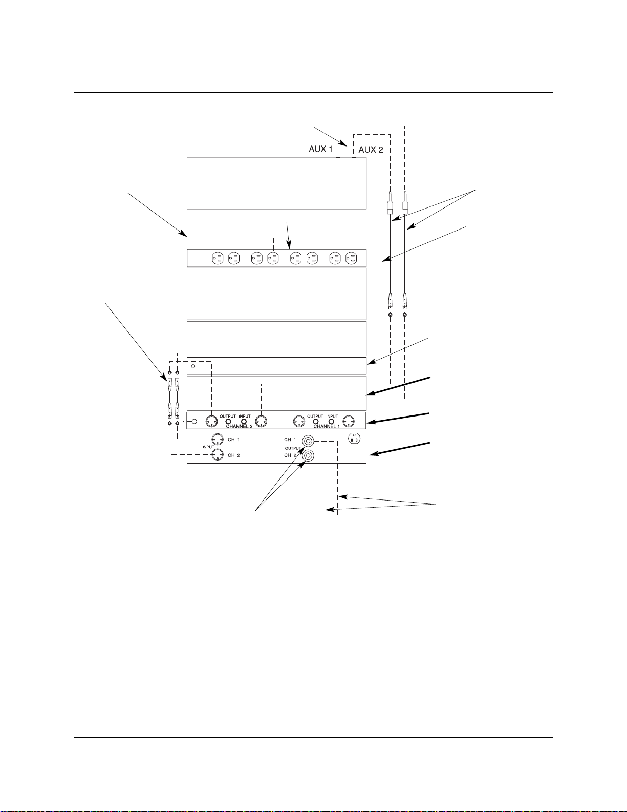
Wenger 500 Series User manual

Owner’s Manual
Audio System Series 500
Stage Monitor Option
©Wenger Corporation 2003 Printed in USA 09/03 Part #126C936-1
Wenger Corporation, 555 Park Drive, P.O. Box 448, Owatonna, Minnesota 55060-0448
Questions? Call.....USA: (800) 733-0393 • International (call collect): (507) 455-4100 • www.wengercorp.com
Thank you for purchasing a Wenger Audio System Series 500 Stage Monitor Option. This document
serves as a quick start guide. Please refer to each manufacturer’s owner’s manual for additional
information. Please contact Wenger Corporation Customer Service with any questions at 1-800-
887-7145.
CONTENTS
Audio System Series 500 Stage Monitor Option — Monitor Loudspeaker cables, internal
cables, and hardware are not shown.
Warranty . . . . . . . . . . . . . . . . . . . . . . . . . . . . . . . . . . . . . . . . . . . . . . . . . . . . . . . . . . . . . . . . . . . . . . . . .2
Manufacture's Owner Manuals . . . . . . . . . . . . . . . . . . . . . . . . . . . . . . . . . . . . . . . . . . . . . . . . . . . . . . . .2
Installation . . . . . . . . . . . . . . . . . . . . . . . . . . . . . . . . . . . . . . . . . . . . . . . . . . . . . . . . . . . . . . . . . . . . . . . .3
Connection Diagram . . . . . . . . . . . . . . . . . . . . . . . . . . . . . . . . . . . . . . . . . . . . . . . . . . . . . . . . . . . .3
Before Starting Installation . . . . . . . . . . . . . . . . . . . . . . . . . . . . . . . . . . . . . . . . . . . . . . . . . . . . . . .3
Install the Amplifier and Equalizer . . . . . . . . . . . . . . . . . . . . . . . . . . . . . . . . . . . . . . . . . . . . . . . . . .4
Connection . . . . . . . . . . . . . . . . . . . . . . . . . . . . . . . . . . . . . . . . . . . . . . . . . . . . . . . . . . . . . . . . . . .4
Setup . . . . . . . . . . . . . . . . . . . . . . . . . . . . . . . . . . . . . . . . . . . . . . . . . . . . . . . . . . . . . . . . . . . . . . . . . . . .5
Initial Graphic Equalizer Settings . . . . . . . . . . . . . . . . . . . . . . . . . . . . . . . . . . . . . . . . . . . . . . . . . .5
Initial Amplifier Settings . . . . . . . . . . . . . . . . . . . . . . . . . . . . . . . . . . . . . . . . . . . . . . . . . . . . . . . . . .5
Power Up Procedure . . . . . . . . . . . . . . . . . . . . . . . . . . . . . . . . . . . . . . . . . . . . . . . . . . . . . . . . . . . .6
Troubleshooting . . . . . . . . . . . . . . . . . . . . . . . . . . . . . . . . . . . . . . . . . . . . . . . . . . . . . . . . . . . . . . . . . . . .6
Replacement Parts . . . . . . . . . . . . . . . . . . . . . . . . . . . . . . . . . . . . . . . . . . . . . . . . . . . . . . . . . . . . . . . . .6

2
WARRANTY
Wenger Corporation will act as a contact and provide support for the Audio System Series 500 Stage
Monitor Option. Call Wenger Corporation Customer Service with any questions or problems at 1-800-
887-7145. While Wenger Corporation will coordinate customer service with each component
manufacturer, the manufacturer of each Audio System Series 500 Stage Monitor Option component is
responsible for that component warranty. There are several manufacturer’s warranty cards
accompanying this manual. It is important to fill out these warranty cards and register each with each
manufacturer within 30 days after receipt of the system.
The warranty for each component is as follows:
Component Warranty
Community XP505 Monitor Loudspeaker 5 Years
QSC PLX1602 Amplifier 3 Years
Rane ME15B Graphic Equalizer 2 Years
MANUFACTURER’S OWNER MANUALS
The following manufacturer’s owner manuals are contained in this binder.
•Community XLT Series Quick Start Manual
•QSC Audio PLX™ Series Amplifier User Manual
•Rane ME15B microGraphic Equalizer Operators Manual

3
CONNECTION DIAGRAM
Left and Right Monitor Outputs
Internal Cable
Existing Amplifier
Power Distribution Unit
Remove the 4-space Drawer
and replace it with a 2-space
Plate at this position.
Series 500 Mixer
120 VAC Power Cord
Monitor Loudspeaker Output
120 VAC Power Cord
Series 500 Audio System Stage Monitor Option Connection Diagram
Insert the Rane Graphic
Equalizer above the new
Amplifier.
Remove the 1-space Plate and
insert the QSC Amplifier into
the Rack at this position.
Existing Graphic Equalizer
Internal Cable Existing
Shelf(501)/CD Player (502)
Existing Feedback Exterminator
Monitor Loudspeaker Cables
INSTALLATION
BEFORE STARTING INSTALLATION
1. Insert this manual and the manufacturer’s Owner’s Manuals (included in the shipping cartons) into
the Audio System Series 500 Binder that came with the Audio System.
2. Please read and understand this entire document.
3. Refer to the illustrations on the following pages. If you need additional information about your Stage
Monitor Option, write, telephone or email Wenger Corporation.
4. Refer to the Manufacturer’s documentation for addition operation information.
5. Fill out the Amplifier and Graphic Equalizer warranty cards with the appropriate serial numbers and
mail to each Manufacturer. These warranty cards must be registered with the manufacturers within
30 days of receipt of the Stage Monitor Option.
6. Before starting the installation, disconnect power from the Series 500 Audio System Power
Distribution Unit (remove the power cord from the 120VAC power source).

4
INSTALLATION CONTINUED
1-space Plate
CONNECTION
1. Using a pair of Internal Cables, connect the Series 500 Mixer AUX 1 and AUX 2 to the Graphic
Equalizer CHANNEL 1 INPUT and CHANNEL 2 INPUT connectors.
2. Connect the Power Cord from the Graphic Equalizer to an unused receptacle on the Power
Distribution Unit.
3. Using a pair of Internal Cables, connect the Rane ME15B Graphic Equalizer CHANNEL 1 OUTPUT
and CHANNEL 2 OUTPUT to the Amplifier CHANNEL 1 INPUT and CHANNEL 2 INPUT connectors.
4. Connect the Power Cord from the Amplifier to an unused receptacle on the Power Distribution Unit.
5. Using the pair of Monitor Loudspeaker Cables, connect the Amplifier CHANNEL 1 OUTPUT connector
to a Community XP505 Monitor Loudspeaker INPUT connector and the Amplifier CHANNEL 2
OUTPUT connector to the other Community XP505 Monitor Loudspeaker INPUT connector.
4-space Drawer
Audio System Series 500
INSTALL THE AMPLIFIER AND EQUALIZER
Refer to the Connection Diagram on page 3 which shows the finished position of the Stage Monitor
Option components and how the components are connected to the Series 500 Audio System.
1. Remove the Screws that attach the 1-space Plate and the 4-space Drawer to the Audio System
Rack. Set aside the screws, the 1-space Plate, and the 4-space Drawer.
2. Attach the 2-space Plate included with the hardware package to the Rack just below the existing
Feedback Exterminator (refer to the illustration below right and on page 3) using four Screws set
aside in step 1.
3. Insert the Rane ME15B Graphic Equalizer into the Rack just below the 2-space Plate.
4. Attach the Graphic Equalizer to the Rack with four Screws (10-32x3/4") contained in the hardware
bag.
5. Insert the QSC PLX1602 Amplifier into the Rack below the new Graphic Equalizer and above the
existing Amplifier.
6. Attach the new Amplifier to the Rack with four Screws (10-32x3/4") contained in the hardware bag.
New 2-space
Plate New Graphic
Equalizer New Amplifier
Before installing Stage Monitor Option After installing Stage Monitor Option

5
SETUP
BEFORE OPERATING
Refer to the Audio System Series 500 Owner’s Manual and the Spirit Series FX16 Users Guide for
additional information regarding set up and component connections.
1. Make sure the Audio System Power Distribution Unit On-Off Switch is in the OFF Position.
2. Connect a power cord from the Power Distribution Unit to a grounded 120 VAC power source. All
components are powered by this component.
3. Connect the QSC PLX1602 Amplifier CHANNEL 1 OUTPUT connector to a Community XP505
Monitor Loudspeaker INPUT connector and the Amplifier CHANNEL 2 OUTPUT connector to the other
Community XP505 Monitor Loudspeaker INPUT connector.
4. Make sure that the QSC PLX1602 Amplifier, the Rane ME15B Graphic Equalizer, and the Series
500 Mixer are connected as outlined on page 4, Connection, steps 1 to 5.
INITIAL GRAPHIC EQUALIZER SETTINGS
Refer to the Audio System Series 500 Owner’s Manual and the Spirit Series FX16 Users Guide for
additional information regarding settings and power up procedures.
1. Make sure that all power switches are OFF.
2. Depress the CHANNEL 1 and CHANNEL 2 BYPASS switches.
3. Place the Level Slide Controls for both channels to the mid-position (0 dBA.).
4. Place the CHANNEL 1 and CHANNEL 2 LEVEL controls at the mid-position (about 12 o’clock).
Level Slide ControlsChannel 1
Bypass Switch Channel 2
Bypass Switch Power Switch
Channel 1 Level
Control Channel 2
Level Control
Channel 1
Overload Indicators Channel 2
Overload Indicators
Rane ME15B Graphic Equalizer Front Panel
INITIAL AMPLIFIER SETTINGS
1. Make sure that the power switch is OFF.
2. Set the CHANNEL 1 and CHANNEL 2 GAIN controls to zero (fully counterclockwise).
Power Switch Channel 1 Gain
Control Channel 2 Gain
Control
QSC PLX1602 Amplifier Front Panel
Clip, 20dB, 10dB,
and Signal LED
Power, Bridge, and Parallel LED

6
SETUP CONTINUED
POWER UP PROCEDURE
1. Connect Power Distribution Unit power cord to a grounded 120VAC receptacle.
a. Power up the mixer, audio sources, or musical instruments. Refer to the Audio System Series
500 Owner’s Manual and other Series 500 component manufacturer’s User Guides for operating
information.
2. Apply a signal to the system and adjust all Audio System components settings to performance
levels.
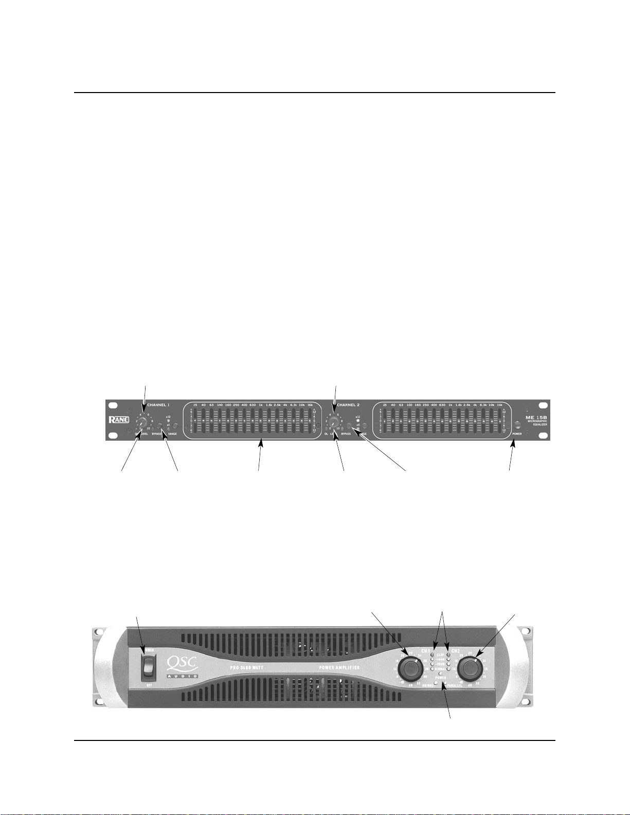
3. Turn on power to the Rane Graphic Equalizer.
a. Make sure that the OVERLOAD indicators are not illuminated. Occasional flashes are normal for
very loud operation. However, if an OVERLOAD LED stays illuminated, reduce the CHANNEL
LEVEL controls.
4. Turn on power to the QSC Amplifier.
a. The yellow CHANNEL 1 SIGNAL and the CHANNEL 2 SIGNAL LED will illuminate if channel input
signals are detected.
b. Turn the CHANNEL 1 GAIN and CHANNEL 2 GAIN controls clockwise until the desired monitor
loudspeaker volume is achieved.
c. Make sure that the CHANNEL 1 CLIP and CHANNEL 2 CLIP LED are not illuminated. Occasional
flashes are normal for very loud operation. However, if a CHANNEL 1 CLIP or CHANNEL 2 CLIP
LED stays illuminated, reduce the CHANNEL 1 GAIN or CHANNEL 2 GAIN level.
5. Release the Rane Graphic Equalizer CHANNEL 1 BYPASS and CHANNEL 2 BYPASS switches (the
upper position).
a. Adjust the Equalizer Bands for channel 1 and channel 2.
b. Compare the signal loudness with the CHANNEL 1 BYPASS and CHANNEL 2 BYPASS switches
pressed and then released.
c. Adjust the CHANNEL 1 LEVEL and CHANNEL 2 LEVEL controls until the signal loudness is equal
when the CHANNEL 1 BYPASS and CHANNEL 2 BYPASS switches pressed and released.
d. Make sure that the OVERLOAD indicators are not illuminated. Occasional flashes are normal for
very loud operation. However, if an OVERLOAD LED stays illuminated, reduce the CHANNEL
LEVEL controls.
6. Check the XL505 Monitor Loudspeakers.
a. The green LED should be lighted indicating that a signal is present.
b. The yellow LED illuminates when the speaker is in the the first stage of protection. This is a
warning to reduce the level.
c. Make sure that the red LED is not illuminated indicating that the speaker is overdriven.
TROUBLESHOOTING
Refer to each manufacturer’s owner manual in the binder for detailed troubleshooting information.
1. Verify all cables are firmly connected.
2. Verify power is supplied to all components. Are there visible lights on each component?
3. Verify channels on the power amplifier are turned up. They should be set about three-quarters of the
way up (turned clockwise).
4. Verify mixer settings are set so that volume sources are loud enough to hear an audible signal.
Audio System Series 500 Stage Monitor Option Qty Audio System Series 500 Stage Monitor Option Qty
Community XL505 Loudspeaker 2Rane ME15B Graphic Equalizer 1
Monitor Loudspeaker Cables 2Internal Cables, XLR connectors 2
QSC PLX1602 Amplifier 1Screw, 10-32x3/4" 8
Internal Cables, XLR connectors to 1/4" connectors 2Plate, 1-space 1
REPLACEMENT PARTS
Other manuals for 500 Series
1
This manual suits for next models
3
Table of contents
Other Wenger Stereo System manuals