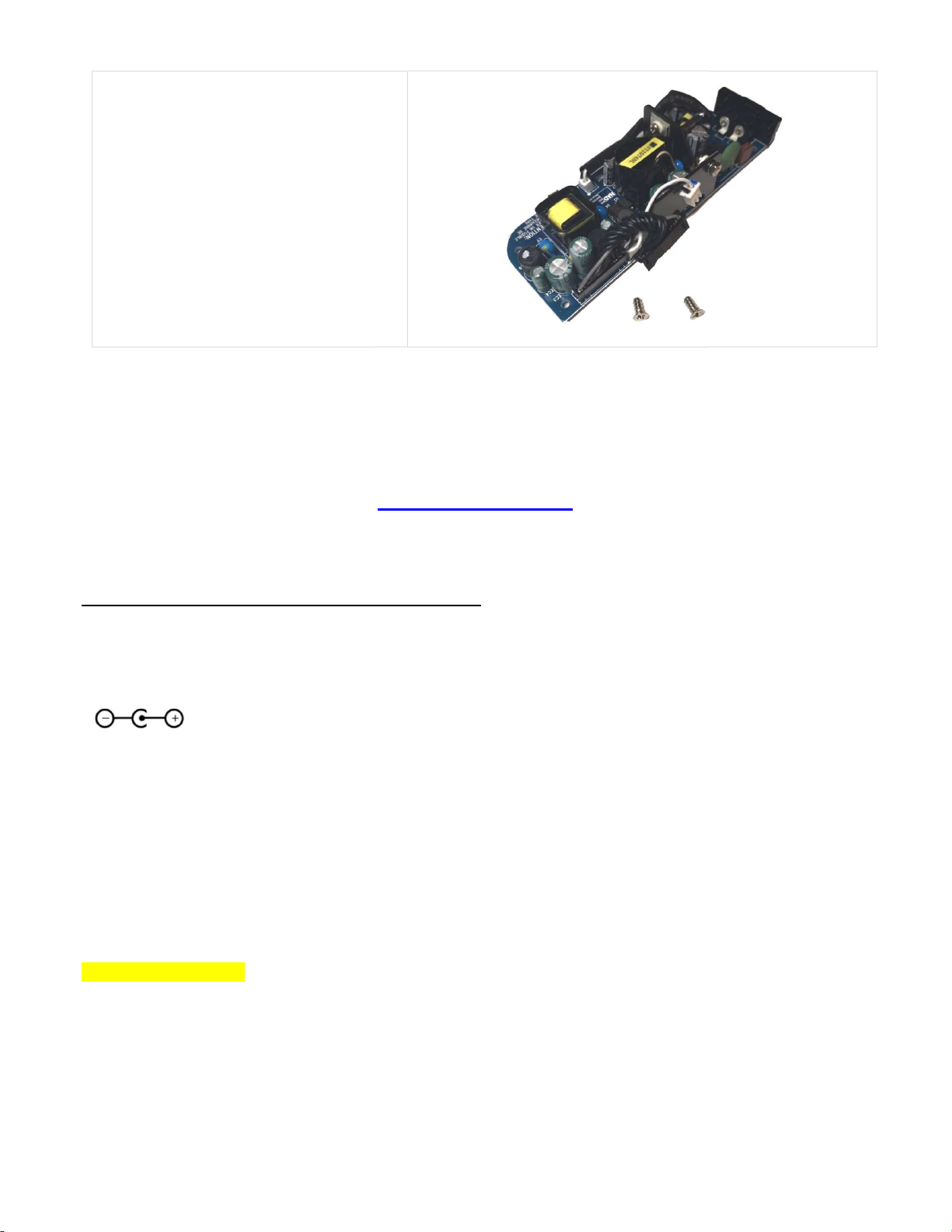
Po zakończonym montażu powinny pozostać:
oryginalny zasilacz oraz dwie śruby. Jeśli
elementy się różnią, sprawdź poprawność
montażu.
After installation should remain: the
power supply and two silver
components differ, check the correct
assembly.
Dziękujemy za zakup tego produktu. Będzie nam niezmiernie miło jeśli odwiedzicie naszą
stronę i zostawicie swoją ocenę produktu.
Thank you for purchasing this product. We will be very pleased if you visit our website and
leave your review on the product page.
Dodatkowe informacje / a
Zasilanie wymagane przez moduł powinno mieścić się w zakresie od 5 do 5.1V.
The power supply required by the module should be between 5 and 5.1V.
Polaryzacja gniazda / Socket polarization:
Specyfikacja / Specification.
napięcie zasilania /
prąd zasilacza /
power supply current: min 2A
zabezpieczenie przeciwzwarciowe /
diody sygnalizujące pracę modułu (
LEDs indicating module operation (
Uwaga !!! / Attention !!!
Moduły są wyposażone w bardzo czułe zabezpieczenia. Aby uniknąć ich uszkodzenia nie dotykać gołą dłonią żadnych
elementów elektronicznych i ścieżek gdy moduł jest włączony do zasilacza. Ludz
o napięciu nawet do 12kV.
The modules are equipped with a
components or paths with your bare hands when the module is plugged into the power supply. The human body can
generate an ESD charge of voltage
Po zakończonym montażu powinny pozostać:
elementy się różnią, sprawdź poprawność
Dziękujemy za zakup tego produktu. Będzie nam niezmiernie miło jeśli odwiedzicie naszą
stronę i zostawicie swoją ocenę produktu.
Thank you for purchasing this product. We will be very pleased if you visit our website and
leave your review on the product page.
www.pd-cf.com
Zasilanie wymagane przez moduł powinno mieścić się w zakresie od 5 do 5.1V.
The power supply required by the module should be between 5 and 5.1V.
DC
power supply current: min 2A
-circuit and overvoltage protection: ≥ 6V
: napięcie sterujące, L2: napięcie właściwe) /
: control voltage, L2: main voltage)
Moduły są wyposażone w bardzo czułe zabezpieczenia. Aby uniknąć ich uszkodzenia nie dotykać gołą dłonią żadnych
elementów elektronicznych i ścieżek gdy moduł jest włączony do zasilacza. Ludz
k
protection circuit. To avoid damaging it
, do not touch any electronic
components or paths with your bare hands when the module is plugged into the power supply. The human body can
Dziękujemy za zakup tego produktu. Będzie nam niezmiernie miło jeśli odwiedzicie naszą
Thank you for purchasing this product. We will be very pleased if you visit our website and
Moduły są wyposażone w bardzo czułe zabezpieczenia. Aby uniknąć ich uszkodzenia nie dotykać gołą dłonią żadnych
rzyć ładunek ESD
, do not touch any electronic
components or paths with your bare hands when the module is plugged into the power supply. The human body can