2
GENERAL INFORMATION
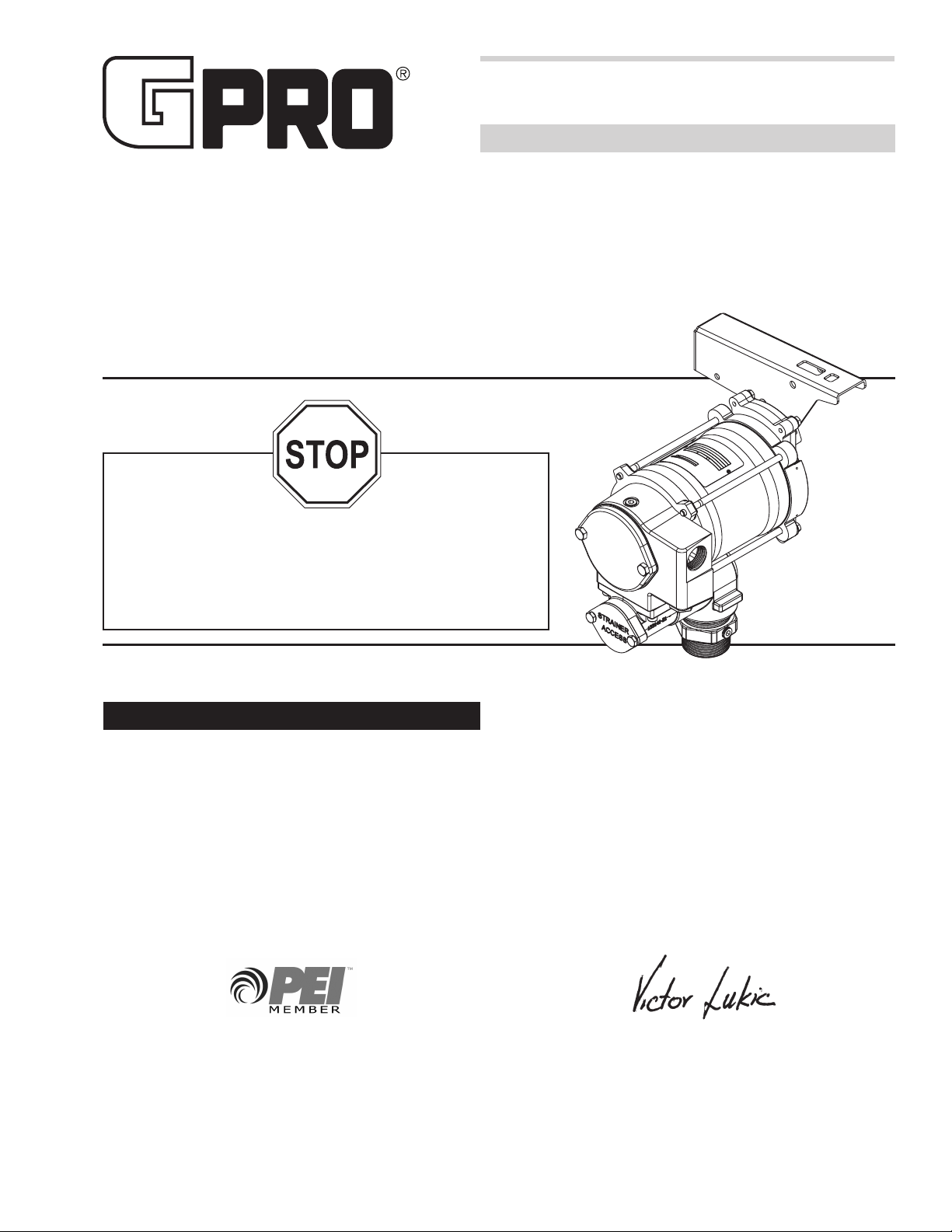
Your fuel pump is designed for use with aviation gasoline
(AVGAS 100LL) and kerosene grade (Jet A). Do not use this
pump for dispensing any uids other than those for which it
was designed. Using the pump with other fuels can damage
components and void the warranty.
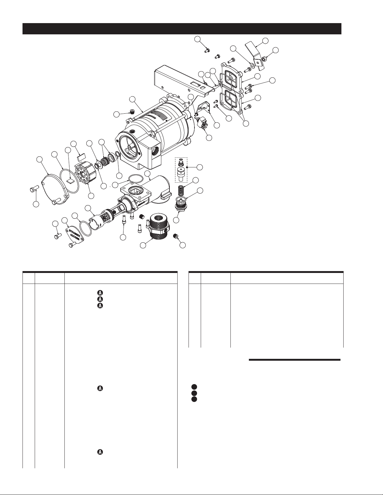
Model Components
PRO20-115PO-AV: Includes pump only and components to
assemble to unit before use.
NOTE: Sufx PO is for ordering purposes only.
For ground-based refueling only. Do not use in or on the aircraft.
WARNING
SAFETY INSTRUCTIONS
The following safety alert symbols are used in
this manual. Obey all safety messages that follow
this symbol to avoid possible injury or death.
DANGER DANGER indicates an
imminently hazardous
situation which, if not avoid-
ed, will result in death or
serious injury.
WARNING WARNING indicates
a potentially hazardous
situation which, if not avoid-
ed, could result in death or
serious injury.
CAUTION CAUTION indicates
a potentially hazardous
situation which, if not avoid-
ed, may result in minor or
moderate injury.
CAUTION CAUTION used without
the safety alert symbol
indicates a potentially
hazardous situation which,
if not avoided, may result in
property damage.
There are inherent dangers wherever ammable fuel and
AC electrical sources are in close proximity.
Static electricity as a source of sparking is always a
concern and requires extreme care in the installation and
operation of your entire fuel transfer system.
Additional components such as meters, automatic nozzles
and lters must be listed for use with fuel transfer systems.
The ow of fuel through a hose and nozzle can generate
static electrical charges and dangerous sparking can
result in re or explosion. Hoses and nozzles must be
electrically conductive and bonded to ground.
It is your responsibility to:
• Know and follow applicable national, state and local
safety codes pertaining to installing and operating
electrical equipment for use with ammable liquids.
• Know and follow all safety precautions when handling
petroleum fuels.
• Ensure that all equipment operators have access to
adequate instructions concerning safe operating and
maintenance procedures.
Appropriate hose, nozzle and suction pipe not
included. Items must meet NFPA 407 guidelines.
For ground-based refueling only. Do not use in or on the aircraft.
For use with aviation gasoline (AVGAS 100LL) and kerosene grade
(JET A).
User should consult NFPA 407 Standard for Aircraft Fuel Servicing
for safety requirements during ground fuel servicing of aircraft
using liquid petroleum fuels. This product has no actual or implied
compliance with this standard.
WARNING
INSTALLATION
Coverplates protect the operator from moving parts. Never
operate the pump without coverplates in place. Never apply
electric power to the pump without coverplates in place.
Always disconnect power before repairing or servicing.
WARNING
Mechanical Connections
All threaded fuel connections must be sealed with thread
tape or a pipe thread sealing compound approved for
use with petroleum fuels and tightened securely to pre-
vent leakage.
Your pump must be mounted on a vented tank. If the
tank is not vented, contact your GPRO™ distributor for
the correct vent cap.
This pump has a built-in check valve to keep the pump
primed. No additional check valve is required on suc-
tion pipes shorter than 15 feet (4.6 meters). Make sure
any check valves or foot valves used are equipped with
proper pressure relief valves.
Your pump is designed to mount directly to a standard 2
in. female tank tting. For the suction pipe, a 1 in. pipe
cut to length and threaded on one end may be used.
Suction pipe should extend to within 3 inches of tank
bottom. Apply thread tape to the suction pipe thread and
securely tighten the suction pipe to the tank adapter. Once
suction pipe is attached to tank adapter, insert suction
pipe into tank and tighten tank adapter to tank tting.
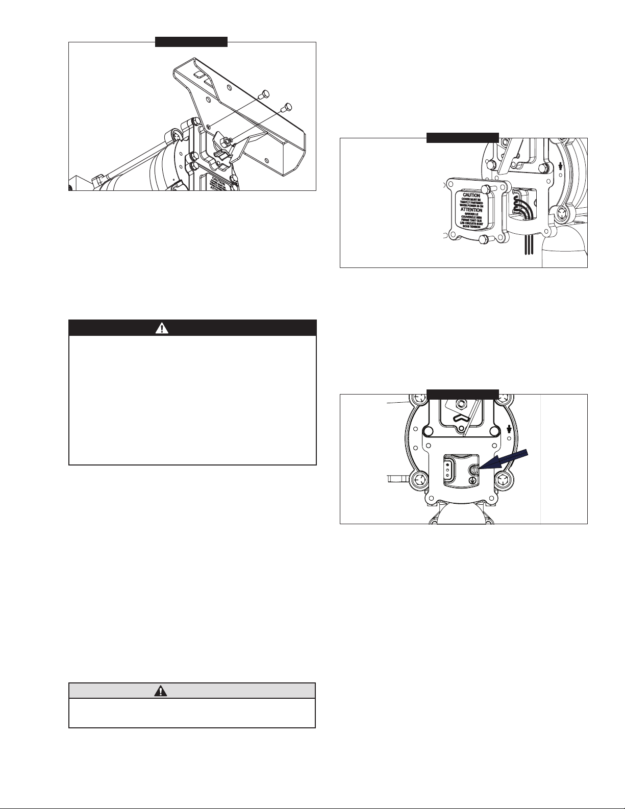
Install Nozzle Hanger
Attention:The nozzle hanger for your pump was removed
before shipping to protect against damage.
To reinstall the nozzle hanger follow the steps below.
1. Remove the two (2) 1/4"-20 x 1/2" bolts from the
switch coverplate.
2. Place the nozzle cover on the switch coverplate and
align holes.
3. Insert the two (2) 1/4"-20 x 1/2" bolts through the
nozzle cover and thread into the switch coverplate.
Torque bolts to 45-60 in/lb (Figure 1).