Permagard PermaSEAL Owner's manual

Page | 1
BASEMENT SUMP AND PUMP SYSTEM
Installation and Operation Guidelines

Page | 2
Contents
1. Product Summary 03
2. Installation Guidelines 03
3. Technical Specification 08
4. Dimensions 08
5. Parts List 08
6. Maintenance 09
7. Health and Safety 09
8. Guarantee 10

Page | 3
1.0 Product Summary
The PermaSEAL Basement Sump and Pump System is specifically designed for the removal of ground water from
cavity drainage membrane systems. The system comprises of an octagonal sump chamber, class leading pump(s),
lock & seal lid and frame, high water level alarm, internal pipe-work, non-return valve and quick release shut-off
valve for quick release of the pump(s) for servicing.
The sump can be used with a single pump or twin pumps via a single discharge line.
The unique octagonal sump shape ensures structural stability and provides eight large surfaces for inlets into the
pump of up to 110mm via an optional wall flange. The sump chamber also features a flared base to prevent
flotation.
The system comes complete with a High Water Level Alarm (Battery), which acts as a warning system to alert the
end user if the water rises above the normal operating level within the tank. The alarm is designed to activate via a
separate float switch inside the tank that is set to activate higher than the activation point of the pump. The panel
contains a battery that will keep the alarm operational in situations of mains power failure.
2.0 Installation Guidelines
It is important to note that these instructions are for guidance only and it is the contractor’s responsibility to satisfy
themselves that the installation procedure is in accordance with the site conditions and good building practice, to
eliminate any potential damage to the system either during or after installation. The installer should also satisfy
themselves that the system can be installed in conjunction with these guidelines, prior to work commencing.
The tank is manufactured from polyethylene and as such is extremely robust. However, as with any preformed tank
they are susceptible to floatation and hydrostatic pressures exerted in high water table conditions.
Please read these instructions in full prior to commencement of the installation. If you are unsure on any point then
please ask for advice before proceeding. Our technical helpdesk is available on 0117 982 3282 from 8:30 –5:00 pm,
Monday to Friday.
1. The PermaSEAL Basement Sump and Pump system is only supplied with the waste outlet pre drilled. The water
inlet(s) and also the electrical conduits will need to be located and drilled before or during the installation of the
sump.
2. Select a suitable location for the pumping station. It is extremely important to site the system with permanent
access in mind for routine maintenance of the system.
3. In all instances the tank MUST be positioned on a flat, level, concrete base of dimensions sufficient to fully
support the base of the tank. Simply lay clean hardcore to the base of the excavation ensuring that it is
consolidated to a thickness of 100mm, then lay a mass concrete to a thickness adequate for the ground
conditions and of minimum 150mm thickness, on top of the hardcore.
4. Carefully position the tank onto the WET concrete base ensuring that no loose debris is inadvertently knocked
into the base, under the tank during this procedure. Push the tank into the wet concrete by 50mm ensuring that
the base of the tank is fully imbedded into the concrete. Position it such that the inlet and outlet pipe work is
correctly aligned.
5. Once the tank is positioned connect the incoming pipe/s to the tank. To do this you must select the location and
drill the appropriate sized inlet suitable for your incoming pipe/s (fitting not supplied).

Page | 4
6. Connecting the internal pipework and the waste outlet:
The PermaSEAL Basement Sump and Pump System is supplied with all of the internal pipe work required to
connect the pump(s) to the external waste outlet.
Firstly we suggest the pump(s) are set up with the waste pipework, float arms and alarm outside of the sump
chamber to ensure correct fitting.
For the single pump system please follow this set up:
1. Use PTFE tape around the thread of the non-return valve then screw the waste pipework to the
connection.
2. Mount the float arm and the high level alarm onto the waste pipe using the jubilee clip (float arm) and
zip tie (high level alarm) provided. As per fig 1.
Fig 1

Page | 5
For the dual pump system please follow this set up:
Fig 2
The dual pump system is designed to have one pump as the master pump and the second as a backup in case of
master pump failure or a sudden water in rush above and beyond the normal volume expected.
It is important to designate the master and backup pump at this point.
1. For both the master and backup pump use PTFE tape around the thread of the non-return valve then
screw the waste pipework to the connection firmly.
2. For both the master and the backup mount the float arm onto the waste pipe using the jubilee clip. As
per fig 1.
3. At this point both pumps will activate at the same time as both float arms are set to their highest
activation point. It is now essential that the rubber grommet at the top of the master pumps float arm is
moved downwards so the master pump activates first (see fig 2).
4. Now install the High level Alarm Switch on the master pump waste pipe just above the pump activation
point. (see fig 2) This will ensure that the alarm will sound if the master pump has activated but cannot
cope with the volume of water entering the chamber or if the pump fails.

Page | 6
5. It is above this point that the activation of the backup pump is set. Normally it is left as the highest
setting on the float arm. (see fig 2)
The system activation process is as follows:
Water enters chamber > master pump activates > high water level alarm activates > backup pump activates.
The activation setting levels may need to be finely tuned when the pumps are in the chamber and water levels can
be tested.
Once the pump or pumps are set up the internal waste pipe connections can be made. Simply screw threaded
connector(s) to the single or double “shut off” valve. The other side of the “shut off” valve has a threaded
connection with two rubber seals and two nuts. These lock the waste pipe through the pre drilled outlet hole and
give a connection for the external waste pipe.
Fig 3 –dual pump set up.

Page | 7
We recommend that the discharge pipe work is 50mm solvent welded Class E PVC pressure pipe. To connect the
discharge pipe work to the discharge spigot on the tank you must firstly screw on the Plain/Threaded PVC Socket
(supplied already attached) onto the spigot which will then leave you with a plain socket to solvent weld your
discharge pipe work into.
To conform with current building regulations, low voltage wiring should not use the same conduit as high
voltage therefore we suggest cutting two 32mm holes to accommodate 32mm conduit into which the pump(s)
high voltage electrical connections should run in one and the High Level Alarms low voltage cable can run in
the other.
It is advisable to run the Pump(s) and High Water Level Alarm cable through the 32mm conduit at this stage. If
the Pump(s) and Alarm are not on site, run a pull cable through the two conduits ready for pulling through the
cables when they are ready to be fitted.
PLEASE NOTE: We suggest that the pump(s) are removed from the sump before backfilling with concrete.
7. In all applications the tank must be backfilled with a mass concrete mix of a minimum 100mm thickness and
used in accordance with the ground conditions ensuring that it is as dry as practical to prevent additional
floatation pressures being exerted on the tank.
The tank MUST be ballasted with water at the same rate as backfilling such that the level difference between the
water and the backfill does not exceed 150mm at any time. Please ensure that when pouring the concrete
backfill, suitable steps are taken to prevent the concrete from entering the tank and drainage channel.
8. Where groundwater is present in the excavation, local de-watering of the ground must be undertaken
throughout the installation procedure until the backfill has fully cured. Please note that the ballast water inside
the tank should not be removed until the backfill has fully cured.
9. It is extremely important that once the tank has been installed and all the inlet connections made, before the
pump is installed and run, the system is flushed through and all sand, silt, rubble and general debris removed
from the tank. FAILURE TO DO THIS WILL INVALIDATE THE WARRANTY ON THE PUMP (S).
10. Once the tank is in position and the discharge pipe work is in place, you must connect the pump to the discharge
line. Simply screw the non return valve and 50mm waste pipe into the pump then connect the female end to the
inline shut off valve.
Electrical Connection
A qualified person in accordance with the Institute of Electrical Engineers Regulations should connect the unit
to the mains supply taking into account all the electrical information provided.
1. The pump should be connected to a 230V 5A fused spur.
2. To conform with current building regulations, low voltage wiring should not use the same conduit as high
voltage. This means the alarm float switch cable should NOT be in the same conduit as the 230V pump cable.
3. Please ensure that there is suitable slack on the cable to allow for the pump to be removed for maintenance.
High Level Alarm
Please see separate installation notes.

Page | 8
3.0 CP250 Pump Technical Specification
Model
CP250
Power Supply
230V AC
Motor Rating
250W
Pump Dimensions
L190 x W140 x H360 (mm)
Max Vertical Output
7m
Max Flow Rate (LPM)
200
Max Liquid Temp.
<50°C
Rated Head (m)
4
Rated Flow (LPM)
130
Discharge Size
1 ½”
Cable Length
5m
Weight
11kg
4.0 Dimensions
5.0 Parts List
•Locked & Sealed Lid & Frame with 46mm recess.
•One or two CP 250 Pumps
•50mm pressure rated pipe-work including a shut off valve and non return pump connection. Single pump
systems have a single ‘in-line’ shut off valve and twin pump systems have a three-way shut off valve to allow
for disconnection of one pump whilst the other is still operational.
•Sump wall discharge assembly that terminates to a 50mm socket outside of the sump ready for 50mm
pressure rated pipe.
•PA50 High Water Level Alarm.

Page | 9
6.0 Maintenance
The PermaSEAL Basement Sump and Pump System requires minimal maintenance, however it is strongly
recommended that the unit is serviced quarterly during the first year. It is essential that the unit is serviced at least
annually thereafter. To clean out the unit you must first turn off the power supply and ensure that it cannot be
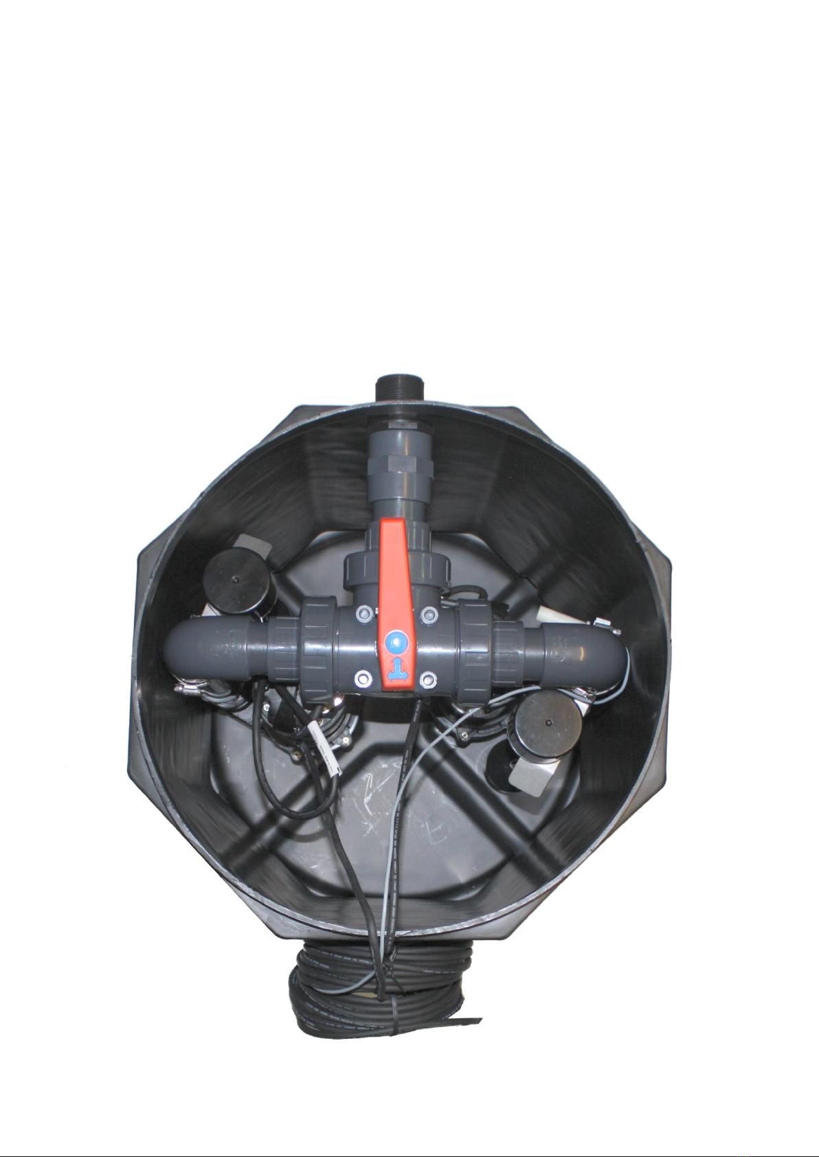
inadvertently turned back on (i.e. remove the fuse). Now remove the access cover to gain access to the pump. Next
you must remove the pump from the tank by disconnecting the pipe work and lifting the pump out. It is advisable to
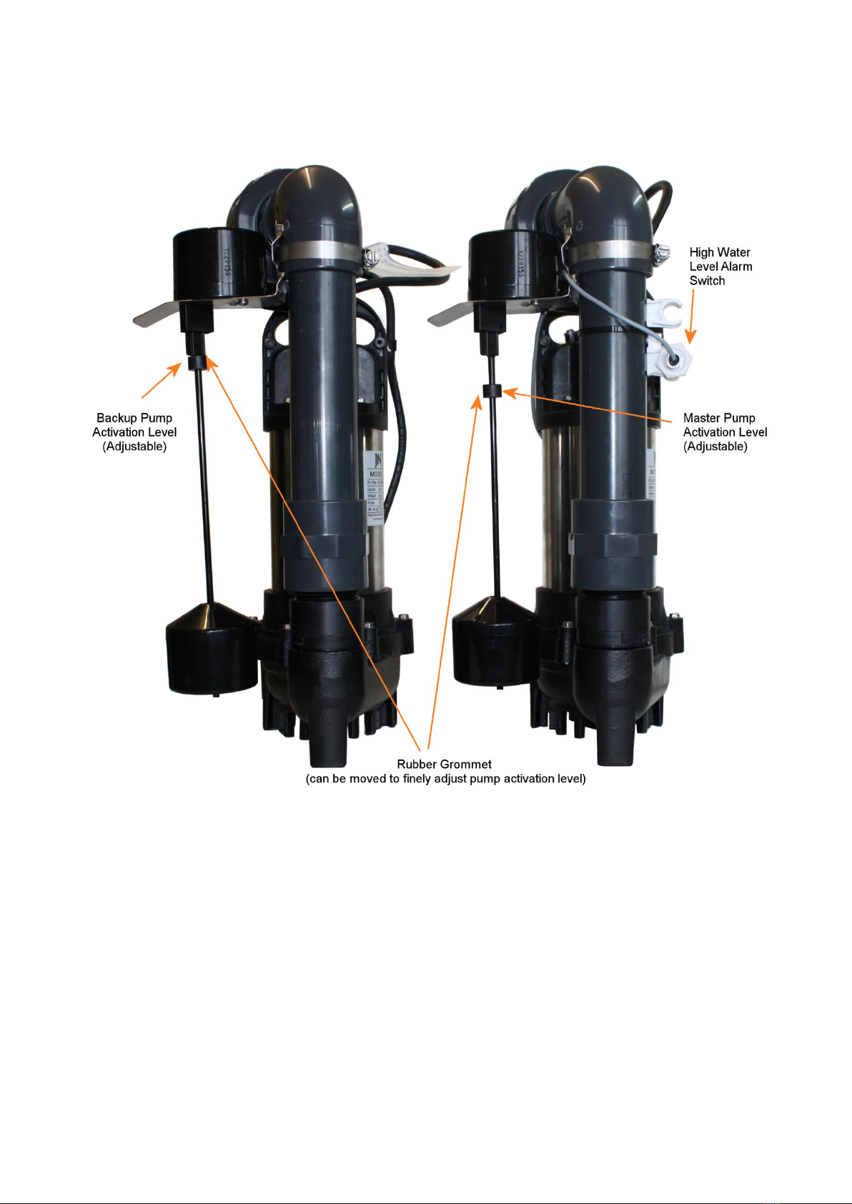
check the underside of the pump to ensure there is no build up of debris around the pump and the float switch as
this can often lead to poor pump performance or damage to the pump itself. You must also clean out the tank
ensuring that there is no debris in the bottom of the tank. Now that the tank is clean you must reconnect the pump
to the pipe work and check the function of the pump prior to replacing the access cover.
Please note that we recommend that the Alarm is tested monthly as per a fire alarm and the battery be replaced
every 2 years.
With dual pump systems it is recommended that the master and back up pump are alternated when the system is
serviced and the backup pump tested.
7.0 Health and Safety
In order to minimise the risk of accidents in connection with the service and installation work, the following rules
should be followed.
•Do not ignore health hazards.
•Observe strict cleanliness.
•Bear in mind the risk of electrical accidents.
•Use a safety helmet, safety goggles and protective shoes.
•All personnel who work with sewage systems must be vaccinated against diseases to which they may be
exposed.
•A first aid kit must be close to hand.
•Note that special rules apply to installations in an explosive atmosphere.
•Special note should be taken to site health and safety warnings.
Electrical Connections
•The following works should only be done by qualified and authorised electricians.
•Permagard disclaim all responsibility for work done by untrained and/or unauthorised personnel.
•Heed operating voltage (see name plate and additional labels).
•Take out the main fuses to isolate the mains supply from the control unit before repairs or any other
works and ensure it cannot to energized again.
•As the pump is equipped with an automatic level control, there is a risk of sudden restart.
•Before starting check the efficiency of the protective arrangements of the pump and the monitoring
equipment. Failure to heed this warning may cause a lethal accident.
•Do not put the lead ends into water! Irruption of water may cause malfunctions.
•If persons are likely to come into physical contact with the pump or pumped media, the earthed (grounded)
socket must have an additional connection to an earth (ground) fault protection device (GFI).
•Use the pump only in accordance to the date stated on the pump’s plate.
•Connection only to mains supply installed in accordance to the local regulations. For fusing of D.O.L.
•Starting pumps use only appropriate slow fuses or automatic circuit breakers with D characteristics. This is
because the motor’s nominal voltage is measured at the terminal board of the pump; please consider the
voltage drop of long supply cables.
•Replace the cable if the cable jacket is damaged. Do not pinch the cable or pull it around sharp bends.
•Always install the control unit in a dry and well ventilated room. Never install the control unit within the
tank.

Page | 10
8.0 12 Month Component Guarantee
If within the guarantee period of a product any defect is discovered in respect of workmanship, construction or
material, we will make good the defect or replace the defective part at our expense inside normal working hours at
the company’s premises providing, written notice is given immediately the defect is discovered and that, if required
by us, the part or complete unit is returned to the company’s premises carriage paid. Spares or repaired parts are
delivered ex works exclusive of fitting. The guarantee does not apply to defects caused by incorrect installation,
abnormal conditions of working, accidents, misuse or neglect. Our responsibility is in all cases limited to the cost of
making good the defect or replacing the defective part at the company’s premises inside normal working hours. We
exclude all liability for any consequential or other damage or losses which may occur. We will not be liable if the
pumping system fails due to it having been incorrectly specified (e.g. where the pump is inundated due to an
inadequate waterproofing design or where the pump is used to discharge inappropriate media).
All Permagard products are of a high quality and subject to rigid quality control. The company, however, cannot govern the conditions of usage and application of its products and any warranty,
written or implied covers material only. The information contained in this leaflet is given in good faith but no liability can be assumed by the Company for any damage, loss, injury or patent infringement
arising from its use.
Permagard Products Limited Chittening Industrial Estate, Avonmouth, Bristol. BS11 0YB.
T: 0117 982 3282 W: www.pemagard.co.uk E:sales@permagard.co.uk
Table of contents