PFS Dry-Vac Series User manual

INSTALLATION AND
OPERATION MANUAL
DRY – VAC SERIES
PREMIER FLUID SYSTEMS INC.
BURLINGTON ONTARIO, CANADA
PHONE (905) 637-2611
FAX (605) 333-4722
www.pfspumps.com

INSTALLATION AND
OPERATION MANUAL
DRY – VAC SERIES
IMPORTANT INFORMATION:
Please read this manual before operating your dry screw vacuum pump.
INDEX
1.0- General Construction
1.1 General
1.2 Construction
1.3 Specifications
1.4 Piping diagram
1.5 Purges
2.0- Handling Process
2.1 Assembly Of Piping
2.2 Piping
2.3 Preparation for Operation
2.4 Operation
2.5 Stopping
2.6 Lubrication
3.0- Maintenance and Inspection
3.1 General
3.2 Periodical
3.3 Maintenance and check list
4.0- Trouble shooting
5.0- Vacuum system check list
2

1.0- GENERAL CONSTRUCTION
1.1 General
This Dry Vacuum pump compresses the incoming gas by means of two screw rotors, having a
profile comprising plurality of curves, i.e. Archimedean curve, Quimby curve and arc, which
rotate smoothly with a certain clearance maintained between each other and the inside wall of
the casings.
The pump is so constructed as to allow no oil to be mixed with the handled gas.
The power of motor is transmitted to the main rotor shaft through a V-Pulley or a coupling
device, and further to the driven rotor shaft through a timing gear.
1.2 Construction
●Screw Shaft
The Screw shaft is made of high grade ductile cast iron. The screw shaft had been through
precision machining done by a numerically controlled special machine. The screw shaft will
have a perfect dynamic balance after machining.
●Timing Gear
The timing gear is the most important part of the screw vacuum pump, and it is necessary for
turning the rotors with a certain clearance kept from each other. The gears tooth surface is heat
treated, and then polished with a special high precision tooth polishing machine for noises
control.
●Bearing
The bearing on fixed side is an angular contact ball bearing and that on free side is a roller
bearing of heavy load capacity. These bearings have been selected as to stand high speed and
heavy service load and to assure clearances between gears and Screws are maintained.
●Shaft Seal
The shaft seals consist of Shaft Lip Seals on Suction side, mechanical Seal and Viton Oil Seal
on Discharge side.
●Oil level Gauge
Oil Level Gauge is located at Front End Cover. Oil should be supplied to the top level of Center
Line. If the oil level is too low, Gear, Bearing and Mechanical Seal will be damaged as a result of
improper lubrication. While pump is not running, check the oil level and/or contamination then.
Refill or change the oil if needed. The oil is splashed over by rotation of timing gear to lubricate
bearings and Mechanical seals.
3

1.3 Specification
Dry-Vac Type
Specification
200 300 400 800
Normal Displacement
60Hz (M³/Hr) 200 300 400 800
Ultimate Pressure (Torr) 0.1 0.05 0.05 0.01
Power KW (60Hz) 7.5 11 15 22
Rotation (RPM) (60Hz) 3500
Suction(A) 40 50 65 100Port size (mm)
Discharge(A) 40 40 50 65
Cooling Water (L/Min) 3.0 7.6 7.6 10
Weight (Kg, Pump Only) 260 320 385 820
●Note
(1) Synthetic and mineral type of oil can be used.
For shipping, we supply pure mineral gear oil.
(2)Above listed amount of Cooling Water is based on water temperature 20℃. So, the amount
of water may vary when using warmer water.
1.4 Piping Diagram
VACUUM IN (Suction)
COOLINGWATEROUTLET
AIRFILTER SILENCER AIRVENT
AIRCOOLER
DRY SCREW PUMP
COOLING WATER
INLET
<OPTION>
1.5 Purges
●Cooling Purge
This purge is intended to cool the Screws and inside of casing.
During the operation of the pump, this purge is required to cool down compression heat of
discharged process gases. The process gases introduced into the casing from the suction side
are compressed by the rotation of the screw and transferred to discharge side. This ompression
process generates heat and will be transformed to gases. Since this compression heat reaches
above 130℃∼200℃in discharge side, we need cooling purge to cool down this heat.
4

(1) Purge flow
Dry-Vac Model Amount (㎥/min N) Remark
200 0.55
300 0.55
400 0.8 ~ 0.86
800 Above 1
This purge amount can
Vary as per the pump’s vacuum level
(2) Type of Cooling Purge
①Standard : Atmosphere purge through air filter
②Using Heat Exchanger : Recycle process gases from discharge after cooled through the
heat exchanger.
③Using Inert gases like N2 etc. Instead of atmosphere or cooled process gas.
●Sealing Purge
This purge is required during the operation and intended to pressurize the front end cover with
Inert gas like N2 so that the process gas or fluid can not enter into the timing gear set and
bearings. You can use either one of two plugs provided on the top of Front End Cover for this
sealing purge connection.
The purge pressure is below 0.5㎏/㎠G and the leak rate for our Mech. seal is below 3cc/Hr.
Also our Mechanical seal can seal pressure up to 3㎏/㎠G.
●Cleaning Purge
This purge is required to clean inside the pump before stopping the pump. Before stopping the
pump, purge N2 gas, steam or cleaning agent for 20 to 30 minutes after closing the main valve
on suction side to clean sticky process materials or process gases. This purge is important
when pumping corrosive/toxic gases or sticky materials like resin.
●Pump Steam Flushing
After each process, run the pump for 10∼20 minutes without load after close main suction
valve (Dry run, Cleaning purge).
This is to remove & clean process gases / condensed vapors the pump during the process.
These process materials build up inside the pump can be the reason for pump overload when
restart the pump for next process.
Also, when restart the pump after a certain period later, these process materials can be cause
for pump seizure or overload.
In this case, flush steam the pump internals & Screws with following procedure instead of
rotating the pump with force.
◐Steam Flushing Method (after operation)
(1) Process materials that require Steam flushing: Monomer, Polymer, Resin, etc.
(2) Steam pressure: approx. 1 ㎏/㎠G
(3) Flushing Procedure
5

①Close Suction valve, Open discharge valve or Silencer/ Separator's Drain valve
②Inject Steam for 1∼10 minutes (the injecting time varies with process material) through
pump suction line or through a plug in suction flange
③Try to rotate shaft (Pulley or Coupling) by hand to see whether the pump rotate smoothly or
not (This time, be careful not to start the motor)
④If the pump move smoothly, stop injecting steam.
Then, start motor and check if the pump runs normal or not.
(4) If not satisfied with above procedures, repeat the procedures 2∼3 times more.
2.1 Assembly of Piping
2. HANDLING PROCEDURE
●Location
(1) Mount the Pump on a clean, flat & level surface of sufficient rigidity. If it should be installed
outdoor, check motor, V-Belt and other part are for outdoor service.
(2) There should be enough space for maintenance like dis-assembly, re-assembly and
periodical inspection. etc.
●Foundation
(1) The foundation concrete should have an adequate pressure bearing area, in consideration
of pump weight and a withstanding pressure of the soil. The mix ratio of the concrete is 1-
cement, 2-sand and 4-gravel.
(2) In order to embed anchor bolts in the concrete, the foundation must have holes of good size,
and its surface should be as even as possible.
(3)Upon confirmation that the concrete has hardened, proceed with assembly of piping.
●Installation
(1) Mount the pump horizontally and center it on base plate in accordance with the instruction
manual.
(2) Place the pump on the base plate, and support the base plate equally so that the bed will be
horizontal and also a space for grouting the cement mortar is available between the foundation
surface and the bed.
(3) Put anchor bolts in place on the bed preliminarily, set nuts on the full head of bolts, and
leave them pendulous in the bolt holes. At this time, if the bed is supported locally, it could be
deformed, notwithstanding its strength.
(4) Assure the level by using a level gauge:
Check the levelness on the machined surface. The levelness should be limited to 0.5mm in any
one meter.
(5) Grout the cement mortar made up from 1-cement and 2-sand in the space under the bed
and in anchor bolt holes, and keep for few days. Upon hardening of the mortar, tighten the nuts
for anchor bolts. Check pump & motor alignment.
6

2.2. Piping
●Main Piping
(1) Clean inside of suction and discharge pipe to be free from rust, dust and foreign matters,
and place a strainer of 40 mesh on or over suction side.
(2) It is advisable to install expansion joint on the suction side as well as the discharge side of
the pump. Also, provide supports for piping so that no excessive load will be imposed on the
pump.
(3) In case Silencer is provided on discharge side, install it as near to connection as possible.
(4) Be sure to install a Non-return Valve adjacent to the suction port so that the pump will not
turn reversely. If preferred, install a gate valve instead, and assure to shut off prior to stopping
the pump.
(5) In case, there is a risk of condensate gas being collected on the pump discharge pipe, install
a recovery tank under the pump, then the condensed gas and water will be collected during
operation and can be discharged by opening of drain valve.
(6) Drain receiver should be installed under the drain valve to collect the discharged liquid.
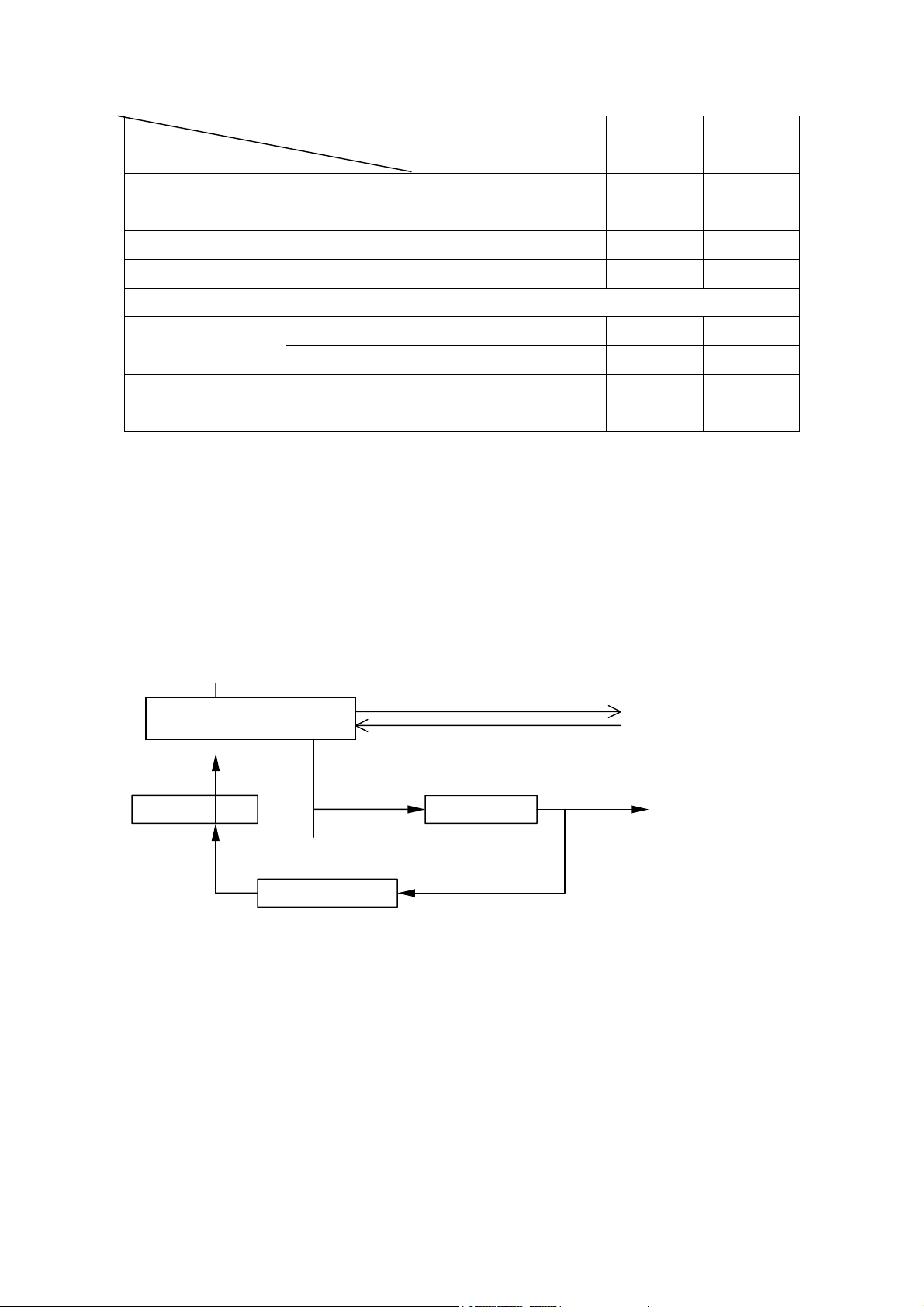
●Cooling water piping
Cooling water piping is required to cool pump Front End plate & Casing. This piping should be
assembled with reference to the piping diagram and the outline drawing .
2.3 Preparation for Operation
(1) Remove dust and foreign particles such as welding slug from Vacuum pump and Piping.
(2) Check all suction and discharge connections are properly tightened and all piping properly
supported. Check cooling water piping as well.
(3) Fill oil up to the red point of the oil gauge. If oil is low, gear and bearing can seize, and if oil
is too high, the temperature will rise excessively, and can be cause for gear noise or other
negative effect on other parts.
(4) Let cooling water flow as specified in chart 1.3.
2.4 Operation
(1) Open suction valve, and turn on the power under no load condition to check rotating
direction. At this time, start up instantly.
(2) Run the pump under no load condition for 20-30 minutes to check any abnormal vibration or
heat. In case of any abnormality, stop operation and search for the cause. Often the cause is
improper installation or failure of alignment.
(3) Run the pump for 2-3 hours under normal load condition and check the temperature and
vibration.
(4) During operation, pay attention to level of Ampere drawn by the motor.
If case of abnormality, stop the pump immediately and check for cause. Often, the cause is
interference between rotors or between the periphery of rotor and the inner surface of casing.
All pumps are tested prior to shipping. However, full care and inspection is still necessary after
7

the pump is disassembled and reassembled at site.
◐Caution during Operation
1. Check temperature of bearing & lubricant and indication of Ampere Meter & cooling water.
2. Keep operation within designated specifications.
2.5 Stopping
(1) Shut off main valve on suction side.
(2) If any corrosive gas has been inhaled, introduce the atmosphere air to suction side for 20-30
minutes before stopping to clean inside of pump.
(3) Stop the pump by turning off the motor.
(4) Shut off cooling water.
If freezing is anticipated, drain water from pump by opening Drain Valves.
2.6 Lubrication
Lubricants to be used must be good quality high grade petroleum products containing oxidation
inhibitor, rust preventive, extreme-pressure additive, etc. (Do not use any lubricant which
contains any element of water, sulfate resin or tar.)
Turbine oil (ISO VG68) readily obtainable in the market will generally satisfy these requirements.
The following brands are recommended for use as lubricants for gear and bearing.
●Lubricant:
BP, Energol THHT 68
BP, Energol THB 68
Petro-Canada, R & O 68
Shell, Turbo 68
Mobil, Gear 626
or, equivalent.
●Grease :
G 40M (SHIN ETSU)
JFE 552 (NOK-KLUBER)
3. MAINTENANCE AND INSPECTION
3.1 General
(1) During operation, the temperature will rise corresponding to the compression ratio due to
compression heat. However, if the temperature rise is local and the outside coating scorched, it
is abnormal. It may be because of the improper cooling water supply or cooling water cut-off,
interference of Screw with casing or the pump has sucked in some foreign material. Therefore,
stop the operation immediately to check the condition.
8

In some case, the Screw and the casings might have corroded due to lengthy operation, this will
result in larger clearance between these parts with gas slippage from discharge gas to suction
side in large quantities, the pumping capacity of the pump will less than originally planned. In
such cases, the pump capacity has shown a steady decreased..
It is recommended to stop the pump and take measurements of the clearances for any
consideration of corrective action to be taken.
(2) Abnormalities can be noticed immediately by making routine checks on bearing temperature,
vibration or noise.
(3) Interference between Screws or between Screw and casing can be noticed by listening to
any sound through stethoscope applied against the casing. Make checks from time to time.
(4) In winter, in cold regions, whenever the pump is stopped, let cooling water drained. Freezing
of water could damage the pump jacket.
3.2 Periodical checks
●Daily
(1) Oil-Level Gauge: Excess or low lubricant level can damage gears and bearings.
(2) Check that the amount of cooling water is adequate.
(3) Check the temperatures of Grease cover and Front End Cover.
Use of suitable thermometer or of surface thermometer will be convenient.
(4) Check the suction and discharge pressures. To check these pressures, make sure that the
operation of the pump is within specifications.
(5) Check load on the motor.
Be aware that an increase in the motor load indicates some kind of abnormality.
●Monthly
(1) Check tension of V-belt (if any).
(2) Check lubricant color. (If Oil color is dark, replace lubricant).
(3) Check Oil level. If Oil disappears constantly, check Mechanical Seal.
●Quarterly
Check Cooling water flow & color. If something wrong, clean water jackets and water
piping.
●Every 6 Months
(1) Check pipe supports for the pump.
(2) Replace lubricant in the Front End Cover.
3) Replace grease in the Rear End Cover.
●Yearly
(1) Check Mech. seals.
(2) Check inner surface of Screws and casing.
Disassemble the piping on suction side to check the inner surface of screws and casing.
(3) Check the gear- Remove the Front End Cover to check the gear.
9

3.3 SCREW VACUUM PUMP MAINTENANCE AND CHECK LIST
No. Item Check Point Daily Monthly 3~6 Month Yearly
1 Ampere of Motor Any Change?
Ampere as specified?
0
2 Rotation Is rotation smooth and
Correct?
0
3 Suction and
Discharge Pressure
Are pressures as Specified? 0
4 Noise and Vibration Any abnormal sound or
Vibration
0
5 Temperature Any excessive oil temperature
rise on Bearing and other parts?
0
6 Oil amount of Front
End Cover
Is Oil at proper level? 0
7 Water contamination
On Front End Cover
Clean or not? 0
8 Oil Leak Oil not leaked? 0
9 Lubricant Replacement Replace All Oil & Grease in Front
end Cover & Grease cover.
0
10 Flow and Pressure of Cooling
Water for Pump Casing
The amount as specified?
The pressure not too high?
0
11 Suction and Discharge pipe Is there any Scale? 0
12 Cleaning and Dry
Run at stop
Before stopping the pump after
Each batch, Close main Valve
on suction side, run for 20~
30min. while purging N²or air
13 Check Casing and Rotor Any rust or flaw found? 0
14 Lip seal, Oil seal, Bearing, O-
ring, Slip sleeve, Packing
V-Belt/Coupling
Replace when need. 0
10

4. TROUBLE SHOOTING
PROBLEM CAUSE SOLUTION
Insufficient
Air quantity
ㆍFilter is clogged
ㆍToo much Clearance
ㆍClean or Change FILTER
ㆍCheck Clearance
Overload on
Electric Motor
ㆍForeign matter are caught in
ㆍ P re ssure lo ss in P ipin g is inc rea sed
(increase in Suction Pressure)
ㆍinterference between screws.
ㆍinterference between Screw and Casing
ㆍDischarge with Cooling water flow
ㆍClean or Change Filter
ㆍAdjust or Replace the Screw and
Casing
ㆍCheckthepressuredifference
between Inlet and Outlet
ㆍAdjust improper Screw clearance.
Adjust Timing Gear
ㆍMake the Side Clearance larger /
Make the clearance between Screw
and Casing larger.
ㆍDrain & clean Discharge line
Overheat
ㆍExcessive lubricant in Front End Cover
ㆍVacuum Pump inlet temperature high
ㆍToo much Compression ratio
ㆍInterference between Rotor and Casing
ㆍProblem with Cooling water flow
ㆍCheck Oil level
ㆍCheck suction & discharge pressure
ㆍSearch for the cause of interference
ㆍClean Cooling water kline
Knocking
ㆍInterrelated position between Timing
Gear and Rotor is incorrect
ㆍImproper assembly
ㆍAbnormal rise in pressure
ㆍDamage on gear due to overload or
improper lubric ation
ㆍReposition
ㆍReassemble
ㆍ Search for the cause
ㆍReplaceTimingGear
Bearing or
Gear damaged
/Shaftbroken
ㆍImproper lubricant
ㆍLubricant runs short
ㆍOverload
ㆍChange lubricant
ㆍRefill lubricant
ㆍReplace the Shaft
※If the troubles are not resolved by the above mentioned actions, the cause may possibly be
located in Pump operation condition. In such case, please contact us with the following
information.
1. Model Name & Number Serial Number, Application, etc.
2. Information of Piping (Valve, Strainer, Number of Bends, etc.)
11

5. VACUUM SYSTEM CHECK LIST
CHECK LIST CHECKS
Open cooling water supply valve. Is it flow properly?
Close Vacuum suction line
Open discharge line
Check lubricant color and level. Is it acceptable?
Check Belt tension (for V-belt type only), coupling alignment
Before
Operation
Run Vacuum pump for few minutes before open the suction line
Check vacuum level in full vacuum. Is it normal?
Check electrical connections (voltage & amperage) in full vacuum.
Is it normal?
Any abnormal noise?
Check operation temperature. Is it normal?
During
Operation
Check lubricant color and level. Is it acceptable?
Run Vacuum pump for few minutes after closing suction line.
If foreign material is introduced inside of vacuum pump, clean it with
cleaning agent.
Drain cooling water from vacuum pump if the pump is stopped for long
time
Make sure that suction & discharge line is closed
Stopping
Make sure power supply is closed
12

13
OUR PRODUCTION
SINGLE STAGE CENTRIFUGAL PUMPS
MAGNETIC DRIVE
SINGLE STAGE CENTRIFUGAL PUMPS
SELF-PRIMING PUMPS
MULTI STAGE CENTRIFUGAL PUMPS
LIQUID RING VACUUM PUMPS
LIQUID RING COMPRESSORS
VACUUM PUMP PACKAGES WITH PARTIAL
OR TOTAL SERVICE LIQUID RECOVERY
PRINTED IN CANADA
DRY-VAC SERIES-MANUAL
TRAVAINI PUMPS OBJECTIVE is to continually improve its product through research and development; therefore we reserve the right to make changes without
prior notice.
PREMIER FLUID SYSTEMS INC.
4460 HARVESTER ROAD
BURLINGTON, ONTARIO L7L 4X2
℡(905) 637 2611 or (905) 333 3099
TOLL FREE (800) 461 2611
(905) 333 4722
e-mail: [email protected]
www.pfspumps.com
This manual suits for next models
4
Table of contents
Popular Water Pump manuals by other brands

GORMAN-RUPP
GORMAN-RUPP AMT 5760-95 Specifications information and repair parts manual

Binks
Binks Maple 15/6 Service manual

Quincy Compressor
Quincy Compressor QSVB Series instruction manual

Xylem
Xylem FLYGT 2640.181 Service and repair instructions

AirTech
AirTech 3AV95 Repair instructions

Edwards
Edwards Microvac 149-HS instruction manual