Phase Linear PCD161A User manual

T
U
N
I
N
G
DISP
AUX IN
SCN
MODE
PCD161A
BAND
PCD161A
Owner's Manual/Manual del Usario/Manual de L'Utilisateur
AM/FM/CD Receiver
Receptor AM/FM/CD
AM/FM/CD Ampli-Syntoniseur

PCD161A
2
PREPARATION
Getting Started
It’s a good idea to read all of the instructions
before beginning the installation.
Contents
Installation Instructions.............................. 3
Wiring ........................................................ 5
Installing the Removable Faceplate .......... 6
Operating Instructions ............................... 7
CD Player Operating Instructions.............11
Care and Maintenance............................ 13
Specifications .......................................... 14
Installation Requirements
This unit is designed for installation in cars,
trucks and vans with an existing radio opening.
In many cases, a special installation kit will be
required to mount the radio to the dashboard.
These kits are available at electronics supply
stores and car stereo specialty shops. Always
check the kit application before purchasing to
make sure the kit works with your vehicle. If you
need a kit but cannot locate one, call our
customer support line at 1-800-323-4815.
(U.S.A. and Canada only.)
Tools and Supplies
The following tools and supplies are needed to
install the radio.
• Torx type, flathead and Philips screwdrivers
• Wire cutters and strippers
• Tools to remove existing radio (screwdriver,
socket wrench set or other tools)
• Electrical tape
• Crimping tool
• Volt meter/test light
• Crimp connections
• 18 gauge wire for power connections
• 16-18 gauge speaker wire
Speaker Requirements
Only connect speakers rated with a load
impedance of 4 ohms. Speakers with a load
impedance of less than 4 ohms could damage
the unit.
Disconnect Battery
Before you begin, disconnect the battery
negative terminal.
Toll-Free Installation Assistance
If you require assistance, contact Technical
Support at 1-800-323-4815 from 8:30 a.m. to
7:00 p.m. EST Monday through Friday and from
9:00 a.m. to 5:00 p.m. EST on Saturday.
(U.S.A. and Canada only.)
Pour des instructions en Francais, référez-vous à la page 30.
Para obtener instrucciones en Español, diríjase a la página 16.

PCD161A
3
INSTALLATION INSTRUCTIONS
Installation Using a Mounting
Sleeve
1. Slide the mounting sleeve off the chassis. If
it is locked into position, use the removal
tools (supplied) to disengage it.
2. Check the dashboard opening size by
sliding the mounting sleeve into it. If the
opening is too small, carefully cut or file as
necessary until the sleeve easily slides into
the opening. Do not force the sleeve into the
opening or cause it to bend or bow. Check
for sufficient space behind the dashboard for
the radio chassis.
3. Locate the series of bend tabs along the top,
bottom, and sides of the mounting sleeve.
With the sleeve fully inserted into the
dashboard opening, bend as many of the
tabs outward as necessary to firmly secure
the sleeve to the dashboard.
4. Place the radio in front of the dashboard
opening so the wiring can be brought
through the mounting sleeve. Follow the
wiring diagram carefully and make certain all
connections are secure and insulated with
wire nuts or electrical tape. After completing
the wiring connections, turn the unit on to
confirm operation (vehicle ignition must be
“on”). If the unit does not operate, re-check
all wiring until the problem is corrected.
5. Make sure the radio is right-side up, then
carefully slide the radio into the mounting
sleeve until it is fully seated and the spring
clips lock it into place.
6. Attach one end of the perforated support
strap (supplied) to the screw stud on the rear
of the chassis using the hex nut provided.
Fasten the other end of the perforated strap
to a secure part of the dashboard either
above or below the radio using the screw
provided. Bend the strap to position it as
necessary.
7. Test the radio using the Operating
Instructions that follow.
T
U
N
I
N
G
DISP
AUXIN
SCN
MODE
PCD161A
BAND
CAUTION: The support strap
must be used to prevent
damage to the dashboard from
the weight of the radio or
improper operation due to
vibration.
CAUTION: For proper operation
of the CD player, the chassis
must be mounted within 20° of
horizontal. Make sure the unit is
mounted within this limitation.
BEND TABS
INSTALLATION

PCD161A
4
INSTALLATION INSTRUCTIONS
Installation Using a Kit
If your vehicle requires the use of an installation
kit to mount this radio, follow the instructions
included with the installation kit to attach the
radio to the mounting plate supplied with the kit.
1. Wire and test the radio as described in step
4 of “Installation Using a Mounting Sleeve”.
2. Install the radio mounting plate assembly to
the sub-dashboard according to the
installation kit instructions.
3. Attach the support strap to the radio and
dashboard as described in step 6 of
“Installation Using a Mounting Sleeve”.
4. Replace the dashboard trim panel.
ISO Installation
This unit has threaded holes in the chassis side
panels which may be used with the original
factory mounting brackets of some Toyota,
Nissan, Mitsubishi, Isuzu, Hyundai and Honda
vehicles to mount the radio to the dashboard.
Please consult with your local car stereo
specialty shop for assistance on this type of
installation.
1. Remove the existing factory radio from the
dashboard or center console mounting.
Save all hardware and brackets as they will
be used to mount the new radio.
2. Carefully unsnap the plastic frame from the
front of the new radio chassis. Remove and
discard the frame.
3. Remove the factory mounting brackets and
hardware from the existing radio and attach
them to the new radio.
CAUTION: Do not exceed M5 X 6 MM screw
size. Longer screws may touch and damage
components inside the chassis.
4. Wire the new radio to the vehicle as
described in step 4 of “Installation Using a
Mounting Sleeve”.
5. Mount the new radio assembly to the
dashboard or center console using the
reverse procedure in step 1 of “Installation
Using a Mounting Sleeve”.
Removing the Radio
To remove the radio after installation:
1. Insert fingers into the groove in the front of
frame and pull out to remove the frame.
(When re-attaching the frame, point the side
with a groove downwards and re-attach.)
2. Insert the removal keys straight back until
they click, and then pull the radio out. If
removal keys are inserted at an angle, they
will not lock properly to release the unit.
Trim Ring
Removal Key
Sleeve
Removal Key
REMOVING THE RADIO
ISO INSTALLATION

PCD161A
5
Antenna Connector
Power Antenna
Connect to power antenna
or amplifier. If not used, tape
bare end of wire.
Ground
Connect to ground terminal.
Memory/Battery
Connect to battery or 12 volt
power source that is always
live. The radio will not work
if this wire is not connected.
Accessory/Ignition
Connect to existing radio
wire or radio fuse.
Amplifier Wiring
Connect line out for optional
external amplifiers. The red
connector is for the right
and the white connector is
for the left.
Gray
+
Blue
Black
Yellow
Red
White/Black (-)
White (+)
Gray/Black (-)
Gray (+)
Violet (+)
Green (+)
Green/Black (-) Violet/Black (-)
LF/AVG RF/AVD
LR/ARG RR/ARD
Fuses
When replacing a fuse, make
sure the new fuse is the correct
type (AGC) and amperage.
Using an incorrect fuse could
damage the radio.
15A
0.5A
WIRING
WARNING! Never combine (bridge) outputs
for use with 1 speaker.
WARNING! Never ground negative speaker
leads to chassis ground.
CAUTION: Failure to wire exactly as shown
may cause electrical damage to the radio.

PCD161A
6
INSTALLING THE REMOVABLE FACEPLATE
Faceplate Installation
To install the faceplate:
1. Slide the left edge of the front panel into the
radio.
2. Gently press the right side into place.
Faceplate Detachment
To remove the faceplate:
1. Press the release button (17).
2. Pull gently on the right side of the front panel
to remove it.
3. For safekeeping, store the front panel in the
protective case provided.
Handling Precautions
• Make sure the front panel is right-side-up
when attaching it to the chassis, as it cannot
be attached when up-side down.
• Do not press very hard on the front panel
when attaching it to the chassis. No more
than light to moderate pressure is needed.
• When attaching the front panel, make sure it
is centered in the chassis frame and is
pressed straight into position.
• Do not drop the front panel.
• Do not put pressure on the display or control
buttons when handling the front panel.
• Do not touch the electrical terminals on the
front panel or main unit.
• Remove dirt or foreign substances with a
clean, dry cloth only.
• Do not expose the front panel to extreme
temperatures or direct sunlight.
• Keep volatile agents such as benzene,
thinner or insecticides away from the front
panel.
• Do not disassemble the front panel.
• When taking the front panel with you, please
use the supplied carrying case to protect the
panel from dirt and damage.
• Make sure there is no dust or dirt on the
electrical terminals on the back of the panel
as this could cause intermittent operation or
other malfunctions.
STEP 1
STEP 2
>30%
d
>30%
d
PUSH
STEP 1 STEP 2

PCD161A
7
T
U
N
I
N
G
DISP
AUX IN
SCN
MODE
PCD161A
BAND
OPERATING INSTRUCTIONS
Power On/Off Button ( )
Press the power button (1) to turn the unit on or
off.
Liquid Crystal Display Panel
The Liquid Crystal Display (LCD) panel displays
the frequency, time and all activated functions.
NOTE: It is a characteristic of LCD panels
that, if subjected to cold temperatures for an
extended period of time, they may take
longer to illuminate than under normal
conditions. In addition, the visibility of the
numbers on the LCD may slightly decrease.
The LCD read-out will return to normal when
the temperature inside the vehicle increases
to a normal range.
Volume Control (VOL)
To increase the volume level, press the VOL +
up button (3a). To decrease the volume level,
press the VOL – down button (3b). The volume
will increase/decrease and the level will be
shown on display panel from a minimum of
“VOL 00” to a maximum of “VOL 46”. The
display will automatically return to the normal
indication 5 seconds after the last volume
adjustment or when another function is
activated. These buttons are also used in
conjunction with the SEL/MENU button (4) to
adjust the bass, treble, balance and fader
levels.
Select (SEL/MENU) Button
This SEL/MENU button (4) is used to select the
audio function (volume, bass, treble, balance or
fade) to be adjusted using the volume buttons
(3). Press the SEL/MENU button once to set
the unit for volume adjustment (“VOL” and the
setting number will appear on the display
panel). Press the button additional times to
select bass (“BAS” on display panel), treble
(TRE), balance (BAL), fader (FAD), and volume
(VOL) again. The display returns to the normal
indication 5 seconds after the last adjustment
was made or when another function is
activated.
1
2
3
4
2
1
3b
3a
4
5
17

PCD161A
8
OPERATING INSTRUCTIONS
Bass Control
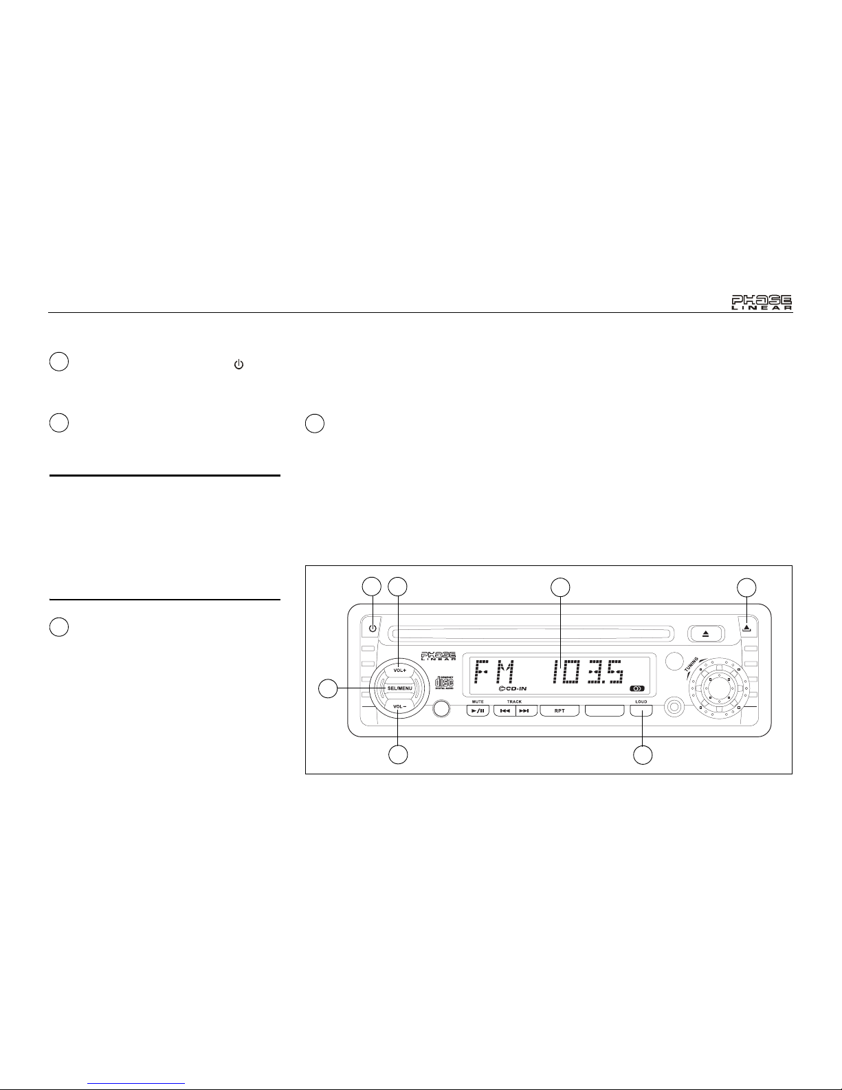
To adjust the bass level, press the SEL/MENU
button (4) until “BAS” appears on the display
panel. Within five seconds, press the volume +/
–buttons (3a and 3b) to adjust the bass from
“BAS -5” to “BAS +5”. “BAS 00” represents a
flat response.
Treble Control
To adjust the treble level, press the SEL/MENU
button (4) until “TRE” appears on the display
panel. Within five seconds, press the volume +/
–buttons (3a and 3b) to adjust the treble from a
minimum of “TRE -5” to a maximum of “TRE
+5”. “TRE 00” represents a flat response.
Left/Right Balance Control
To adjust the left-right speaker balance, press
the SEL/MENU button (4) until the “BAL”
indication appears on the display panel. Within
five seconds, press the volume +/– buttons (3a
and 3b) adjust the balance between the left and
right speakers from “BAL 12L” (full left) to “BAL
12R” (full right). “BAL L=R” represents an equal
balance level between the left and right
speakers.
Front/Rear Fader Control
To adjust the front/rear speaker balance, press
the SEL/MENU button (4) until “FAD“ appears
on the display panel. Within five seconds, press
the volume +/– buttons (3a and 3b) to adjust
the balance between the front and rear
speakers from “FAD 12F” (full front) to “FAD
12R” (full rear). “FAD F=R” represents an equal
balance level between the front and rear
speakers.
System Menu
Press and hold the SEL/MENU button (4) to
view the system menu. Continue pressing the
SEL/MENU button to access the menu options
in the following order: BEEP ON/OFF, P--VOL
(turn-on volume), CLK ON/OFF, Display
Priority, 12/24 HOUR clock setting. Use the
volume +/– buttons (3a and 3b) to adjust menu
option settings.
• Audible BEEP (ON/OFF): Select ON to
hear an audible beep each time a function
is activated.
• P--VOL (00-46): Select the desired default
turn-on volume.
• CLK (ON/OFF): Select ON to have the
clock appear on the LCD when the radio is
turned off. Choose OFF to have the LCD
remain dark when the radio is turned off.
• Display Priority (FREQ PRI, CLK PRI, NO
PRI): Select FREQ PRI to revert to the
frequency display after a few seconds of
inactivity. Select CLK PRI to automatically
revert to the clock display after a few
seconds of inactivity. Select NO PRI if you
do not want the display to automatically
change. Use the DISP button to change
your display preference.
• (12/24) HOUR: Select 12 or 24 hour
display mode for the clock.
Loudness Control (BAND/
LOUD)
When listening to music at low volumes, this
feature will boost the bass and treble ranges to
compensate for the characteristics of human
hearing. Press and hold the BAND/LOUD
button (5) to activate this feature as indicated
by “LOUD ON” or “LOUD OFF” on the display
panel. With the LOUD status displayed, press
the BAND/LOUD button again to switch
between ON and OFF.
AM/FM Band Selector
During radio play, press the BAND button (5) to
change the radio band. The indications “AM” or
“FM” appear on the display panel according to
your selection.
4
4
4
4
45
5

PCD161A
9
OPERATING INSTRUCTIONS
Manual Tuning Control
Turn the manual TUNING control (6) clockwise
to tune upward in frequency on the band in use
or counter-clockwise to tune downward in
frequency. The frequency to which you are
tuned will be shown in digital format on the
display panel. When tuning in a station, always
adjust the control so that the correct broadcast
frequency is shown on the display and you are
receiving a clear signal. If the radio is tuned off-
frequency, you could experience distorted
audio, noise and other reception problems.
Source Button (MODE)
The MODE button (7) enables selection of
radio, disc or auxiliary device playback. When a
CD is playing, press the MODE button to revert
to radio operation.
Auxiliary Input
To access an auxiliary device:
1. Connect the portable audio player to the
AUX IN interface on the front panel (8).
2. Press the MODE button (7) to select Aux In
mode.
3. Press MODE again to cancel Aux In mode
and go to the next mode.
Audio Mute
Press the MUTE ( ) button (9) to mute the
radio volume from the system. “MUTE” will
appear on the display panel and the volume will
be muted. (If you press this button while a CD is
playing, CD play will be paused.) Press MUTE
again, or press the volume +/– buttons (3a and
3b) or the SEL/MENU button (4) to return the
volume level to the setting in use before the
mute function was activated.
6
7
8
9
T
U
N
I
N
G
DISP
AUX IN
SCN
MODE
PCD161A
BAND
2
1
3b
3a
4
567 8
9

PCD161A
10
OPERATING INSTRUCTIONS
Display Selector (DISP)
This unit can display either the clock time or
radio frequency/CD player functions.
Depending on your System Menu settings (see
“System Menu”), the radio frequency, CD player
track indication or clock may be displayed.
Press the DISP button (10) to change between
Frequency/CD information and clock display.
Setting the Clock
To set the clock, perform the following steps:
1. Turn the vehicle ignition and radio on.
2. Press and hold the DISP button (10) until the
time display flashes.
3. Within 5 seconds, press the volume + button
(3a) to adjust the hour.
4. Press the volume – button (3b) to adjust the
minutes.
Five seconds after the last hour or minute
adjustment has been made, the time will set
and normal operation will resume.
10

PCD161A
11
T
U
N
I
N
G
DISP
AUX IN
SCN
MODE
PCD161A
BAND
CD PLAYER OPERATING INSTRUCTIONS
Disc Slot
With the label surface facing up, fully insert a
compact disc into the slot (11) until the
mechanism engages and pulls the disc in. The
disc symbol ( )and “S -- CDP” will appear on
the display. Play will begin from the first track
on the disc and the track number and elapsed
time of track play will appear on the display.
NOTE: The unit is designed for play of
standard 5” (12 cm.) compact discs only. Do
not attempt to use 3” (8 cm.) CD singles in
this unit, either with or without an adaptor,
as damage to the player and/or the disc may
occur. Such damage will not be covered by
the warranty on this product.
CD Play/Pause Selector
During disc play, press the (play/pause)
button (9) to pause the disc. When paused, “S -
- PAUSE” appears on the display, the disc
symbol flashes, and play is suspended. When
pressed again, playback resumes from the
point at which disc play was stopped.
Forward Track Selector
During disc play, the forward TRACK | button
(12) is used to quickly select the beginning of a
particular track in the forward direction. With
each press of the button, the next higher track
number will be selected as shown on the
display panel.
Backward Track Selector
During disc play, the backward TRACK |
button (13) is used to quickly select the
beginning of a particular track in the backward
direction. With each press of the button, the
next lower track number will be selected as
shown on the display panel.
, Cue/Review Functions
High-speed audible search to any section of the
disc can be made by the Cue and Review
functions. Press and hold the forward TRACK
| button (12) to advance rapidly in the forward
direction or the backward TRACK | button
(13) to advance rapidly in the backward
direction.
11
9
12
13
12 13
11
5
4
3a
3b 9
6
1
12
13
16
15
14
17

PCD161A
12
CD PLAYER OPERATING INSTRUCTIONS
Repeat Play Selector (RPT)
During disc play, press the RPT button (14) to
repeat the playback of a desired track
(“S -- RPT” appears on the display panel,
followed by the current track number). Play of
the selected track will continue to repeat until
the Track Repeat function is cancelled by
pressing the RPT button again or by activating
the Scan function, causing the “S -- RPT”
indication to disappear.
Track Scan Select (SCN)
During disc play, press the SCN button (15) to
play the first 10 seconds of each track. (“S --
SCN” is displayed with the track number).
When a desired track is reached, press the
SCN button again to cancel the function and
play the selected track. Track Scan mode can
also be canceled by activating the Repeat Play
(14) function.
Disc Eject Button
Press the eject button (16) to stop disc play
and eject the disc. The unit will revert to radio
operation. Discs may be ejected with the
vehicle ignition switch on or off. If an ejected
disc is not removed from the disc slot within 10
seconds of being ejected, the disc will be re-
inserted automatically, and the disc symbol will
reappear on the display to show that a disc is
still installed in the unit.
NOTE: To prevent a disc from accidentally
being damaged, always remove the disc
from the unit when disc play is finished.
14
15
16

PCD161A
13
CARE AND MAINTENANCE
Your new radio/CD player does not require any
maintenance. However, proper understanding
of its use and handling will help you obtain
maximum enjoyment of its capabilities. We
recommend that you keep this manual for
reference on the many features of this unit as
well as how to set the clock. The following
points should be observed:
• When cleaning the interior of the vehicle, do
not get water or cleaning fluids on the unit.
• The CD player is a precision instrument and
will not operate properly in extreme heat or
cold. If such conditions occur, wait until the
interior of the vehicle reaches a normal
temperature before using the player.
• If the temperature inside the player gets too
hot, a protective circuit will automatically
stop play of the disc. In this case, allow the
unit to cool before operating the player
again.
• Never insert anything other than a 5" (12
cm) compact disc into the player as the
mechanism can be damaged by foreign
objects.
• Do not attempt to use 3" (8 cm) CD-Single
discs in this unit, either with or without an
adaptor, as damage to the player and/or disc
may occur. Such damage will not be covered
by the Warranty on this product.
• When not using the disc player, always
remove the compact disc. Do not leave an
ejected disc sitting in the disc slot as this can
expose it to sunlight and other causes of
damage.
• Do not attempt to open the unit chassis.
There are no user-serviceable parts or
adjustment points inside.
• When the vehicle warms up during cold
weather or under damp conditions,
condensation may appear on the lens of the
disc player. Should this occur, the player will
not operate properly until the moisture has
evaporated.
• The unit is designed with a vibration
dampening CD mechanism to minimize
interruption of disc play due to normal
vibration. When driving on rough roads,
however, occasional sound skips may occur.
This will not scratch or damage the disc and
normal play will resume when the rough
conditions cease.
Handling Compact Discs
Dirt, dust, scratches and warping can cause
skips in the playback and deterioration of sound
quality. Please follow these guidelines to take
care of your compact discs:
• Carefully wipe fingerprints, dust and dirt from
the disc’s playing surface with a soft cloth.
Wipe in a straight motion from the center to
the outside of the disc.
• Never use chemicals such as record sprays
or household cleaners to clean CDs, as they
can irreparably damage the disc’s surface.
• Discs should be kept in their storage cases
when not in use.
• Do not expose discs to direct sunlight, high
temperatures or high humidity for long
periods.
• Do not stick paper, tape or labels on disc
surfaces.
RESET BUTTON
A Reset button is located behind the
faceplate on the left side (the front panel
must be removed to access the button). The
Reset function should only be activated
under the following circumstances as it will
erase the time and pre-set memories: Upon
initial installation after all wiring is
completed; If there is a malfunction of any
of the switches on the unit, pressing the
Reset button may clear the system and
return to normal operation.

PCD161A
14
SPECIFICATIONS
CD-R and CD-RW Capability
Depending on media type and method of
"recording/burning", some CD-R/RWs may be
incompatible with this unit. After "recording/
burning", the session must be closed. Please
refer to your software's recommended
procedures for closing a disc/session. Review
your recording software to familiarize yourself
with the correct "recording/burning" procedures.
We recommend using the latest versions of
ROXIOTM or NEROTM burning software.
This unit will only recognize the CDDA/CDC
formats "recorded / burned" onto a CD-R/RW.
This unit does not support .WAV, .WMA, .MP3,
.OGG or other formats.
Technical Specifications
CEA Power Ratings
Power Output: 13 watts RMS X 4 channels into
4-ohms @ < 1% THD+N
Signal to Noise Ratio: 70dBA below reference.
(Reference: 1 watt, 4-ohms)
Frequency Response: 20Hz to 20kHz, -3dB
Reference Supply Voltage: 14.4VDC
CD Player
Signal to Noise Ratio: >85dBA
Frequency Response: 20Hz to 20kHz, -3dB
Channel Separation: > 55dB @ 1kHz
D/A converter: 1Bit/Ch
FM Tuner
Tuning Range: 87.5MHz - 107.9MHz
Mono Sensitivity: 18dBf
50dB Stereo Quieting Sensitivity: 20dBf
Stereo Separation @ 1kHz: >30dB
Frequency Response: 30Hz to 12kHz, -3dB
AM Tuner
Tuning Range: 530kHz - 1710kHz
Sensitivity @ 20dB: 30uV
Signal to Noise Ratio: @1 kHz >50dB
Frequency Response: 50Hz - 2kHz, -3dB
General
Power Supply: 11 to 16VDC, negative ground
Fuses: Battery - 15 amp / AGC, Ignition / 0.5
amp / AGC, Accessory
Dimensions: 7" X 7" X 2" (178mm x 178mm x
51mm)
Specifications subject to change without
notice.

PCD161A
Manual del Usario

PCD161A
16
PREPARACIÓN
Comenzando
Es buena idea leer completamente las
instrucciones antes de iniciar la instalación.
Contenido
Instrucciones de Instalación.................... 17
Cableado................................................. 19
Instalación de la Cubierta Desmontable.. 20
Instrucciones de Operación..................... 21
Funcionamiento del Lector de CD........... 25
Cuidados y Mantenimiento...................... 27
Especificaciones...................................... 28
Requisitos para la Instalación
Esta unidad está diseñada para instalarse en
autos, camiones y camionetas con abertura
para radio preexistente. En muchos casos, se
necesitará un equipo de instalación especial
para montar el radio al tablero de instrumentos.
Estos equipos se consiguen en tiendas de
artículos electrónicos o tiendas de estéreos
para automóviles. Antes de comprar el equipo,
asegúrese de que funcione con su vehículo. Si
necesita un equipo de instalación pero no
puede conseguirlo, llame a nuestra línea de
atención al cliente al 1-800-645-4994 (sólo para
U.S.A. y Canadá).
Herramientas y Provisiones
Las siguientes herramientas y provisiones son
necesarias para instalar el radio:
• Llave torx, destornilladores plano y Philips
• Cúter y peladores de cables
• Herramientas para remover la radio
existente (destornillador, equipo de llave
de casquillo y otras herramientas)
• Cinta aisladora
• Enganchador
• Voltímetro / luz de prueba
• Conexiones para enganchar
• Cable de calibre 18 para conexiones
eléctricas, cable de altoparlante de calibre
16 a 18
Requerimientos del Altavoz
Solamente conecte los altavoces de carga de
impudencia de 4 ohms. Altavoces con una
carga de impedancia menor a los 4 ohms
pueden dañar la unidad.
Desconecte la Batería
Antes de empezar, siempre desconecte la
terminal negativa de la batería.
Asistencia Gratuita en la
Instalación
Si requiere asistencia, llame al Soporte Técnico
al 1-800-323-4815 de lunes a viernes de 8:30
AM a 7:30 PM tiempo del este y los sábados de
9:00 AM a 5:00 PM tiempo del este (para USA
y Canadá solamente.
Pour des instructions en Francais, référez-vous à la page 30.
For instructions in English, refer to page 2.

PCD161A
17
INSTRUCCIONES DE INSTALACIÓN
Instalación Utilizando una Manga
de Montaje
1. Deslice la manga de montaje fuera del
chasis. Si está trabada, utilice la herramienta
para quitarla (provista).
2. Verifique el tamaño de apertura del tablero
deslizando la manga de montaje adentro del
mismo. Si la apertura no es lo
suficientemente grande, cuidadosamente
córtela o límela hasta que la manga se
deslice hacia adentro sin dificultad. No fuerce
la manga al introducirla en la apertura ni
provoque que se doble. Verifique si hay
suficiente espacio detrás del tablero para el
chasis del radio.
3. Localice la serie de lengüetas para doblar en
la parte superior, inferior y costados de la
manga de montaje. Con la manga
completamente insertada en la apertura del
tablero, doble hacia afuera todas las
lengüetas que sean necesarias para que
quede sujeta firmemente al tablero.
4. Ubique el radio en frente de la apertura del
tablero de manera tal que los cables puedan
pasar por la manga de montaje. Siga el
diagrama de cableado detalladamente y
asegúrese de que todas las conexiones
estén seguras y aisladas con tuercas para
cables y cinta aisladora para asegurar el
apropiado funcionamiento de la unidad.
Luego de completar las conexiones del
cableado, encienda la unidad para confirmar
la operación (la ignición del vehículo debe
estar encendida). Si la unidad no opera,
verifique nuevamente todas las conexiones
de cables hasta que se solucione el
problema.
5. Asegúrese de que el radio tenga el lado
correspondiente hacia arriba, luego
cuidadosamente deslícelo dentro de la
manga de montar hasta que esté
completamente asentado y las presillas lo
traben en su lugar.
6. Fije un extremo de la cinta de soporte
perforada (provista) al perno en la parte
trasera del chasis utilizando la tuerca
hexagonal suministrada. Asegure el otro
extremo de la cinta perforada a una parte
firme del tablero, ya sea arriba o abajo del
radio, utilizando el tornillo provisto. Doble la
cinta hasta colocarla en la posición
adecuada.
7. Verifique la operación del radio leyendo
las Instrucciones de Operación.
T
U
N
I
N
G
DISP
AUXIN
SCN
MODE
PCD161A
BAND
CUIDADO: La cinta de soporte se
debe utilizar para prevenir daños
al tablero debido al peso del radio
o una inadecuada operación
causada por vibraciones.
CUIDADO: Para una correcta
operación del equipo de CD, el
chasis debe estar montado dentro
de los 20° de horizontalidad.
Asegúrese de que la unidad esté
montada dentro de este límite.
DOBLE LAS ALETAS
INSTALACIÓN

PCD161A
18
INSTRUCCIONES DE INSTALACIÓN
Equipo de Instalación
Si su vehículo requiere el uso de un equipo de
instalación par amontar este radio, siga las
instrucciones incluidas con el equipo de
instalación para adherir el radio al plato de
montaje provisto en el equipo.
1. Conecte el cable y verifique el radio como
se determina en las instrucciones de Insta-
lación Universal.
2. Instale el radio o el ensamblaje del plato de
montaje al segundo tablero, de acuerdo a
las instrucciones en el equipo de instalación.
3. Adjunte la cinta de soporte al radio y al
tablero como se describe en las instruc-
ciones de Instalación Universal.
4. Reemplace el panel de ajuste del tablero.
Instalación ISO
Esta unidad tiene agujeros roscados en los
paneles laterales de chasis que pueden
utilizarse con las ménsulas de montar
originales de fábrica que vienen con algunos
vehículos para motar el radio al tablero. Por
favor, consulte en su tienda local de estéreos
de automóviles si necesita asistencia en este
tipo de instalación.
1. Quite del tablero el radio existente de fábrica
o centre la consola de montaje. Guarde
todos los elementos y ménsulas pues serán
utilizados para montar el nuevo radio.
2. Con cuidado destrabe el marco plástico del
frente del chasis del nuevo radio. Quite y
deseche el marco.
3. Quite las ménsulas y elementos de montaje
que vienen de fábrica con el radio existente
y adhiéralos al nuevo radio.
NOTA: No exceda el tamaño de tornillo de M5 x
9MM. Tornillos más largos pueden tocar y dañar
componentes dentro del chasis.
4. Conecte los cables del nuevo radio al
vehículo como se especifica en las instruc-
ciones de Instalación Universal.
5. Monte el ensamblaje del nuevo radio al tablero
o a la consola central utilizando el
procedimiento reverso al paso 1.
Quitando el Radio
Para quitar el radio luego de la instalación:
1. Inserte los dedos en la ranura en la parte
delantera del marco y jálelo hasta quitarlo
completamente. (Cuando fije nuevamente el
marco, apunte el lado con ranura hacia
abajo y reajuste).
2. Inserte las llaves para quitar nuevamente
hasta que hagan clic, luego jale el radio
hacia fuera. Si las llaves para quitar están
insertadas en un ángulo, no se fijarán adec-
uadamente para liberar la unidad.
Ranura
Llaves
Manga de Montaje
Llaves
CÓMO DESMONTAR EL RADIO
INSTALACIÓN ISO

PCD161A
19
Gris
+
LF/AVG RF/AVD
LR/ARG RR/ARD
15A
0.5A
Conexión del Amplificador
Conecte la línea de salida para
una amplificación externa
óptima. El conector rojo es para
la derecha y el blanco para la
izquierda.
Alimentación Antena
Conectar a la antena o al
amplificador. Si no se utilizara
el cable, se debe recubrir la
punta del cable.
Conexión a Tierra
Conectar a la terminal de tierra.
Memoria/Batería
Conectar a la bateríaoala
fuente de energía de 12 voltios
que está siempre viva. La radio
no funcionará si este cable no
está conectado.
Accesorio/Ignici nó
Conectar al cable de la radio
o al fusible de la radio.
Fusibles
Cuando reemplace un fusible
asegoerese que el fusible nuevo
sea del tipo correcto y tenga el
amperaje adecuado. Si utiliza
un fusible incorrecto.
Blanco/Negro (-)
Blanco (+)
Gris/Negro (-)
Gris (+)
Violeta (+)
Verde (+)
Verde/Negro (-) Violeta/Negro (-)
Azul
Negro
Amarillo
Rojo
Conector para la Antena
CABLEADO
¡CUIDADO! Nunca combine (hacer puente)
las salidas para utilizar sólo 1 altavoz.
¡CUIDADO! Nunca tome a tierra las puntas
negativas del altavoz utilizando el piso del
chasis.
CUIDADO: El no colocar los cables
exactamente como se muestra puede
causar daños eléctricos al radio.

PCD161A
20
INSTALACIÓN DE LA CUBIERTA DESMONTABLE
Instalación de la Cubierta
Para instalar la cubierta:
1. Deslice el lado izquierdo del panel delantero
hacia adentro del radio.
2. Suavemente presione el lado derecho en su
lugar.
Desprendimiento de la Cubierta
Para quitar la cubierta:
1. Presione el botón para liberar (17).
2. Jale suavemente del lado derecho del panel
delantero para quitarlo.
3. Por seguridad, mantenga el panel delantero
en la caja de protección suministrada.
Precauciones al Manipular
• Asegúrese de que el panel delantero tenga el
lado correspondiente hacia arriba cuando lo
adhiera al chasis, dado que no puede ser
adherido si está al revés.
• No presione con fuerza el panel delantero
cuando lo adhiera al chasis. No es necesaria
más que una presión moderada.
• Cuando adhiera el panel delantero,
asegúrese que esté centrado en el marco del
chasis y que lo está presionando justo en su
lugar.
• No deje caer el panel delantero.
• No presione la pantalla o los botones de
control cuando manipule el panel delantero.
• No toque los contactos del panel delantero o
de la unidad principal.
• Quite la suciedad o substancias externas
solamente con una tela limpia y seca.
• No exponga el panel delantero a
temperaturas extremas o al sol.
• Mantenga agentes volátiles tales como
bencina, solvente o insecticidas lejos del
panel delantero.
• No desarme el panel delantero.
• Cuando lleve el panel delantero con usted,
por favor utilice la caja suministrada para
protegerlo de daños o suciedades.
•Asegúrese de que no haya polvo o suciedad
en las terminales eléctricas de la parte
trasera del panel, pues esto puede causar
operación intermitente u otro tipo de mal
funcionamiento.
STEP 1
STEP 2
>30%
d
>30%
d
PUSH
STEP 1 STEP 2
Table of contents
Languages:
Other Phase Linear Car Stereo System manuals
Popular Car Stereo System manuals by other brands

LG
LG LCS327UB1 owner's manual

Alpine
Alpine CDA-9853R owner's manual

Rockford Fosgate
Rockford Fosgate RFX9020M Installation & operating guide

JL Audio
JL Audio Stealthbox SB-F-TRKCTR/10W3 installation guide

Alpine
Alpine IVA-C800E owner's manual

Metra Electronics
Metra Electronics Car Stereo System installation instructions