Phase Technologies DV Series User manual


ii | Page
2022 © Copyright.V0.0 All rights reserved. All contents are property of Phase Technologies, LLC.
No portion of this publication or its contents may be duplicated by any means, electronic or otherwise, without the
express written consent of Phase Technologies, LLC.
V0.0_09012022
222 Disk Drive
Rapid City, SD 57701
Phone: 605-343-7934
Fax: 605-343-7943
Toll Free: 866-250-7934
www.phasetechnologies.com

iii | Page
SAFETY MESSAGES AND WARNINGS
To ensure safe and reliable operation of output filters, it is important to carefully read
this manual and to observe all warning labels attached to the unit before installing.
Please follow all instructions exactly and keep this manual with the unit for quick and
easy reference.
Definitions of Warning Signs and Symbols
CAUTION: Indicates a potentially hazardous situation that could result in injury or
damage to the product.
WARNING: Indicates a potentially hazardous situation that could result in serious
injury or death.
HIGH VOLTAGE: The voltage associated with the procedures referenced could
result in serious injury or death. Use caution and follow instructions carefully.
READ THESE WARNINGS BEFORE INSTALLING
OR OPERATING EQUIPMENT!
WARNING: Risk of electric shock. More than one disconnect switch may be
required to de-energize the equipment before servicing.
WARNING: Risk of electric shock. Before servicing the equipment, de-energize
the filter by disconnecting all incoming sources of power, wait 10 minutes for internal
charges to dissipate, and verify with a voltmeter that all power sources are off and
capacitors are discharged. Failure to do so may result in severe injury or death.
HIGH VOLTAGE: This equipment is connected to line voltages that can create a
potentially hazardous situation. Electric shock could result in serious injury or death.
This device should be installed only by trained, licensed, and qualified personnel. Follow
instructions carefully and observe all warnings.
WARNING: This equipment should be installed and serviced by qualified personnel
familiar with the type of equipment and experienced in working with dangerous voltages.
WARNING: Installation of this equipment must comply with the National Electrical
Code (NEC) and all applicable local codes. Failure to observe and comply with these
codes could result in risk of electric shock, fire, or damage to the equipment.
CAUTION: Circuit breakers, fuses, proper ground circuits, and other safety
equipment and their proper installation are not provided by Phase Technologies, LLC,
and are the responsibility of the end user.

iv | Page
CAUTION: Failure to maintain adequate clearance may lead to overheating of the
unit and cause damage or fire.
WARNING: Input power connections should be made by a qualified electrician into
circuit with adequate voltage and current carrying capacity for the model.
CAUTION: Use 600 V vinyl-sheathed wire or equivalent. The voltage drop of the
leads needs to be considered in determining wire size. Voltage drop is dependent on
wire length and gauge. Use only copper conductors.
CAUTION: Wires fastened to the terminal blocks shall be secured by tightening
the terminal screws to a torque value listed in Table 4.
CAUTION: The maximum wire gauge for the input terminals is listed in Table 4.
CAUTION: Never allow bare wire to contact metal surfaces.
CAUTION: For SW filters with internally powered fans, ensure that the variable
frequency drive (VFD) is set to V/f (Volts per Hz) mode. Failure to properly configure
the VFD could result in failure of the VFD or filter components.
CAUTION: Before installation, visually inspect the filter and secure any loose
electrical connections before applying power. Failure to do so may result in damage to
the filter or diminished performance.

v | Page
TABLE OF CONTENTS
INTRODUCTION..................................................................................................... 1
1.1 RECEIVING INSTRUCTIONS .................................................................................. 2
1.2 MODELS AND RATINGS ....................................................................................... 3
RATINGS ................................................................................................................ 5
2.1 PRODUCT SPECIFICATIONS ................................................................................. 5
INSTALLATION...................................................................................................... 7
3.1 MOUNTING YOUR NEW [PRODUCT NAME] FILTER ............................................. 7
3.2 PROPER VENTILATION ........................................................................................ 7
3.3 GROUNDING ...................................................................................................... 7
3.4 WIRE SIZING...................................................................................................... 7
3.5 CONNECTING THE LOAD..................................... ERROR!BOOKMARK NOT DEFINED.
3.6 CONNECTING TO FIELD WIRING TERMINALS ........ ERROR!BOOKMARK NOT DEFINED.
OPERATION.................................................ERROR! BOOKMARK NOT DEFINED.
4.1 COMMISSIONING THE UNIT ................................. ERROR!BOOKMARK NOT DEFINED.
TROUBLESHOOTING ...........................................................................................10
ENCLOSURE DIMENSIONS ........................ERROR! BOOKMARK NOT DEFINED.
WARRANTY ..........................................................................................................13

1 | Page
INTRODUCTION
Output filters are used to remove unwanted high frequency content from the output of a
Variable Frequency Drive (VFD). Large voltage spikes are produced when VFDs are used to
drive motors with long cable leads, which can damage motor or cable insulation systems or
motor bearing fluting due to electric discharge. This voltage spike is known as the Reflected
Wave Phenomenon. dV/dt filters extend motor and cable life by reducing the effects of the
Reflected Wave Phenomenon and removing high frequency voltage spikes. dV/dt filters
should be used when motor cables exceed 50 feet and sine wave filters should be used when
motor cables exceed 900 feet.
For additional protection, sine wave filters provide more robust removal of higher frequency
content. As well as providing protection against voltage spikes from reflected waves, a sine
wave filter additional removes lower order harmonic voltage and currents. These benefits are
realized in reduced motor losses (less heating) due to lower eddy currents and magnetic
hysteresis losses in motor steel laminations.
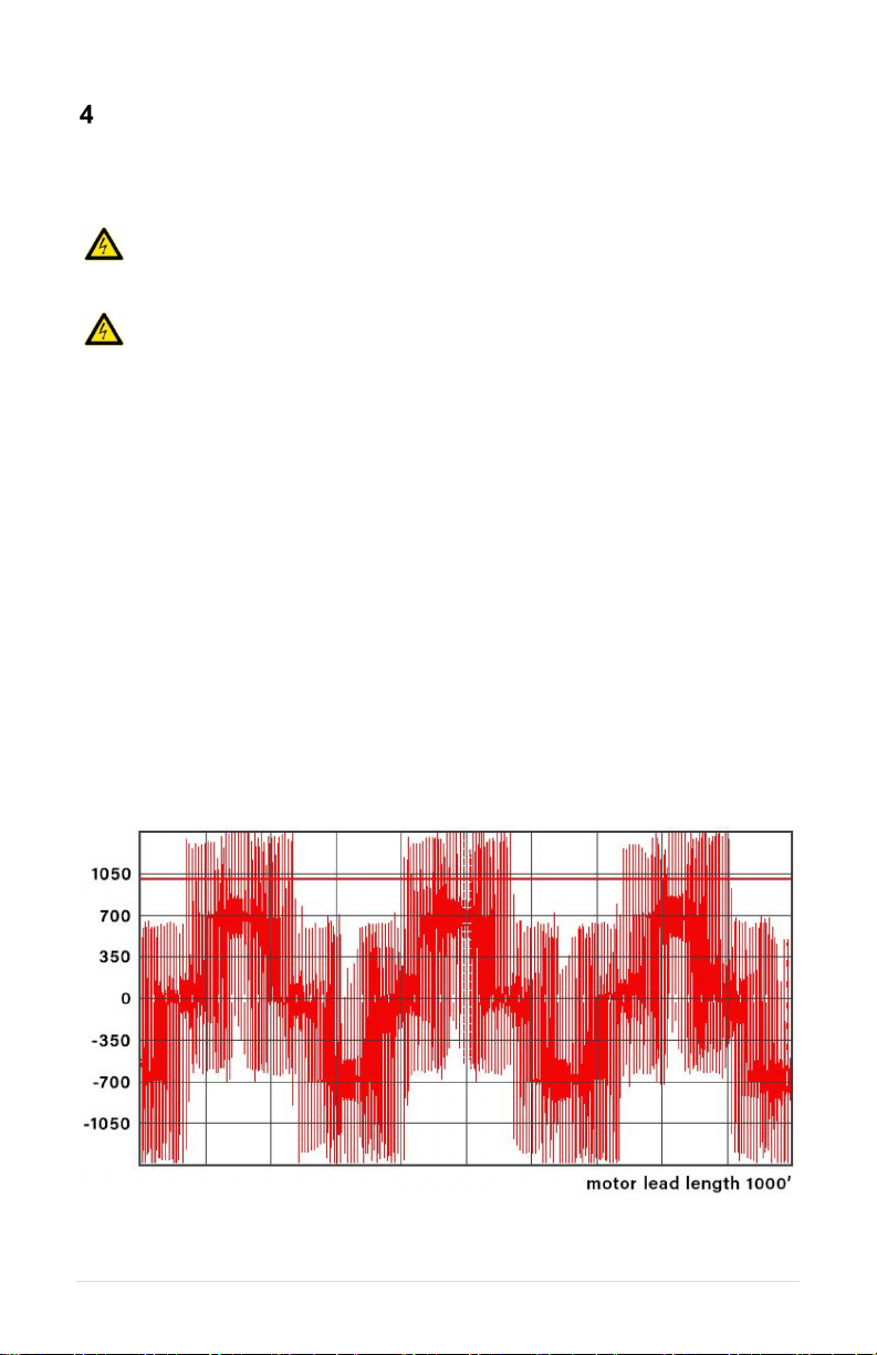
Figure 1shows an unfiltered VFD output voltage measured line-to-line.
Figure 1– Unfiltered VFD Output Voltage

2 | Page
Figure 2shows output voltage after being filter by the dv series dV/dt filter.
Figure 2– Output Voltage After dv Series dV/dt filter.
Figure 3shows a output voltage after being filtered by the sw series sine wave filter.
Figure 3– Output Voltage After sw Series Sine Wave Filter.
Phase Technologies output filters can be configured in Open, NEMA Type 1, or NEMA Type
3R enclosures. Open filters are intended to be installed in a panel. Type 1 filters come with
an enclosure designed for indoor use only. Type 3R enclosures are made for outdoor use.
Make sure the filter has the proper enclosure type for your application.
1.1 Receiving Instructions
Phase Technologies sine wave filters are thoroughly inspected and tested before packaging
for shipment. Upon receiving the unit, immediately inspect it for any damage that may have
occurred during shipping. If any damage is found, contact the Phase Technologies’ service

3 | Page
department at (605) 343-7934. Loose electrical connections can also cause damage to the
filter or diminish its performance. Visually inspect the filter and tighten any loose connections
found.
1.2 Nomenclature
1.3 Models and Ratings
Table 1– dV/dt Filter Ratings
Model
HP
Rated Current (A)
DV009E
5
9
DV013E
7.5
13
DV018E
10
18
DV031E
20
31
DV045E
30
45
DV060E
40
60
DV077E
50
77
DV090E
60
90
DV107E
75
107
DV128E
100
128
DV160E
125
160
DV200E
150
200
DV250E
200
250
DV362E
300
362
DV480E
400
480
Table 2– Sine Wave Filter Ratings
Model
HP
Rated Current (A)
SW009E
5
9
SW013E
7.5
13

4 | Page
SW018E
10
18
SW031E
20
31
SW045E
30
45
SW060E
40
60
SW077E
50
77
SW090E
60
90
SW107E
75
107
SW128E
100
128
SW160E
125
160
SW200E
150
200
SW250E
200
250
SW362E
300
362
SW480E
400
480
5 | Page
RATINGS
2.1 Product Specifications
Table 3 –General Specifications, dv Series Filters
dV/dt Filter
Input Voltage Waveform PWM
VFD Output Voltage ≤ 480 VAC, 3-phase
VFD Output Frequency ≤ 90 Hz
VFD Switching Frequency 2 kHz – 10 kHz
Current Range 9 – 480 A
Maximum Motor Lead Length 1,000 feet
Max Peak Voltage
150% of DC bus voltage
up to 1,000 feet
Max dV/dt at Motor ≤200V/µs
Insertion Loss (Voltage)
≤1% at 60Hz
≤1.5% at 90Hz
Efficiency ≥ 99%
Enclosure Options
Open, NEMA 1, or
NEMA 3R
Operating Temperature
-20 °C to 40 °C
(-4 °F to 104 °F)
Storage Temperature
-25 °C – 74 °C
(-13 °F – 165 °F)
Maximum Humidity 95%, non-condensing
Elevation
Derate by 5 °C for every
2,000 feet over 5,500 feet
of elevation

6 | Page
Table 4 –General Specifications, SW Series Filters
SW Sine Wave Filter
Input Voltage Waveform PWM
VFD Output Mode Volts per Hertz*
VFD Output Voltage ≤ 480 VAC, 3-phase
VFD Output Frequency ≤ 90 Hz
VFD Switching Frequency 2 kHz – 10 kHz
Current Range 9 – 480 A
Insertion Loss (Voltage)
≤ 3.8% at 60 Hz
≤ 5.7% at 90 Hz
Efficiency ≥ 98%
Enclosure Options
Open, NEMA 1, or
NEMA 3R
Operating Temperature
-20 °C to 40 °C
(-4 °F to 104 °F)
Storage Temperature
-25 °C – 74 °C
(-13 °F – 165 °F)
Maximum Humidity 95%, non-condensing
Elevation
Derate by 5 °C for every
2,000 feet over 5,500 feet
of elevation
*SW200, SW250, SW362, SW480 models

7 | Page
INSTALLATION
3.1 Mounting Your New Output Filter
Proper installation of the unit is important to the performance and normal operating life. It
should be installed in a location free from:
•Corrosive gases or liquids
•Excessive vibration
•Airborne metallic particles
Open type filters should be installed in a panel by a qualified UL 508A panel shop. If wall-
mounted, mount the unit to a solid, non-flammable surface capable of bearing the weight
using the mounting brackets provided with the unit. Floor mounted filters should be attached
to the legs provided and fastened to the floor using concrete anchors or similar hardware.
3.2 Proper Ventilation
To maintain air circulation for adequate cooling, minimum clearance around the unit must be
maintained. Allow six inches on each side and top, and 18 inches below.
Ensure openings are not obstructed. If the unit is mounted in a small room, cabinet, or
building, ensure there is adequate ventilation to provide sufficient cooling for the unit.
3.3 Grounding
•Properly ground the filter according to local electrical code.
•Connect the ground lug to the branch circuit or service ground conductor.
•Resistance to ground measurement must be 25 Ohms or less, according to the
National Electric Code.
3.4 Ground Fault Protection
Devices that utilize power switching electronics like variable frequency drives, emit high
leakage current so ground fault protection devices may not be compatible with a VFD and
output filter.
3.5 Overtemperature Switch
Phase Technologies output filters have an optional self-resetting overtemperature circuit with
a Normally Closed relay that will open when an internal temperature of 180°C is reached (+/-
5°C). An overtemperature relay is highly recommended to shut down the VFD if the internal
temperature reaches an unsafe level to prevent damage to the filter in rare cases when
components overheat due to abnormal operating conditions. If using a Phase Technologies
VFD, the overtemperature relay should be connected to one of the Auxiliary terminals and
the setting AUX SELECT should be set to CLOSED = RUN, OPEN = STOP.
Table 4– Overtemperature Switch
Normally Closed (NC) Thermal Switch:
180°C open, +/-5°C
Voltage Current
250VAC 8A

8 | Page
3.6 Installing Power Wiring
WARNING: Input and output wiring to the filter should be performed by authorized
personnel in accordance with the NEC and all local electrical codes and regulations.
CAUTION: Use 600 V wire that is appropriately rated for the current rating of the motor.
Use copper wire with an insulation temperature rating of 90°C or higher. Installations must
comply with all local regulations and the National Electrical Code (NEC).
Verify that the power source is appropriate for the filter being used. Connect the VFD output
(T1, T2, T3 or U, V, W) to the input of the filter (U1, V1, W1). Connect the motor to the output
terminals of the filter (U2, V2, W2). A fused disconnect or circuit breaker should be installed
between the VFD and its power source in accordance with NEC requirements. See Figure
for a system schematic and Table 2 for field wiring terminal specifications.
Figure 4– Filter System Schematic
Table 5 – Field Wiring Power Terminal Specifications
3.7 Startup Checklist
Prior to operation, verify the following:
1. The filter is securely attached to the proper mounting surface
2. All filter ground terminals are properly bonded to earth ground
3. The filter’s input terminals are connected to the output of a VFD and the VFD is
set properly*:
oOutput frequency is less than 90 Hz
oPWM Switching Frequency is 2 – 8 kHz
oOperation mode is Volts per Hertz without DC braking
4. An appropriately rated motor is connected to the output terminals
5. The motor is secured and properly mounted

9 | Page
*Consult Phase Technologies about derate information if desired to operate outside of
these VFD settings.
Note: VFD motor auto-tuning procedures will be greatly affected and likely will result in
inaccurate results. Consult with VFD supplier if auto-tuning is desired with filter installed.
10 | Page
TROUBLESHOOTING
This section provides information on routine inspections and troubleshooting tips for potential
system problems.
WARNING: Risk of electric shock. De-energize the unit by disconnecting all incoming
sources of power, then wait 5 minutes for internal charges to dissipate before servicing
the equipment.
HIGH VOLTAGE: This equipment is connected to line voltages that can create a
potentially hazardous situation. Electric shock could result in serious injury or death.
This device should be installed and serviced only by trained, licensed and qualified
personnel. Follow instructions carefully and observe all warnings.
4.1 Routine Inspection and Maintenance
The unit should be inspected and cleaned at least annually or more frequently if it is in an
excessively warm or dusty environment. Annual inspections should include the following:
•Ensure that the installation environment is free of excessive dirt or contaminants
•Check that all enclosure openings are unobstructed
•Visually inspect the interior of the enclosure for signs of excessive heat or arcing
on components and wires
•Verify that all ground connections are tight
•Retorque VFD and motor connections
4.2 Evaluating Output Filter Performance
Output filter performance can be evaluated by viewing the output voltage wave form with an
oscilloscope. Figure 1shows a typical VFD output voltage waveform when measured line-
to-line.
Figure 5– VFD Line-to-Line Output Voltage Waveform
Figure 2shows a typical filter output voltage as measured line-to-line with an oscilloscope.


12 | Page
Table 5 – Troubleshooting Guide
PROBLEM
POTENTIAL CAUSE
SOLUTION
Motor Will Not
Turn
No power
Check breakers and fuses and verify
incoming voltage.
Incorrect Wiring
Verify VFD and motor are properly
connected to the filter.
VFD Fault
Consult VFD User’s Manual.
VFD Overcurrent
Fault
Incorrect wiring
Verify that all VFD and motor cables are
connected properly.
Cable insulation
compromised
Check wire connections. Use Megger to
check for ground faults.
Motor damage
Check motor winding resistance and use
Megger to check for ground faults.
System compatibility
Verify that current ratings of VFD, output
filter, and motor are properly sized.
VFD parameters
Consult VFD user’s manual to configure
proper parameters.
Temperature
Switch Open
Filter Overheating
Ensure filter openings are clear and that
ambient temperature is below 40 °C.
Incompatible motor
Verify current ratings of VFD, output filter,
and motor are properly sized.
Switching Frequency
is less than 2 kHz
Verify that the VFD Switching Frequency
(or Carrier Frequency) is 2 kHz or higher.
Excessive Filter
Noise
Incompatible motor
Verify current ratings of VFD, output filter,
and motor are properly sized.
Switching Frequency
is less than 2 kHz
Verify that the VFD Switching Frequency
(or Carrier Frequency) is 2 kHz or higher.

13 | Page
WARRANTY
LIMITED WARRANTY
This Limited Warranty applies to the following
Phase Technologies’ product lines:
Output Filters
Two Year Warranty
Output Filters are warranted against defects in material and workmanship. This
warranty covers both parts and labor from the date of purchase from Phase
Technologies. Phase Technologies will repair or replace (at our option), at no
charge, any part(s) found to be faulty during the warranty period specified. The
warranty repairs must be performed by/at a Phase Technologies Authorized Service
Center or at Phase Technologies LLC, Rapid City, SD.
Obligations of Customer
1. The original Bill of Sale must be presented in order to obtain “in-warranty”
service. Transportation to Phase Technologies or an Authorized Service
Center is the responsibility of the purchaser. Return transportation is provided
by Phase Technologies.
2. Installations must comply with all national and local electrical codes.
Exclusions of the Warranty
This warranty does not cover any of the following: accident, misuse, fire, flood, and
other acts of God. Nor does this warranty cover any contingencies beyond the
control of Phase Technologies, LLC, including: water damage, incorrect line voltage,
improper installation, missing or altered serial numbers, and service performed by
an unauthorized facility.
Phase Technologies’ liability for any damages caused in association with the use of
Phase Technologies’ equipment shall be limited to the repair or replacement only of
the Phase Technologies’ equipment. No person, agent, distributor, dealer, or
company is authorized to modify, alter, or change the design of this merchandise
without express written approval of Phase Technologies, LLC.
Installations must comply with all national and local electrical code
requirements.

www.phasetechnologies.com
222 Disk Drive, Rapid City, SD 57701
866-250-7934 - Toll-Free 605-343-7934 - Main
This manual suits for next models
31
Table of contents
Popular Water Filtration System manuals by other brands


GE
GE SmartWater GNSV70FBL Installation information

Sera
Sera Pond fil bioactive user manual

Sunshine Pool Products
Sunshine Pool Products SPE installation instructions

EcoFast
EcoFast EF500-DC Installation and operating instructions

Clarke
Clarke CAT182 Installation & maintenance instructions

Vega
Vega VEGATRENN 149A EX manual