EcoFast EF500-DC User manual

Installaon and Operang Instrucons
EF500‐DC
Direct Connect™ Filter System for
use with kitchen faucet

SAFETY INFORMATION
The EF500‐DC system is designed for use in filtering potable water for in
home use. This is a point of use system typically installed under a sink.
Installaon and use MUST comply with all state and local plumbing codes
Protect the filter from freezing
Do not install where temperatures will exceed 110°F
DONOTINSTALLONHOTWATERSUPPLYLINES.
DONOTINSTALLIFPRESSUREEXCEEDS125psi.Ifpressureexceeds80psi,
youmustinstallapressurelimingvalve.Contactalocalprofessional
plumberifyouhaveanyuncertainty.
The filter cartridge must be replaced every 6‐12 months; at the rated capacity
or if a noceable reducon in flow occurs.
Failure to follow instrucons will void warranty.
Install with the inlet and outlet ports as labeled. Make sure not to reverse
connecons
ToolsRequiredforInstallaon(Notsupplied)
Adjustablewrench
Cordlessdrill
Phillipsheadscrew‐driver
Razorknifeortube‐cuer
INSTALLATIONINSTRUCTIONS
1. Turn on kitchen faucet (cold) and then close the cold
water supply valve to relieve water pressure.
2. Select the desired locaon for the filter system.
3. NOTE: This system can either be mounted to an
interior wall surface or it can installed with the system
placed on the floor of the cabinet– vercal only.
You will be connecng to the exisng line with 3/8”
tubing and fings (SUPPLIED).
3. If mounng to interior wall; using the filter head
(Figure 1) as a guide, mount the filter head to the
wall with the supplied mounng screws. Allow 3
inches of clearance from boom of the filter for ease
of filter removal.
4. Place a towel around the supply valve and then
proceed to remove the cold side hose from your cold
water supply valve that feeds water to the faucet.
5. Install the female adapter fing to the male thread
on the cold water shut‐offvalve (Figure 2) This
should be a secure fit. DO NOT OVERTIGHTEN.
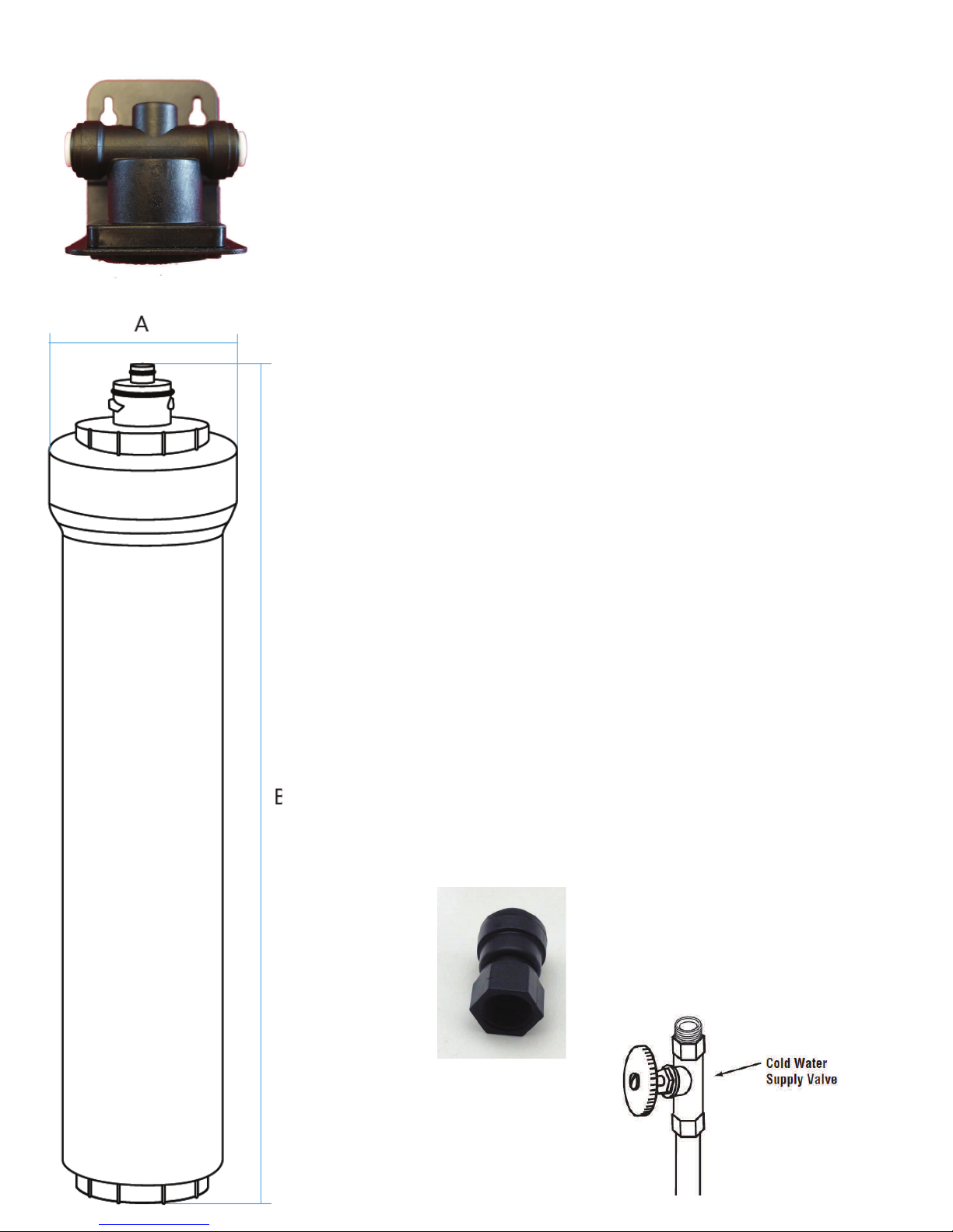
Figure 1.
Dimension A: 2.75 inches
Dimension B: 19 inches
Figure 2.
Female Adapter

Determine the length of tubing you will need from the filter
head INLETto the adapter by holding the tubing in place.
Do not kink the tubing as this will impede water flow. Cut
the desired length necessary for connecon making sure to
cut tubing straight with razor knife or tube cuer.
6. Insert the tubing from the adapter (figure 2) to the INLET
side of the filter head. (ARROW POINTING INWARD
TOWARD THE CENTER) SEE PAGE 5‐“Using Push‐In
Fings.”
7. Locate the Male threaded adapter. Connect this adapter
to the cold water hose disconnected in Step 4.
DO NOT OVERTIGHTEN.
8. Determine the length of the remaining tubing required
to connect from the filter head OUTLET to the adapter by
holding the tubing in place. Cut to the desired length.
FIGURE 3
9. Insert the tubing into the adapter (SEE PAGE 5‐“Using
Push‐In Fings.” Then insert the tubing into the OUTLET
side of the filter head (ARROW POINTING AWAY FROM
CENTER).
Male Adapter

10. Remove the sanitary cover from the cap. Ensure the filter mount O‐rings are
protruding from the top of the Cap. Unscrew the Cap from the sump. The
filter mount will sll be aached to the cap at this me. Take protecve
wrapping offof the filter cartridge and place into the sump. Proceed to thread
the Cap (with filter mount sll aached) back onto the sump unl ght.
Moisten the O‐rings with water. DO NOT use any
petroleum products to lubricate.
11. Align assembled filter with the lugs on the cap end
facing the front and back of the head. Push the cap end
into the head and then proceed to twist the assembly
clock‐wise 90 degrees to seal. ( A Quarter Turn).
The filter is now installed.
12.Turn on the cold water supply valve and open the fau‐
cet to flush air from the system. Run water for 2‐3
minutes to pre‐condion the filter. Close the faucet.
The system is now under pressure and can be inspected
for leaks.
Repair any leak before connuing use.
13.Flush the system twice for 2‐3 minutes before inial
use.

REPLACEMENTFILTERINSTRUCTIONS
1. Place towel under the filter system to collect any residual water during filter
change.
2. Twist the filter housing counter‐clockwise 90 degrees/a quarter turn to the right
and separate the housing from the head. The head has an internal shut‐offbuilt
in but there will be a momentary water spillage from the depressurizing of the
valve. This is normal.
3. Remove the cap from the housing/sump by unscrewing it. Separate the internal
filter from the filter mount and discard. Replace with new filter cartridge;
reaaching the filter mount to the filter cartridge, placing into the housing/sump
and reaaching and screwing down ghtly the cap.
4. Align assembled filter with the lugs on the cap end facing the front and back of
the head. Push the cap end into the head and then proceed to twist the as‐
sembly clock‐wise 90 degrees to seal. ( A Quarter Turn). The filter is now
installed.
Turn on the cold water supply valve and open the faucet to flush air from the
system. Run water for 2‐3 minutes to pre‐condion the filter. Close the
faucet. The system is now under pressure and can be inspected for leaks.
Repair any leak before connuing use.

LIMITEDWARRANTY
CFCI warrants this product to be free from defects in material and manufacture for a period of
3 years from date of purchase to the end‐user. This includes the head and bracket, cap, filter
mount and housing. O‐rings should be replaced if there are any signs of damage.
Filter is warranted for a period of 3 months from date of purchase against defects in
workmanship only.
CFCI MAKES NO OTHER WARRANTIES OR CONDITIONS, EXPRESS OR IMPLIED, INCLUDING, BUT
NOT LIMITED TO, ANY IMPLIED WARRANTY OR CONDITION OF MERCHANTABILITY OR FITNESS
FOR A PARTICULAR PURPOSE OR ANY IMPLIED WARRANTY OR CONDITION ARISING OUT OF A
COURSE OF DEALING, CUSTOMER OR USAGE OF TRADE. If the product fails to sasfy the
limited warranty during the warranty period, CFCI will repair or replace the product
at its discreon.
THISWARRANTYDOESNOTCOVERANYLABOR.
Limitaon of Liability: CFCI will not be liable for any loss or damage arising from this product,
whether direct, indirect, special, incidental, or consequenal, regardless of the legal theory
asserted, including warranty, contract, negligence or strict liability. Some states and countries
do not allow the exclusion or limitaon of incidental or consequenal damages, so the above
limitaon or exclusion may not apply to you.
Table of contents
Popular Water Filtration System manuals by other brands


Everpure
Everpure E10 Series Installation and operation guide

ph Miracle
ph Miracle Watermark user guide

AQUAPHOR
AQUAPHOR ONYX operating manual

Adey
Adey MagnaClean Micro 2 Installation and servicing instructions

Allfyll
Allfyll Oasis-UF instruction manual

amiad
amiad T Installation & maintenance instructions