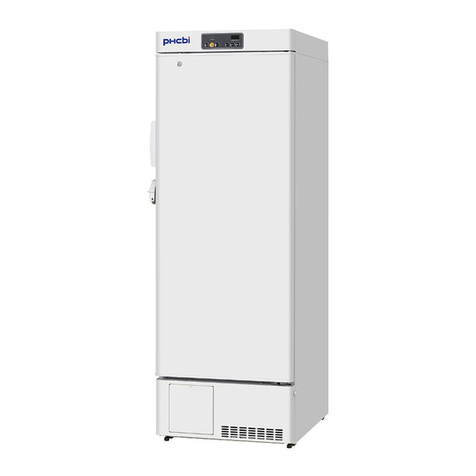
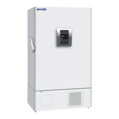
Phcbi PF-L5181W-PA User manual

English
Please read these instructions carefully before using this product, and save this manual for future use.
See page 22 for Model No.
PF-L5181W-PA
Laboratory Freezer
Operating Instructions
PF-L5181W-PA
Left Door
(Factory order made)

1
English
Note:
CONTENTS
PRECAUTIONS FOR SAFE OPERATION P. 2
CAUTIONS FOR USAGE P. 6
ENVIRONMENTAL CONDITIONS P. 7
PRODUCT DIMENSIONS P. 8
FREEZER COMPONENTS P. 9
CONTROL PANEL FUNCTIONALITY CHECK P. 12
INSTALLATION P. 13
START UP OF UNIT P. 15
OPERATING INSTRUCTIONS P. 15
ALARMS AND SAFETY FUNCTIONS P. 17
DEFROST P. 17
MAINTENANCE P. 18
STACKING TWO UNITS P. 20
TROUBLESHOOTING P. 21
SPECIFICATIONS P. 22
PERFORMANCE P. 23
SERVICE P. 24
SAFETY CHECK SHEET P. 25
1. No part of this manual may be reproduced in any form without the
express written permission of our company.
2. The contents of this manual are subject to change without notice.
3. Please contact our company if any point in this manual is unclear or if
there are any inaccuracies.
PHC Corporation of North America All rights reserved.

2
English
PRECAUTIONS FOR SAFE OPERATIONS
It is imperative that the user complies with this manual as it contains
important safety advice.
Items and procedures are described so that you can use this unit correctly and safely. If the
precautions advised are followed, this will prevent possible injury to the user and any other
person.
Precautions are illustrated in the following way:
WARNING
Failure to observe WARNING signs could result in a hazard to personnel
possibly resulting in serious injury or death.
CAUTION
Failure to observe CAUTION signs could result in injury to personnel and
damage to the unit and associated property.
Symbol shows;
this symbol means caution.
this symbol means an action is prohibited.
this symbol means an instruction must be followed.
Be sure to keep this manual in a place accessible to users of this unit.

3
English
PRECAUTIONS FOR SAFE OPERATION
Do not use the unit outdoors. Current leakage or electric shock may result if the unit is exposed to rain
water.
Only qualified engineers or service personnel should install the unit. Installation by unqualified
personnel may cause electric shock or fire.
Be sure to install the unit on a sturdy floor. If the floor is not strong enough or the installation site is not
adequate, injury may result from the unit falling or tipping over.
Never install the unit in a humid place or a place where it is likely to be splashed by water.
Deterioration of the insulation may result which could cause current leakage or electric shock.
Never install the unit in a flammable or volatile location. This may cause explosion or fire.
Never install the unit where acid or corrosive gases are present as current leakage or electric shock
may result due to corrosion.
Make sure a dedicated power source is used as indicated on the rating label attached to the unit.
Make sure to remove dust from the power supply plug before inserting in a power source. A dusty
plug or improper insertion may pose a hazard.
Use a power supply outlet with ground (earth) to prevent electric shock. If the power supply outlet is
not grounded, it will be necessary to have qualified engineers install a ground.
Never ground the unit through a gas pipe, water main, telephone line or lightning rod. Such
grounding may cause electric shock in the case of an incomplete circuit.
Do not insert metal objects such as a pin or a wire into any vent, gap or any outlet for inner air
circulation. This may cause electric shock or injury by accidental contact with moving parts.
Never store volatile or flammable substances in this unit. This may cause explosion or fire.
Never store corrosive substances in this unit. This may lead to damage to the inner components or
electric parts.
If this unit is to be used for storing poisons, radioactive material or other harmful products, ensure
that it is in a safe area. Failure to do so may lead to an adverse effect on the health of personnel in the
area and the local environment. In this case, a request for repair or maintenance will necessitate a safety
check sheet for maintenance personnel.
WARNING

4
English
PRECAUTIONS FOR SAFE OPERATION
Always disconnect the power supply to the unit prior to any repair or maintenance of the unit in order
to prevent electric shock or injury.
Ensure you do not inhale or consume medication or aerosols from around the unit at the time of
maintenance. These may be harmful to your health.
Never splash water directly onto the unit as this may cause electric shock or short circuit.
Never disassemble, repair, or modify the unit yourself. Any such work carried out by an unauthorized
person may result in fire or injury due to a malfunction. Component parts shall be replaced with like
components to minimize the risk of possible ignition due to incorrect parts or improper service.
Disconnect the power supply plug if there is something wrong with the unit. Continued abnormal
operation may cause electric shock or fire.
If the unit is to be stored unused in an unsupervised area for an extended period, ensure that children do
not have access and that doors cannot be closed completely.
The disposal of the unit should be accomplished by appropriate personnel. Risk of child entrapment.
Before you throw away your old freezer take off the doors to prevent accidents such as suffocation.
Make sure to prepare a safety check sheet when you request any repair or maintenance for the safety of
service personnel.
Select a level and sturdy floor for installation. This precaution will prevent the unit from tipping.
Improper installation may result in water spillage or injury from the unit tipping over.
Connect the unit to a power source as indicated on the rating label attached to the unit. Use of any
other voltage or frequency other than that on the rating label may cause fire or electric shock.
Fix the shelves securely. Incomplete installation may cause injury or damage
When removing the plug from the power supply outlet, grip the power supply plug, not the cord.
Pulling the cord may result in electric shock or fire by short circuit.
Do not use mechanical devices or other means to accelerate the defrosting process, other than
those recommended by the manufacturer.
Do not damage the refrigerant circuit.
WARNING

5
English
PRECAUTIONS FOR SAFE OPERATION
Never damage or break the power supply plug or cord. Do not use the supply plug if its cord is
loose. This may cause fire or electric shock. If the supply cord is damaged, it must be replaced by the
manufacturer, its service agent or similarly qualified person in order to avoid a hazard.
Do not touch any electrical parts such as the power supply plug or any switches with a wet hand. This
may cause electric shock.
Do not climb onto the unit. This may cause injury by tipping or damage to the unit.
Do not store bottle or cans in the freezer. This may cause injury by broken of containers due to the
frozen.
Do not touch any stock (especially metal objects) in the freezer with a wet hand. This may cause
frostbite.
Always hold the handle when closing the door. This will reduce the likelihood of a trapped finger.
Do not lean on the door. This may cause injury if the unit tips over.
Always disconnect the power supply plug before moving the unit. Take care not to damage the power
cord. A damaged cord may cause electric shock or fire.
Dispose of water in the evaporation tray completely prior to the movement. Spilled water or
splashed water may cause current leakage or electric shock.
Be careful not to tip over the unit during movement to prevent damage or injury.
Always disconnect the power plug when the unit is not used for long periods.
Make sure to check the setting value when starting up the operation after the power failure or
power off. A change of setting value may cause damage to contents.
Do not put the packing plastic bag within reach of children as suffocation may result.
Every time you disconnect the unit from the power source, make sure you wait at least 5 minutes
to plug it back on. This protects the unit compressor and avoid possible damages.
Do not use electrical appliances inside the compartments of the appliance, unless they are the type
recommended by the manufacturer
CAUTION

6
English
CAUTIONS FOR USAGE
1. If the unit is unplugged or the power to the unit is interrupted, do not restart the unit for at least 5 minutes.
This protects the compressor.
2. This inner cabinet is refrigerated by the forced circulation of cooled air inside the chamber. Ensure that
the intake and exhaust vents are not blocked. Adequate space should be provided between the items
inside the unit to allow air circulation.
3. Never store corrosive materials such as acid or alkali unless the container is completely sealed up.
Corrosion may lead to failure of the unit in time.
4. Once the chamber temperature has stabilized, put the items into the chamber in small batches to
minimize the temperature increase.
5. Place items on the shelves and leave a space between the wall of the cabinet and the contents to allow
air circulation. Do not place items on the floor of the chamber.
6. Always close the door firmly. The door check lamp is lit when the door is open. The alarm buzzer sounds
after two minutes the door opening. The buzzer can be canceled automatically when the door is closed.
7. Always open and close the door gently. Rough operation may lead to stored items falling down,
incomplete closing, or damage of door gasket.
8. In the freezer compartment, put stored items on the shelves and do not let them contact the wall.
9. If an instrument requiring a power source is to be placed inside the cabinet, the cable can be led through
the access port on the right side of the cabinet. After using the port, the rubber cap and insulation should
be replaced to seal the access port. Failure to do this can affect the temperature uniformity inside the
cabinet and lead to condensation on the outside of the access port.
10. Do not clean the unit with scrubbing brushes, acid, thinner, solvents powdered soap, cleanser or hot
water. These agents can scratch the paint or cause it to peel. Plastic and rubber parts can be easily
damaged by these materials. Especially never use any volatile solvent to clean the plastic or rubber
parts. When a neutral dishwashing detergent is used to clean the unit, wipe it up thoroughly with a cloth
soaked in clean water.
11. If condensation forms on the door or frame surface, wipe it off with a dry soft cloth.
12. The heat discharge pipe is attached inside both the side and rear frame. The frame sometimes gets hot
at the start-up of the operation, but this does not mean that a malfunction has occurred.
13. Handling, moving and use of the freezer must be done with caution to avoid either damaging the
refrigerant tubing or increasing the risk of a leak
7
English
ENVIRONMENTAL CONDITIONS
This equipment is designed to be safe at least under the following conditions:
1. Indoor use: For intended use on laboratories;
2. Altitude up to 2000 m;
3. Ambient temperature 20oC to 24oC;
4. Maximum relative humidity 75% for temperature up to 24oC decreasing linearly to 50%;
5. Main supply voltage fluctuations not to exceed ±10% of the nominal voltage;
6. Other supply voltage fluctuations as stated by the manufacturer;

8
English
PRODUCT DIMENSIONS
OVERALL PRODUCT PF-L5181W-PA (Solid Door)
Width (up to hinge cover)
23 27/32” (606mm)
Height (up to hinge cover)
34 5/32” (867mm)
Depth (up to Solid Door)
23 21/32″ (600mm)
Door Height
30 5/8″ (777mm)
Note: Power Cord 60” (152.4cm) long.
Left Door
(Factory order made)

9
English
FREEZER COMPONENTS
1. Access Port: Allow installation of
temperature sensor inside the
cabinet for the purpose of external
monitoring.
2. Door Lock: Turn the key clockwise
through 180 degrees to lock the
door.
3. Control Panel: The operation status
is displayed on this panel;
temperature setting is also available.
Refer to page 11 for details.
①
②
③

10
English
FREEZER COMPONENTS
PLEASE NOTE: The shelves position is fixed and is not adjustable.
1. Circulation Fan:Helps to keep a
consistent temperature throughout
entire chamber.
2. Powder coated wire shelves:
Evaporator position is fixed and
include wires to support the product.
3. Magnetic door gasket: Magnetic
force ensures the door is sealed to
provide optimum performance and
temperature uniformity.
4. Adjustable legs: Use these to level
the freezer.
5. Door Open Sensor: Signals alarm if
door is left open.
①
32
1a
sd
②
③
④
5

11
English
FREEZER COMPONENTS
Control Panel
1. Alarm buzzer stop key (BUZZER): Press this key to silence the buzzer in the event that the alarm
operates and the buzzer sounds. See page 17 for detail.
2. Alarm test key (ALARM TEST): Buzzer will sound. See page 17 for detail.
3. Defrost key: Defrost will started by pressing this key for more than 5 seconds.
4. Set key (SET): Pressing this key activates temperature set mode. By pressing the key again after setting,
the set value is accepted.
5. Down Arrow ( ): Pressing this down arrow key in the setting mode causes the numerical value to go
down in 1°C increments. A long press of this key will enter offset mode. Offset mode is used to calibrate
the temperature display.
6. Up Arrow ( ): Pressing this up arrow key in the setting mode causes the numerical value to go up in 1°C
increments. A long press of this key will enter or exit the key lock mode.
7. Door check lamp (DOOR): This lamp is lit when the door is open. See page 17 for detail.
8. Alarm lamp (ALARM): This lamp is lit during alarm condition. See page 17 for detail.
9. Temperature display: This indicator shows the chamber temperature, set temperature, or error code.
9
8
7
6
5
4
3
2
1
1

12
English
CONTROL PANEL FUNCTIONALITY CHECK
The first time the unit is powered on, you must insure the control panel functionality by following the operation
described in table 1:
Table 1 Manual check of Control panel
Operation
Key operated
Control panel description
1
Connecttothepower
source.
-----
Five seconds after turning on the unit, the temperature inside the
unit should appear on temperature display (LED Screen).
2
Press “Alarm Test”
key.
ALARM TEST
Two seconds after pressing the button, the buzzer should sound
every 1 second. Let the buzzer sound at least 3 times.
3
Press “Alarm Test”
key.
ALARM TEST
Within 2 second of pressing the button, the buzzer should stop.
(The buzzer should stop sounding after two second of pressing
the button).
4
Press “SET” key.
SET
Within 2 seconds of pressing the button, you will hear a beep
once. The display will show “-20” on LED Screen and it will start
blinking.
5
Press “△” key.
Within 2 seconds of pressing the button, you will hear a beep
once. The display will show “-19” on LED Screen and it will start
blinking.
6
Press “△” key two
times.
Within 2 seconds of pressing the button, you will hear a beep
once. The display will show “-17” on LED Screen and it will start
blinking.
7
Press “▽” key three
times.
Within 2 seconds of pressing the button, you will hear a beep
once. The display will show “-20” on LED Screen and it will start
blinking.
9
Open the door
-----
Two seconds after opening the door, the door check lamp will
turn red.
10
Close the door
-----
Two seconds after closing the door, the door check lamp will turn
off.
11
Open the door
-----
Two seconds after opening the door, the door check lamp will
turn red.
12
Keep the door open
-----
After 120 seconds, the alarm lamp will turn red and will start
beeping every second. Let the unit beep at least 3 times.
13
Close the door
-----
Two seconds after closing the door, the door check lamp will turn
off.
“

13
English
INSTALLATION
Installation site
To operate this unit properly and to obtain maximum performance,
install the unit in a location with the following conditions:
1. A location not subjected to direct sunlight
Installation in a location subjected to direct sunlight might lead to inadequate cooling.
2. A location with adequate ventilation
Always keep in front of air intake and exhaust area open for free air circulation. Poor ventilation will result
in inadequate cooling.
3. A location away from heat generating sources
Avoid installing the unit near heat-emitting appliances such as gas ranges or stoves. Heat can reduce
refrigeration efficiency.
4. A location with a sturdy and level floor
Install the unit on a sturdy floor to avoid vibration and noise. Placing the unit on an unsteady floor may cause
vibration and noise.
WARNING
Be sure to install the unit on a sturdy floor. If the floor is not strong enough or the installation site is not
adequate, this may result in injury from the unit falling or tipping over.
CAUTION
Select a level and sturdy floor for installation. This precaution will prevent the unit from tipping. Improper
installation may result in water spillage or injury from the unit tipping over.
5. A location not prone to high humidity
WARNING
Do not use the unit outdoors. Current leakage or electric shock may result if the unit is exposed to rain
water.
Never install the unit in a humid place or a place where it is likely to be splashed by water.
Deterioration of the insulation may result which could cause current leakage or electric shock.
Do not install the unit under water pipes or steam pipes. Deterioration of the insulation may result which
could cause current leakage or electric shock.
6. A location without a flammable or corrosive gas
Avoid placing the unit where chemicals are stored or gases are produced. Also avoid areas where there is
a great deal of dust.
WARNING
Never install the unit in a flammable or volatile location. This may cause explosion or fire.
Never install the unit where acid or corrosive gases are present as current leakage or electric shock may
result due to corrosion.

14
English
INSTALLATION
7. A location with enough space to ensure proper ventilation
Allow for a 1/4" (6.35 mm) space on left side and at the top. Leave 2 ½” (6.35 cm) minimum clearance on
the right side (hinge side) to allow for the door to swing open.
Installation
1. Remove the packaging materials and tapes. Remove all transportation packaging materials and
tapes. Open the doors and ventilate the unit. If the outside panels are dirty, clean them with a diluted
neutral dishwashing detergent (Undiluted detergent can damage the plastic components. For the
dilution, refer to the instruction of the detergent). After cleaning with the diluted detergent, always wipe it
off with a wet cloth, then wipe the panels with a dry cloth.
2. Door handle installation. Remove the two plugs from the door where you will attach the door handle.
Apply door handle, plastic washer and screw and fasten the screw. For floor-level installation the handle
should be mounted at the higher location. For stacking above another compatible unit, the handle should be
mounted at the lower location.
3. Ground (earth)
WARNING
Use a power supply outlet with ground (earth) to prevent electric shock. If the power supply outlet is not
grounded, qualified personnel must install a ground.
Never ground the unit through a gas pipe, water main, telephone line or lightning rod. Such grounding
may cause electric shock in the case of an incomplete circuit.
4. Access Port: If a temperature sensor is to be placed inside the cabinet, the cable
can be led through the access port on the right side of the cabinet. After using the port, a
rubber cap and insulation should be reinstalled to seal the access port. Make a cut on the
rubber cap and pass the sensor wire through it. (Fig. 1) Failure to do this can affect the
temperature uniformity inside the cabinet and lead to condensation on the outside of the
access port.

15
English
START-UP OF UNIT
The following procedures should be adhered to for initial start-up and continuous operation.
1. Connect the unit to dedicated power supply. Do not put any product in the unit at this time.
2. Set the desired temperature. The unit is preset to operate at -20°C. This is the optimal storage
temperature to maintain vaccine and biologic products within -15°C to -25°C throughout the usable
storage area.
3. Confirm that the chamber temperature is at the desired temperature.
4. When you are satisfied that the unit is working correctly, begin slowly placing product into the chamber to
minimize the temperature rise. Avoid long or excessive door openings to insure stored product integrity.
OPERATING INSTRUCTIONS
Temperature Setting
Table 2 shows the basic operation method. Perform key operation in the sequence indicated in the table. The
example in the table is based on the assumption that thefreezer temperature is -18oC.
Note: The unit is set at the factory at -20oC.
Table 2 Basic operation procedure (Example of setting: Freezer @ -19oC)
Operation
Key operated
Display after the key operation
1
Connecttothepowersource.
-----
The current freezer temperature
is displayed after 5 seconds of
connecting the unit to the power
source. When freezer
temperature is higher than
-15°C, HI is displayed and LO
is displayed when lower than –25 C.
2
Press SET key.
SET
The digits of the temperature display flash.
3
Set to -19 by using the down arrow
key.
Pressing and releasing the down
arrow key shifts down the set point
by 1°C increments.
4
Press and release SET key.
SET
The value (-19) is stored in
memory and the current freezer
temperature is displayed.
Note:
If no key has been pressed for 90 seconds in the temperature set mode, the display mode returns automatically
to the temperature display mode. In this case, the chamber temperature setting is not changed. The freezer
temperature can be set in the range between -15°C and -25°C. The guaranteed temperature with no load at an
ambient temperature of 22°C is -15 to -25°C.

16
English
OPERATING INSTRUCTIONS
Calibration Procedure
The difference between chamber and indicated temperature can be arranged by key operation.
As an example, Table 3 shows the procedure in case actual freezer temperature is -19°C as indicated on a
NIST traceable thermometer placed in the center of the chamber and displayed temperature is -20°C; change
the displayed temperature to -19°C.
Table 3 Offset setup procedure
Operation
Key operated
Display after the key operated
The current freezer temperature
is displayed.
1
Press and hold the down arrow key
more than 5 seconds.
The digits of the temperature
display flash.
2
Set to -19 by using
Up arrow key.
Pressing the key shifts up the
figure by 1°C. Repeat
until flashing digit turns to 1.
3
Press the set key.
SET
The current adjusted temperature
(offset by +1 degree) is displayed.
Key Lock Operation
This unit incorporates a key lock feature that can inhibit tampering using the keys on the control panel.
The key lock is set to OFF at the factory.
Display
Mode
Function
LOC
Key lock ON
Temperature change disabled
Table 4 Key lock setup procedure (Example: Key lock OFF ⇒Key lock ON)
Operation
Key operated
Display after the key operated
The current freezer temperature is displayed.
1
Press and hold the up arrow
key for about 5 seconds.
Display alternates
Between LOC and
actual temperature.
Note: Key lock can be set any time when the current freezer temperature is displayed.

17
English
ALARMS AND SAFETY FUNCTIONS
This unit has the alarm and safety functions shown in Table 5, and also a self-diagnostic function.
Table 5 Alarms and safety functions
Kind of alarm
or safety
Situation
Indication
Buzzer
Safety operation
High
temperature
alarm
If the chamber temperature
exceeds the set temperature
more than -15oC.
Alarm lamp is lit.
Intermittent tone
after a delay of 15
minutes.
-----
Low
temperature
alarm
If the chamber temperature
is lower -25oC than the set
temperature .
Alarm lamp is lit.
Intermittent tone
after a delay of 15
minutes.
-----
Power failure
alarm
In the event of a power
failure or disconnection of
power supply plug from the
outlet
Display shuts off.
-----
-----
Door alarm
When door remains open for
more than 2 minutes.
Door lamp is lit.
Intermittent tone
after a delay of 2
minutes.
-----
Auto return
If a key operation is not
performed for about 90
seconds in each setting mode.
Chamber temperature is
displayed.
-----
Setting mode is
canceled.
Key lock
When the key lock is ON.
Alternate LOC and actual
temperature.
-----
Key input is disabled.
Thermal sensor
abnormality
If the thermal sensor goes
open (E10) or short circuit
(E1S).
Either E10 or E1S is displayed.
-----
****
Defrost sensor
abnormality
If the defrost sensor has a
short circuit (E2S).
Note: Defrost sensor is present
in the unit, but the defrost
sensor is not operational.
E2S is displayed.
-----
Only manual defrost
is available in the
equipment.
The unit will alarm if
the defrost sensor is
not present in the unit
Note:
The alarm can be canceled by pressing the alarm buzzer stop key (BUZZER).
After a power failure, the unit will resume operation with the last saved setting temperature point on display
memory.
DEFROST
The defrosting is activated when DEF key is pressed more than 5 seconds.
Remove and store the contentto other freezer before starting the defrosting. Place cotton bath towels atthe bottom
of the freezer chamber before the start of defrosting as the defrost water will fall. Keep the door open in order to
quicken defrosting. If bath towels are soaked, remove from the chamber, dry them and replace to prevent water to
drip out of chamber. Do not try to physically remove ice as that may cause the damage to the evaporator. After
defrosting, remove wet towels, dry inside chamber with dry soft clothes before re-start of the unit.
Pressing the DEF key for more than 5 seconds will restart the operation of the freezer.

18
English
MAINTENANCE
WARNING
Always disconnect the power supply to the unit prior to any repair or maintenance of the unit in order to
prevent electric shock or injury.
Ensure you do not inhale or consume medication or aerosols from around the unit at the time of
maintenance. These may be harmful to your health.
Cleaning
•Clean the unit once a month. Regular cleaning keeps the unit looking new.
•Use a dry cloth to wipe off small amounts of dirt on the outside and inside of the unit and all accessories. If
the outside panels are dirty, clean them with a diluted neutral dishwashing detergent. (Undiluted detergent
can damage the plastic components. For the dilution, refer to the instruction of the detergent.) After the
cleaning with the diluted detergent, always wipe it off with a wet cloth. Then wipe off the cabinet or
accessories with a dry cloth.
•Never pour water onto or into the unit. Doing so can damage the electrical insulation and may cause electric
shock or short circuit.
•The compressor and other mechanical part are completely sealed. This unit requires absolutely no
lubrication.
•Clean the condenser coils regularly. They are located behind the base grille (kickplate). Coils may need to
be cleaned as often as every other month. This may help save energy. Please refer to next section
“Removing Base Grille” to access condenser for cleaning.

19
English
Removing Base Grille
You must remove the base grille to access the condenser coils for cleaning
Procedure to remove base grille:
1. Open the freezer door
2. Using a Philips screwdriver, remove the two screws.
3. Remove the base grille
4. Installation is reversal of removal.
Screws
Table of contents
Other Phcbi Freezer manuals

Phcbi
Phcbi MDF-U33V Series User manual

Phcbi
Phcbi MDF-MU549DH User manual

Phcbi
Phcbi MDF-MU549DHL User manual

Phcbi
Phcbi MDF-DU702VXC User manual

Phcbi
Phcbi MDF-U5412 User manual

Phcbi
Phcbi MDF-C8V1 User manual

Phcbi
Phcbi MDF-DU702VH User manual

Phcbi
Phcbi MDF-DU701VH User manual

Phcbi
Phcbi MDF-DU900V User manual

Phcbi
Phcbi MDF-U55V User manual

Phcbi
Phcbi MDF-DU900VC User manual

Phcbi
Phcbi MDF-MU539D User manual

Phcbi
Phcbi MDF-DU702VHA User manual

Phcbi
Phcbi MDF-DU302VX User manual

Phcbi
Phcbi MDF-MU500H User manual

Phcbi
Phcbi MDF-U74V-PR User manual

Phcbi
Phcbi MDF-MU339 User manual

Phcbi
Phcbi MDF-C2156VAN Series User manual

Phcbi
Phcbi MDF-U54V Series User manual

Phcbi
Phcbi MDF-U74V Series User manual