1-5-6 T6500DC
CABINET DISASSEMBLY INSTRUCTIONS
[ 21PV375/ ( 01, 07, 39, 58 ) ]
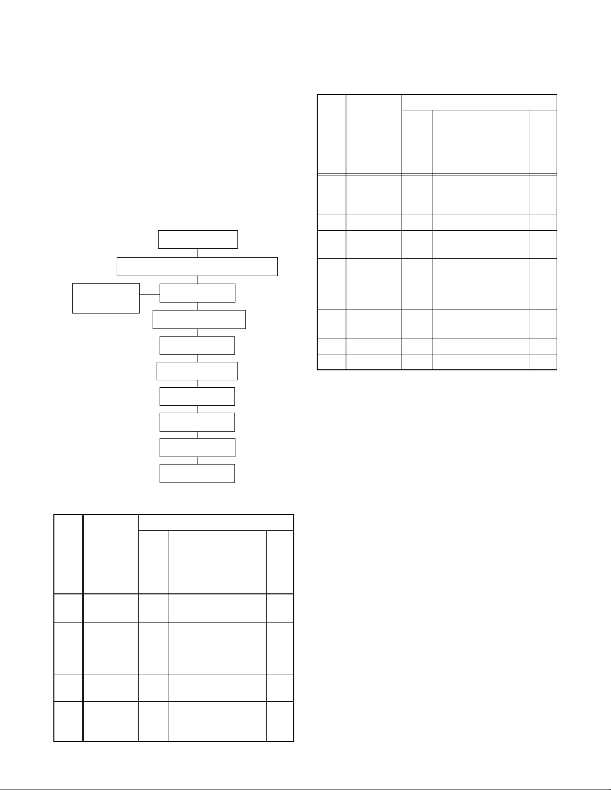
1. Disassembly Flowchart
This flowchart indicates the disassembly steps for the
cabinet parts, and the CBA in order to gain access to
item(s) to be serviced. When reassembling, follow the
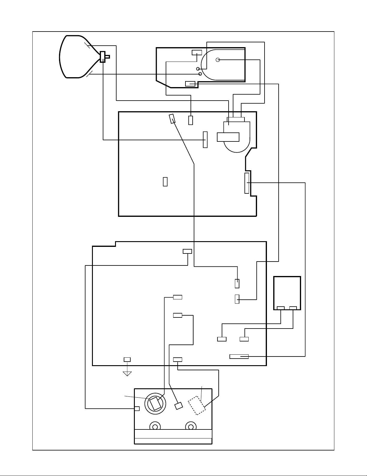
steps in reverse order. Bend, route and dress the
cables as they were.
Caution !!
When removing the CRT, be sure to discharge the
Anode Lead of the CRT with the CRT Ground Wire
before removing the Anode Cap.
2. Disassembly Method
(1): Order of steps in Procedure. When reassembling,
follow the steps in reverse order.These numbers
are also used as the identification (location) No. of
parts in Figures.
(2): Parts to be removed or installed.
(3): Fig. No. showing Procedure of Part Location.
(4): Identification of part to be removed, unhooked,
unlocked, released, unplugged, unclamped, or
desoldered.
S=Screw, P=Spring, L=Locking Tab, CN=Connec-
tor, *=Unhook, Unlock, Release, Unplug, or
Desolder
2(S-2) = two Screw (S-2)
(5): Refer to the following "Reference Notes in the
Table."
Reference Notes in the Table
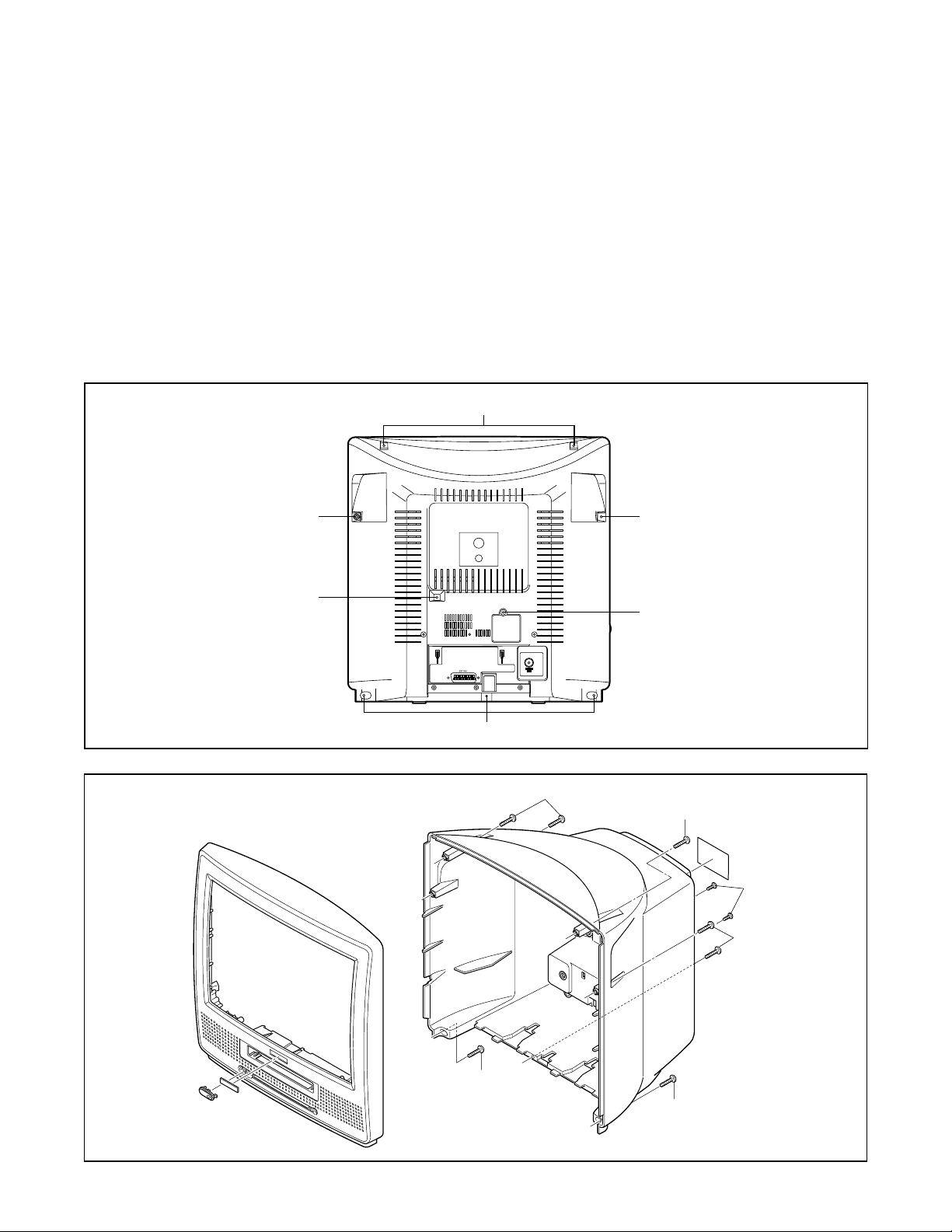
1. Removal of the Rear Cabinet.
Remove four screws (S-1) and two screws (S-2).
Disconnect connector CN151 and remove the Rear
Cabinet.
Caution !!
Discharge the Anode Lead of the CRT with the CRT
Ground Wire before removing the Anode Cap.
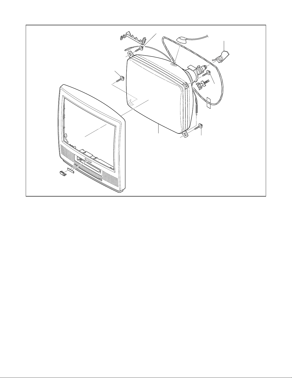
2. Removal of the Power Unit and Tray Chassis Unit.
Discharge the Anode Lead of the CRT with the
CRT Ground before removing the Anode Cap.
ID/
LOC.
No.
PART
REMOVAL
Fig.
No.
REMOVE/
*UNHOOK/
UNLOCK/RELEASE/
UNPLUG/DESOL-
DER
Note
[1] Rear
Cabinet 1,2,5 7(S-1), 2(S-2),
*CN151 1
[2]
Power Unit
and Tray
Chassis
Unit
3,4,5
Anode Cap, *CN501,
*CN551, *CN601,
CRT CBA, Power
Knob
2
[3] Power Unit 3,5 *CN502, *CN552,
*CN602 3
[4]
Tray
Chassis
Unit
3 ---------- -
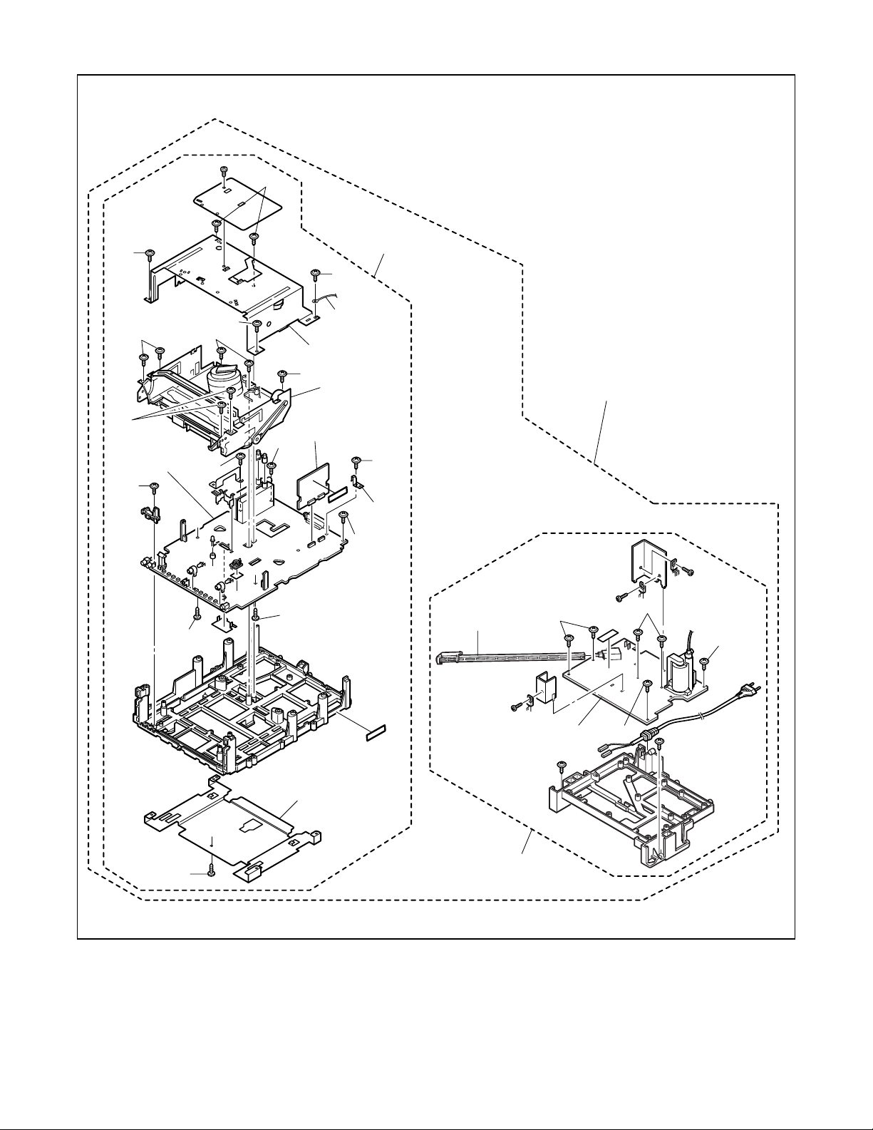
[1] Rear Cabinet
[4] Tray Chassis Unit
[9] Text CBA
[8] Deck Unit
[7] Bottom Plate
[6] Top Shield
[10] Main CBA
[3] Power Unit
[2] Power Unit and Tray Chassis Unit
[5] H.V./Power
Supply CBA
[11] CRT
[5]
H.V./Power
Supply
CBA
36(S-3) 4
[6] Top Shield 3 5(S-4), CL604 5
[7] Bottom
Plate 3(S-5) 6
[8] Deck Unit 3, 5
7(S-6), (S-7), (S-8),
Desolder *(CN201,
CL401, CL402,
CL403)
7
[9] Text CBA 3, 5 (S-9), *CN751,
*CN752 8
[10] Main CBA 3 4(S-10) 9
[11] CRT 4 4(S-11) 10
↓
(1)
↓
(2)
↓
(3)
↓
(4)
↓
(5)
ID/
LOC.
No.
PART
REMOVAL
Fig.
No.
REMOVE/
*UNHOOK/
UNLOCK/RELEASE/
UNPLUG/DESOL-
DER
Note