Phoenix Ovens Flametree User manual

PHOENIX OVENS Installation & Operation Manual 1
Installation & Operation Manual
Stone Heath Ovens—Gas & Wood Fired
DO NOT DISCARD
KEEP THIS MANUAL WITH OVEN AT ALL TIMES

PHOENIX OVENS Installation & Operation Manual 2
CONTENTS
INSTALLATION
SAFETY INFORMATION AND WARNINGS 3
DESCRIPTION OF PHOENIX OVEN 5
EQUIPMENT REQUIRED 6
PRELIMINARY CHECKS 7
INSTALLATION PROCEDURE 8
EXHAUST DESIGN 9
BUILDING IN 13
GAS SYSTEM OVERVIEW 14
CONTRACTORS RESPONSIBILITY 14
OVEN CONTROL COMPONENTS
& FUNCTIONS 15
CONTROL FAULTS & INDICATORS 16
CONNECTION OF GAS SYSTEM 17
COMMISSIONING 18
PREHEAT FIRE 18
OVEN OPERATION
OPERATION OF OVEN & COOKING 20
FIRING UP TO COOK 20
REGULAR FLUE MAINTENANCE 22
TECHNICAL REFERENCE
OVEN MATERIALS. 24
GAS TRAIN SCHEMATIC 24
ELECTRICAL SCHEMATIC 25
INTERLOCK DEVICE 26
START-UP PROCEDURE 27
REGULAR MAINTENANCE 28
WARRANTY
WARRANTY CERTIFICATE 29
ECFIA GENERAL MSDS 30
INTRODUCTION
This guide provides detailed installation information for
the Installation & Operation of Phoenix Ovens’ in a
commercial construction situation.
For additional information or assistance please contact
our technical department via email:
technical@phoenixovens.com or technical director,
Mr. Greg Thomson via email: greg@phoenixovens.com
WARNING: Improper installation, adjustment,
alteration, service or maintenance can result in
property damage, injury or death.
Read the installation, operation and maintenance
instructions thoroughly before installing or servicing
this equipment.
RETAIN THIS MANUAL WITH THE OVEN AT ALL
TIMES FOR FUTURE REFERENCE.
CONTACT DETAILS
PHOENIX OVENS PTY LTD
(ABN 81 150 166 439)
PO Box 1258 SPRING HILL, QLD, AUSTRALIA 4006
Phone: +61 458 772 253
Phone: +61 468 424 789
Web: www.phoenixovens.com
Additional copies of this manual can be supplied, please
contact our office or your local representative.
STANDARDS
The Phoenix Oven has been designed and manufactured
to comply with relevant codes……
AS/NZS 60335 (#'5200-0145-01A')
RoHS & W.E.E.E. Compliant
EN 298 with reference to the “Gas Appliance
Directive” (GAD 90/396/EEC)
EN 126
Directive 91/155/CEE

PHOENIX OVENS Installation & Operation Manual 3
WARNING: Improper installation, adjustment, alteration, service or maintenance can
result in property damage, injury or death. Read the installation, operation and
maintenance instructions thoroughly before installing or servicing this equipment
It is recommended that this oven be installed only by professional personnel as
specified herein.
IMPORTANT: Consult your local gas supplier for a statement outlining the
procedure to be followed in the event you smell gas.
Post the statement in a prominent location near the oven.
FOR YOUR SAFETY
Never use gasoline, gasoline-type lantern fuel, kerosene, charcoal lighter
fluid or similar liquids to start or ‘freshen up’ a fire in this oven.
Keep all such liquids well away from the oven when in use.
A MAJOR CAUSE OF OVEN RELATED FIRES IS FAILURE TO MAINTAIN REQUIRED
CLEARANCES (AIR SPACES) TO COMBUSTIBLE MATERIALS.
IT IS VERY IMPORTANT THAT THIS OVEN BE INSTALLED ONLY IN CCORDANCE
WITH THE INSTRUCTIONS CONTAINED IN THIS MANUAL.
NOTE: Installation of the exhaust system should comply with local and national
codes.
The minimum mantle extension areas to be covered with relationship to the door
opening of the oven for combustible floors. At least the following areas shall be
specified (See Page 7):
750 mm (30 inches ) to each side of the door opening.
1000mm (39 inches ) in front of the door opening.
SAFETY INFORMATION & WARNINGS
WARNINGS:
1. Do not pack required air spaces with insulation or other materials.
2. If this oven is not properly installed, a fire may result. To reduce the risk of fire, fol-
low the installation instructions contained in this manual refer to pg. 8
3. Please read this entire manual before you install the oven. Failure to follow instruc-
tions may result in property damage, bodily injury, or even death.
4. The oven flue should be inspected at least four times a year to determine If creosote
buildup has occurred. If creosote has accumulated, it should be removed to reduce
risk of fire.
5. Do not use products not specified for use with this oven.
6. Do not construct a large fire near the oven mouth. If flame spills out of the oven
opening, you are over firing. Over firing can create a hazardous situation.

PHOENIX OVENS Installation & Operation Manual 4
SECTION1
INSTALLATION

PHOENIX OVENS Installation & Operation Manual 5
The Phoenix Oven utilizes wood or gas or a combination of both to perform regular
baking of foods in particular pizza. The basic oven is available in various different sizes.
The oven comprises a ¼”(5mm) mild steel outer skin of two sections, top and base.
The base includes four SHS legs supporting the floor of the pizza oven. The refractory
lining of the base utilizes ’High Alumina’ bricks as the hot face. The floor is insulated by a
layer of vacuum form board sheet.
The top section of the pizza oven has a steel outer shell as mentioned. The inside hot
face cavity is made of ceramic castable. The castable used is rated by a factor of two to
withstand the hottest possible burning in a naturally aspirated timber or gas fired
environment.
Externally the oven is covered in a further 50mm (2”) of ceramic wool to act as a further
insulating barrier. Typical cold face temperature is 45°C (110°F ) with a typical internal
temperature of 450°C (850°F ).
It is important to allow 25mm (1”) air gap between the outer face of the insulation
and any adjacent wall or cladding.
Typically the oven is then ”built in” using an architectural wall such as brick or firecheck
plasterboard (refer to the installation instructions in this manual). The oven has been
designed to operate reliably and safely in all environments. Phoenix Ovens have a
standard training course for oven operators available on request.
IDENTIFICATION OF PARTS
OVEN TOP (as shipped.) OVEN BASE (as shipped.)
DESCRIPTION OF PHOENIX OVEN

PHOENIX OVENS Installation & Operation Manual 6
The following equipment will be required in order to lift, maneuver and position the
oven:
Pallet trolley
Lifting frame
Chain block/winch 2 tonne.
D shackles 75mm / 3inch, 2 off.
Wire/StrapSling 2 tonne.
2 x 1000-kg chains or wire
Sling 3 metres long.
Long blade knife
Glue pot and brush
Exploded View of Flametree Model Oven
Oven Legs 4
Oven Base assemble 1
Gas System 1
Hearth 1
Lintel with swing door 1
Oven vTop Assemble 1
External Insulation 1
Exhaust transition with damper. 1
Gasket 1
Controller 1
Exhaust filter 1
EQUIPMENT REQUIRED

PHOENIX OVENS Installation & Operation Manual 7
The oven is transported by truck, ship or plane to its destination. The oven comes in
two halves, top and bottom weighing between 1100kg - 1800kg (2500 - 4000lbs.) and
400 - 1000kg . (880 – 2200.lbs) respectively. The consignment document is a good
check to establish oven weight.
Once on the ground, the method of installation is dependent on the difficulties of site
access. If there is sufficient width and no stairs, the oven can be moved by pallet
trolley to its desired location.
A mobile ’A’ frame or scaffold is then assembled to lift the top section. The base is
then wheeled in on the pallet trolley and placed underneath (Diagram 4).
In the cases where there are narrow corridors and stairs, both halves of the oven must
be individually placed on their side on a pallet trolley and moved through the narrow
passages.
ELEVATOR/LIFT: The oven half will fit into a standard elevator (Diagram 1). Note: We
recommend you check elevator load capacity before moving oven.
STAIRS: There must be sufficient width to install the ’A’ frame to move the halves up
the stairs. If there are too many stairs or the corridor has corners that are too sharp, or
the opening is narrower than 2’6” (700mm), the oven cannot be installed without
modifications to the building.
TIMBER FLOOR: Investigation must be made to ensure it will support the oven. For
installation purposes, we utilize thick sheets of ply to spread the weight of the oven
when we transport it over any surface, which may be damaged by the wheels of the
pallet trolley.
The minimum mantle extension areas to be covered with relationship to the door
opening of the oven for combustible floors. At least the following areas shall be
specified:
1) 750 mm (30“) to each side of the door
opening.
2) 1000mm (39”) in front of the door
opening.
PRELIMINARY CHECKS

PHOENIX OVENS Installation & Operation Manual 8
Prior to installing oven it is important to visit the installation site to determine if there are
doorways narrower than the oven in an upright position (normal).
If there are no narrow doorways, the oven can be kept in the horizontal plane i.e.
not put in the vertical plane to go through doorways.
The oven has been designed to fit through any standard doorway on its side and to
fit in any standard elevator.
INSTALLATION PROCESS:
1. Take the Oven to the site. Remove base from the pallets. Do not remove
plywood from top of base. This holds the fire-brick floor in position until
the oven is in position to have the top section assembled to the base.
2. Carefully remove the equipment stored beneath base and store in a secure
location. This equipment will be required later for assembly.
3. Lift TOP section from truck to pallet trolley using hotel crane or mobile crane
and place on pallet trolley. NOTE if the oven must go through narrow
doorways you need to place it on the trolley on its side plane. When lifting the
TOP, lift from top edge of the oven to enable this heavy item to be lifted onto
its side.
4. Move TOP to kitchen location.
5. Now lift base onto its side on the pallet trolley. DO NOT REMOVE PLYWOOD
FROM TOP OF BASE.
6. Remove legs from oven base to reduce its horizontal width (if necessary).
Carefully move this section of oven to kitchen location.
IN KITCHEN
1. Assemble lifting frame in kitchen area where space permits. The WHOLE oven
can be moved in the kitchen area later on the pallet trolley.
2. Utilizing lifting points, lift the top to the horizontal plane. Place on the ground.
Re-lift oven utilizing lifting points.
3. Lift oven to maximum height leaving a clear space underneath of 4’ (1150mm)
to enable base of oven to fit beneath.
4. Lift the base of the oven to a horizontal position and place on pallet trolley.
NOW Remove plywood from top.
5. Move base under elevated top section
6. Place strips of ceramic wool (supplied) beneath the top of the oven wherever
the top touches the base. Position wool strips so that they remain hidden when
the two halves of the oven are together.
7. The oven is then covered externally in ceramic wool 50mm ( 2”) , using the
wool and glue provided.
8. Now that the oven is assembled it is time for the service connection, ductwork
and architectural work to proceed.
INSTALLATION PROCEDURE

PHOENIX OVENS Installation & Operation Manual 9
Exhaust Design
NOTE: Because of residual build-up in the flue, it is highly recommended that the flue be
inspected after three (3) months and a cleaning schedule be implemented as required.
Failure to properly maintain the flue, may result in flue failure and fire hazard.
Exhaust Design
The following section is for your guidance in establishing a design to suit your
Exhaust duct design requirements.
Oven exhaust design should be carried out by a qualified, engineering consultant
with knowledge of local authority requirements. The following information is
supplied as a guide. only.
Whichever exhaust system is to be used it is a primary consideration to al-
low access to the complete system that will allow regular cleaning and ser-
vice to the whole exhaust system.
In the case of solid fuel (wood burning) ovens, this is critical consideration
as there may be buid up of creosote and ash which can become a fire haz-
ard.
All Phoenix Ovens utilize a proprietary exhaust design which under normal
operation runs cooler than more conventional oven systems, This eliminates
the need for water sprays and additional “make up air”).
Additionally, Phoenix Ovens are fitted with a mesh filter at the entry to the
exhaust transition. This can be easily accessed by kitchen personal for regu-
lar cleaning. The performance of the filter is monitored by the interlock
system.
Flue Material
Check your local authority requirements. (Generally min 0.9mm Galv. steel or
min 0.55mm S/S). Seams should be triple folded or fully welded.
Also available and highly recommended are a variety of specialised proprietary flue systems including stainless steel
twin and triple skinned products. (Your local mechanical contractor should advise you of available systems)
Phoenix Ovens advices to use best available material and ensure it is installed correctly to comply with local codes.
(for construction, mounting, joining and clearances to combustible materials .
Recommended Flue size
300mm square or equivalent cross-sectional area in round or rectangular section. This can vary depending on fan ca-
pacity etc. Engineering principals should be adhered to. Some jurisdictions will specify exhaust velocity which will
require different calculations to obtain correct sizing.
Nominal airflow required.
150Pa Static Pressure (available at oven transition)
Maximum total flue airflow - 700 litres / second for a single opening.
Maximum total flue airflow - 1000 litres / second for multi-door ovens.
The oven flue can be connected to any exhaust system with a much higher flow rate by controlling the suction utilising
a damper.
Connection to common or community systems should be carefully planned so that solid fuel exhaust is not common
with grease duct. Local authority approval should be obtained.
PHOENIX TRANSITION
WITH ADJUSTABLE
DAMPER
STD. COMMERCIAL
FLUE SYSTEM TO
EXHAUST FAN
BY OTHERS
PHOENIX LINTEL
WITH SPIGOT CONNECTION
AND FOLD DOWN DOOR
AND MESH FILTER

PHOENIX OVENS Installation & Operation Manual 10
The following methods are to be used ONLY as a guide.
There are typically three (3) methods of exhaust ductwork for a Phoenix Oven. These methods are using:
1. Directly connected power flue using dedicated flue and exhaust fan.
2. Directly connected power flue using existing flue and exhaust fan (common or communal share system.)
3. Canopy method - Oven exhaust and spillage is captured by conventional overhead kitchen canopy system.
NOTE: Because of the residual build-up in the flue, it is highly recommended that the flue be inspected
after three (3) months and a cleaning schedule be implemented as required.
Failure to properly maintain the flue, may result in flue failure and fire hazard.
Direct Connection Flue Systems.
Method 1 – Use of dedicated Exhaust Fan (power flue).
Dedicated oven system.
For ovens that will be using solid/wood fuel, we recommend the use of a dedicated flue for the
oven connecting to a dedicated fan.
Fan Selection: Should be made by the exhaust design team to supply correct specification to the
system, accounting for size, length, height etc. (Biflacated air cooling vents are recommended on
most designs.)
Method 2 – Use of Existing System
In some instances it is possible to connect the oven exhaust to an established kitchen exhaust duct.
These are generally available in kitchens that have canopy systems in place for other appliances.
Ovens connected to "communal systems should be "Gas Only" fired. Solid fuel burning ovens
should not be connected to communal flue systems.
Professional advice should be sought to ascertain the compatibility of the existing system to accept
the additional load of the oven system inclusion.
It should also be acceptable to local certifying engineers.
Canopy Method
By using std. Kitchen canopy equipment, this type of oven
will perform perfectly and the exhaust system will be safe
and familiar to most contractors. The only negative of this
method is that designers are often not able to include the
overhead fixture into the specific architecture.
As with the direct connection systems, it is not appropriate to
mix exhaust from wood/solid fuel ovens with other systems
(ie greaseduct). Dedicated system from canopy to exhaust fan
is recommended.
Phoenix Ovens can supply a special spigot for the oven lintel
to enhance a canopy operation. There is no transition or filter
required. The interlock system is still appropriate for use with canopy systems.
PHOENIX OVENS
SPIGOT EXTENSION FOR USE
WITH CANOPY SYSTEMS

PHOENIX OVENS Installation & Operation Manual 11
Flue Transition
Most Phoenix Ovens are supplied with a Flue
Transition . The main function of the Flue Transi-
tion is to form a transition from the oven lintel
spigot to a standard commercial flue duct. The flue
connection point is directly above the oven. An
integrated damper and inspection/ cleaning port is
included in the transition piece.
The System Damper is designed to regulate the
amount of air allowed to be drawn from the oven
to achieve a correct operational balance.
Interlock System -
Phoenix Ovens: Gas System Safety Interlock.
The Phoenix gas system is compliant with all required CE gas directives (EN 60335-1)
For additional safety, Phoenix Ovens are fitted with a Power Interlock device that monitors:
1. The temperature of the exhaust gas entering the flue system.
As this is normally quite cool at <100°C if there is a problem with the system (flue, particle filter or
over firing) the temperature in this area will quickly rise and the interlock device will cut the electri-
cal power to the gas control system. This will cause a non-volatile lock out situation where the gas
will not re-light until the controls are manually reset. (turned on). The interlock device will automati-
cally reset when the temperature situation is controlled.
2. The pressure difference (PD) inside the supplied exhaust transition.
This insures the fan extraction system is operating at all time that the gas system is active. If the fan
fails or PD drops below 60Pa. the interlock will cut the electrical power to the gas control system.
This will cause a non-volatile lock out situation where the gas will not re-light until the controls are
manually reset. (turned on). The interlock device will automatically reset when the exhaust flue situa-
tion is rectified.
The interlock device is a stand alone module that connects to the mains power by std power supply
PHOENIX OVENS
MESH FILTER.
(ACCESSIBLE TO OPERATOR)
PHOENIX OVENS
EXHAUST SYS DAMPER.
(SET AT COMMISIONING)
PHOENIX OVENS
TRANSITION INSPECTION
AND CLEAN-OUT PANEL
(schedule service intervals)
TO EXHAUST FAN VIA
APPROVED FLUE/DUCT
SYSTEM

PHOENIX OVENS Installation & Operation Manual 12
lead and to the Phoenix Ovens control module by special cables supplied.
This interlock device meets the additional requirements of many national and local authorities.
The interlock module also contains the 230-12V transformer that powers the internal spot light for
the oven. This makes the connections to the oven very safe by keeping all 230-240V wires and plugs below
the oven and the only power connection above the oven is the 12V spotlight. (High voltage connections
above an oven can be very dangerous to service personal and are prone to damage from hot components).
When the interlock device is proved (Exhaust is ON and Temperature SAFE) electrical power is supplied to
the control module and there will be lights at the LED display panel on the controller.
If power is interrupted, Exhaust failure or over-temperature, No lights will appear on the LED display.
When the system returns to “Normal” (flue operation and temperature correct) the LED light will turn ON.
The oven can be re=started by pressing the “ON/OFF” button on the control panel.

PHOENIX OVENS Installation & Operation Manual 13
The oven can be surrounded in any form of fire resistant building material including Brick,
stainless steel, colorbond (sheetmetal) corrugated iron, Plasterboard or Fibro-Cement.
External temperature would normally be 80-100°F(30-40°C).
The minimum mantle extension areas to be covered with relationship to the door
opening of the oven for combustible floors. At least the following areas shall be included:
1) 750 mm (30“) to each side of the door
opening.
2) 1000mm (39”) in front of the door opening.
In all instances of design and construction it
is necessary to allow access for service above
and below the oven.
1. Above the oven for flue maintenance
and scheduled clean outs.
2. Below the oven for gas system
servicing.
It is important to allow some ventilation to
the below oven area for proper gas system
function. Ventilation should come from the
area of the room that the oven is operating. (ventilation through a side or rear wall
from other room is not acceptable)
Access for technician should be min. 650X500mm.
Ventilation area required min. 0.01M2 (usually area below hearth is hidden and open
to air flow).
IMPORTANT:
An air gap of 25mm (1”) is to be provided external of the oven and 50mm
(2”) of ”superwool ”insulation.
The air gap above the oven should be 14” (350mm) clearance to
combustibles from the top.
Where the façade meets the oven at the door way, non combustible material
should be used.
BUILDING IN

PHOENIX OVENS Installation & Operation Manual 14
SYSTEM OVERVIEW
The Phoenix Oven uses a “double row” ribbon flame burner to heat the oven. The gas
supply to the burner is controlled by SIT (Italy) components and flame management
system (Gas valve “845—Sigma”. Flame Management “DBC—579”).
The temperature control interface is proprietary to Phoenix Ovens and allows simple
setting of oven temperature and over temperature cut off. The system controls the oven
temperature by modulating the flame to maintain a constant oven temperature.
SYSTEM SPECIFICATIONS
The thermal input of the gas system is adjustable according to oven size between 60
Mega Joules’ (57,000 BTU’s ) and 130 Mega Joules’ (123,000BTU’s ) . These inputs are
dependent upon the gas pressure and jet/orifice sizes as detailed in the specification
sheet. The burner is controlled by a system that monitors the oven temperature by a
sensor (thermocouple) located in the oven floor, which is connected to a digital
temperature controller which in turn signals to the Flame Management Pack (DBC 579)
which will drive the Combination Gas Valve (845-Sigma).
A high voltage spark energized from the Flame Pack, (DBC 579) (which also controls the
Flame Failure System), ignites the burner. This Flame Pack will also immediately close
the main valve (Combination Gas Valve.) in the event of a fault causing flame failure. (No
gas will flow) The igniter assembly includes 3 probes. 1 for flame ignition, 1 for flame
sensing and 1 for earthing. When the pre-determined temperature ”set point”(SV) is
reached, the gas supply to the burner is reduced towards ’low flame’ until the oven
temperature begins to drop below the ’set point’(SV). It will then go towards ’hi flame’
keeping the oven at the desired temperature.
The equipment is fully adjustable for use with Natural gas or Propane Gas. Conversion
between the 2 gases is achieved by changing the changing jet/oriface sizes and The
Phoenix Oven controller needs to be re-programmed or replaced to make necessary
adjustments for the different gas pressures. See more information on the specification
sheet supplied in this manual. All work required for conversion must be carried out
by approved persons and comply with all local codes and regulations.
The system is fitted with an emergency manual isolation valve. This is prior to the Main
valve (Combination Valve)
CONTRACTORS RESPONSIBILITY
All equipment comes ready to operate. Always check for correct set up for local
gas supply. The only requirement is mains electricity 230-240V and a ¾ inch (19mm)
supply gas line for final connection. Please ensure gas supply line is sufficiently sized to
handle the gas load.
All work required for installation must be carried out by approved persons and
comply with all local codes and Regulations in force at time of installation.
GAS SYSTEM OVERVIEW

PHOENIX OVENS Installation & Operation Manual 15
PHOENIX OVENS CONTROL PANEL
1. CONTROL BUTTON (ON/OFF) & FLAME FAILURE RESET OPERATION
2. OVEN INTERNAL LIGHT (ON/OFF)
3. “PV” Present Value OVEN TEMPERATURE (BURNER FAILURE INDICATION
CODE.)
4. “SV” Set Value OVEN TEMPERATURE (BURNER FAILURE INDICATION
CODE.) ADJUST OVEN TEMPERATURE HIGHER BY PRESSING “4A”
ADJUST OVEN TEMPERATURE LOWER BY PRESSING “4B”
3.
2.
4A
1.
4. 4B
OVEN CONTROL COMPONENTS & FUNCTIONS

PHOENIX OVENS Installation & Operation Manual 16
BURNER FAILURE INDICATION CODES
Fault States:
579 DBC Alarm Fault
The mains supply relay for the 579 DBC is turned off and the gas modulating valve
is turned off. The PV digits are set to “AL” (short for ALARM), the SV digits show
“DBC” and all digits flash on and off.
If the Power button is pressed the controller clears the DBC Alarm fault flag and
enters the Power Off state.
The oven light can be toggled on or off with the light button. (#2.)
THERMOCOUPLE FAULT:
The mains supply relay for the 579 DBC is turned off and the gas modulating valve is
turned off. The PV digits are set to “AL” (short for ALARM), the SV digits show
“TC” (Thermocouple abbreviated) and all digits flash on and off.
If the Power button is pressed the controller clears the thermocouple fault flag and enters
the Power Off state.
The oven light can be toggled on or off with the light button.(#2.)
Power Outage / Brown Out
In the event of a power outage or brown out condition while the controller is operating,
when the power supply resumes the controller will default to the Power Off / Standby
state.
CONTROL FALUTS & INDICATORS

PHOENIX OVENS Installation & Operation Manual 17
IMPORTANT: This work should be carried out by an approved Gas Technician.
For the gas system of this oven, air must be able to enter beneath the oven for
satisfactory combustion. Ensure primary air is available from beneath the oven.
Confirm with Phoenix Ovens or their distributor that the gas equipment set-up supplied is
correct for the type of gas being used.
1. Mount the thermocouple probe (twisted end) into hole near to centre of the
underneath side of the oven base. Lightly secure with screw retainer.
2. Connect interlock temperature capillary to top of lintel.
3. Connect interlock PD plastic tube to transition. Keep plastic tube away from
hot surfaces and don't allow tight bends or kinks.
4. Connect electrical power leads and spot light wiring to interlock device and
control module as per labeled sockets.
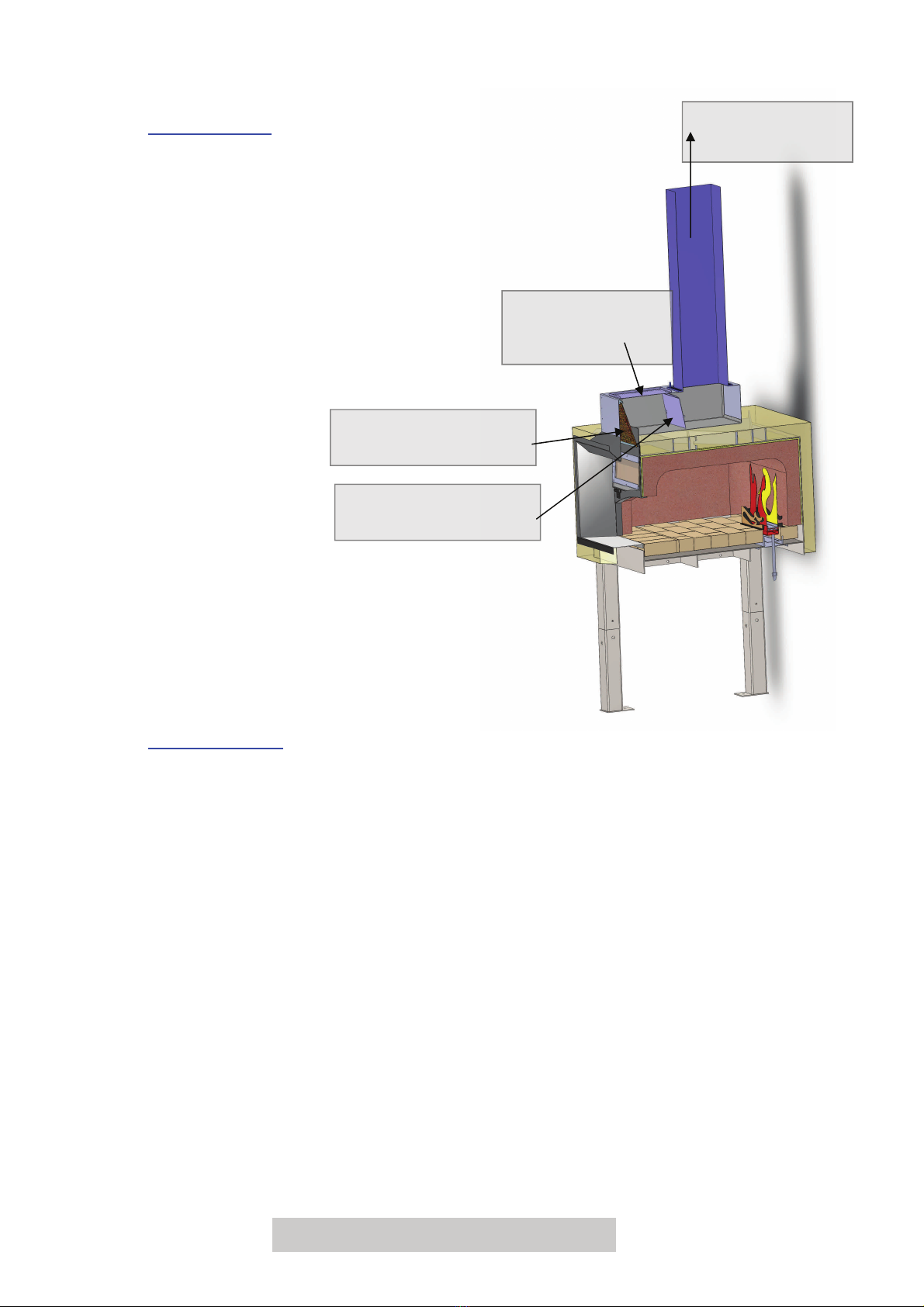
5. Check that the exhaust filter is correctly positioned above the oven door
inside the flue canopy area.
6. Connect to reticulated gas supply at the 19mm (¾”) flare fitting to the isolation
valve fitted to the oven leg.
7. Connect isolation valve to SIT control using braided 3/4” hose supplied.
8. Check all gas / mechanical and electrical connections to all equipment.
9. Ensure burner is located firmly.
10. Check gas flow logic - opening all relevant manual valves.
11. Check the adjustment of the “primary air regulator” on the inspirator connected
to the base of the burner. Initial setting should be about half way between
fully open and fully closed.
12. After the “warm up period” set out in Commissiong section below, this primary
air should be adjusted to achieve clear burning flame in the oven.
On NG it should be blue at the base with light yellow tails,
On Propane, the flame will be mostly light yellow. Deep yellow to orange is NOT
correct and will deposit soot on the roof of the oven.
There must be adequate ventilation beneath the oven to feed air to the gas flame.
The gas control system comes fitted with a standard plug for a wall socket. (Always
unplug the system while any work or inspection is carried out.)
Test operation of the exhaust flue system. This must be fully operational before any
fire can be ignited inside the oven. The exhaust is often connected to the oven
operation by an interlock system. Check with exhaust installers to be sure of operation
procedure.
NOTE: There may be a damper in the flue that may need adjusting. The flue suction
should be adjusted to ~600l/s (1300cfm) however it should be sufficient to not allow
smoke into the kitchen during normal operation.
Proceed with start up procedure outlined in ’Commissioning’
CONNECTION OF GAS SYSTEM

PHOENIX OVENS Installation & Operation Manual 18
SYSTEM OPERATION & DESIGN
With the gas, electricity and exhaust system connected as described earlier the oven
system can be started simply by pressing the “Control” button (#1).
The set value temperature can then be adjusted to control the oven temperature.
FIRST FIRING: If this is the first time that the oven has been fired it is very important to
warm the oven slowly for several days. If the oven is operated at full power at this
time, damage will occur to the refractory lining. The refractory must dry out slowly
during the initial warm up.
To control the power of the initial warm up fire, use the isolation tap below the oven to
set the flame height to a maximum of 70mm. This setting can be left for the first two
days of firing.
SCHEDULE: Day ONE: SV setting at 80°C (175°F).
Day TWO: SV setting at 180°C (350°F ).
Day THREE: SV setting at 250°C (480°F ).
After day three recommended operating temperature is approx 275–315°C (525-600°F)
PREHEAT FIRING
This is best done with the gas system as outlined in the COMMISSIONING section. If gas
is not available:
USING WOOD
The oven must be preheated to thoroughly warm the oven without the purpose of
cooking. This is best done by making a fire just as you would build any fire for a bbq.
NOTE: Take care not over fire. If flame spills out of the oven opening, you are over firing.
A small fire is ideal for slow preheating. Normally 2 or 3 logs of timber are sufficient.
The best wood to use is a HARD, DRY AND DENSE TYPE OF WOOD. DO NOT USE
ANY WOOD THAT HAS BEEN PAINTED OR CHEMICALLY TREATED.
To start the fire, find a flattened cardboard box. Place your larger pieces of hardwood on
the outer extremities of the box and place kindling and softwood on the inside with
newspaper under the kindling. Light the kindling.
Once the kindling is satisfactorily alight, push the whole lot to the position in the oven
(either the side or the back) where you normally locate the fire.
This fire of approximately 16” (400mm) diameter should be kept going for 3 DAYS to
thoroughly pre-heat the oven prior to use.
COMMISSIONING

PHOENIX OVENS Installation & Operation Manual 19
SECTION 2
OVEN OPERATION

PHOENIX OVENS Installation & Operation Manual 20
If you are having any problems, please to call the Phoenix office or the local
representative.
The PHOENIX OVEN only requires wood for satisfactory operation. Some models have
the extra facility of a gas burner for those clients that are looking for a more automated
cooking system.
The oven cavity is basically self-cleaning. A brush and scraper can be used to sweep
debris and food waster from the floor of the oven. A damp mop can be used to wipe the
oven floor area to clear ash debris. Do Not use a very wet mop as this will wear and/or
damage the mantle surface.
The roof and wall area of the oven is self-cleaning by the oven temperature which should
exceed 420°C (790°F ) from time to time during warm-up periods. If discoloration or
contamination should appear, firing the oven to a high temperature for a couple of hours
should restore these areas to a clean finish.
FIRING UP TO COOK USING WOOD
As per the preheat guide (p.14):
1. Start a small fire in the mouth of the oven with kindling (placed on folded cardboard)
and proceed making the fire with larger timbers.
2. Once you have the large timber eg.100-125mm (4-5”) diameters, burning, push the
fire to the back or side of the oven.
3. From cold, allow the oven approximately 3 hours to heat up initially. Thereafter,
warm up should take about 60 minutes. Using gas can reduce this time.
NOTE: Once the oven has been operated daily, the oven will be hot on arrival in the
morning and may take as little as one hour to reheat.
The oven temperature is basically controlled by the size of the fire or the ’set point’ of the
gas system and the draft up into the flue system.
In all circumstances it is recommended that cooking is not attempted until the oven has
reached a temperature of 175°C (350°F ).
Optimum temperature for pizzas is approx. 350°C (660°F ). If there is no temp gauge
installed, once the oven has been preheated and has been heated to cooking
temperature the oven will reheat in about one hour. If pizzas do not cook in around five
minutes, either the oven is too cool (a larger fire required) or you need to adjust the
damper in the flue.
The pizzas should be rotated to suit their cooked condition. The chef soon becomes
familiar with the radiated and reflected heat conditions in the oven and moves his pizzas
around to suit this. Most restaurants place the dough directly on the brick although they
OPERATION OF OVEN & COOKING
Table of contents