Introduction
1Introduction
1.1 Model Survey
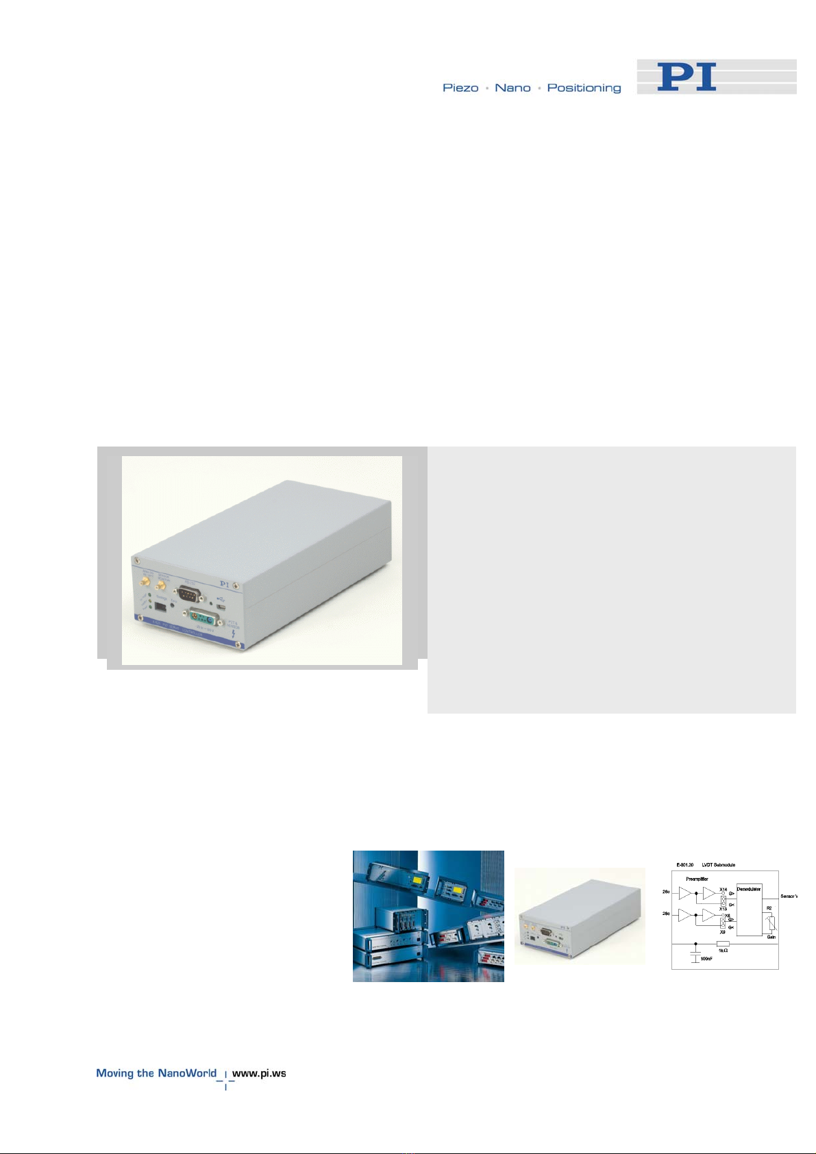
The E-625 amplifier/controller is a stand-alone desktop device
designed to drive and control the displacement of a low-voltage
piezoelectric stage or actuator (LVPZT). The following models
are described in this manual; each supporting a different
position-sensor type:
E-625.LR LVPZT controller, provides AC sensor
processing for usage with LVDT sensors
(equipped with E-801.2x sensor submodule)
E-625.SR LVPZT controller, provides DC sensor
processing for usage with strain gauge sensors
(SGS; equipped with 801.1x sensor submodule)
Both models come with an E-802 Servo-Controller and an E-
816 Computer Interface and Command Interpreter installed as
standard.
Networking of E-625’s with each other allows controlling up to
12 devices over a single RS-232 or USB computer interface.
Networking requires additional wiring and setup.
E-625s for use with capacitive sensors are described in detail in
their own manual, PZ166. The E-625.C0 is the same as the E-
625.CR, except that it has the analog control interface only. It is
described in User Manual PZ187.
1.2 Prescribed Use
Based on their design and realization, the E-625 LVPZT
Controller/Amplifier is intended to drive capacitive loads, in the
present case, piezoceramic actuators. The E-625 must not be
used for applications other than stated in this manual,
especially not for driving ohmic (resistive) or inductive loads.
E-625s can be operated in closed-loop mode using position
sensors. The type of position sensor used must be compatible
with the E-625 model to which it is attached: in particular linear
variable differential transformers (LVDT) require the AC
excitation provided by the E-625.LR, and strain gauge sensors
(SGS) require DC exitation provided by the E-625.SR.
www.pi.ws E-625 PZ167E Release 1.4.0 Page 3