PHYWE Cobra SMARTsense User manual

1
www.phywe.com, © All rights reserved 12946-00 / 3520
Operating
instructions
Cobra SMARTsense Weatherstation
12946-00
PHYWE Systems GmbH & Co. KG
Robert-Bosch width 10
D-37079 Göttingen
Phone +49 (0) 551 604-0
Fax +49 (0) 551 604–107
Internet www.phywe.de
The unit complies
with the applicable
EC-guidelines
directives
Fig. 1: 12946-00 Cobra SMARTsense Weatherstation
TABLE OF CONTENTS
1SAFETY PRECAUTIONS
2PURPOSE AND CHARACTERISTICS
3FUNCTIONAL AND OPERATING ELEMENTS
4NOTES ON OPERATION
5 HANDLING
6TECHNICAL DATA
7SCOPE OF DELIVERY
8ACCESSORIES
9 CONFORMITY
10 DISPOSAL
1 SAFETY PRECAUTIONS
Carefully read these operating instructions completely
before operating this instrument. This is necessary to
avoid damage to it, as well as for user-safety.
Only use the instrument for the purpose for which it was
designed.
Protect the instrument from dust, moisture and vapours.
Use a slightly moist lint-free cloth to clean the instrument.
Do not use aggressive cleaning agents or solvents.
Do not open the unit.
2 PURPOSE AND CHARACTERISTICS
The sensor measures wind speed, wind direction, barometric
pressure, humidity, dew point, wind chill temperature, ambi-
ent temperature, ambient light, UV index, PAR and irradi-
ance. The GPS module reports latitude, longitude, altitude,
speed and direction.
The measured values can be read off the display or transmit-
ted via Bluetooth or USB to any end device such as tablets,
smartphones, etc.
An offline measurement with subsequent evaluation of the
measured data on a terminal device is also possible.
Caution!

2
www.phywe.com, © All rights reserved 12946-00 / 3520
3 FUNCTIONAL AND OPERATING ELEMENTS
3.1 Operating elements
The sensor has a power button, two arrow keys for naviga-
tion and 2 LEDs whose function is described below.
Function of the power button
Short press
Switch on the device
Long actuation (> 3s)
Switch on Bluetooth
Switch off the device
Warning: To switch off the device, Bluetooth must be
switched on.
Function of the button
Short
press
Select vertical menu.
(headings)
>3s
actuated
Language configurati-
on
Fig. 2
Function of the button
Short press
Select horizontal menu.
(measurement channels)
Long actuation (>3s)
In category weather and
light
Wind direction calibration
Long actuation (>3s)
In section GPS
Switching GPS on / off
Functions of the Bluetooth LED
Flashes red every 2s
Not connected
Flashing green every
2s
Connected to terminal de-
vice
Flashing green every
4s
Measurement recording in
progress
Functions of the charging LED
Flashing red
Low battery
Red luminous
Charging active
Green shining
Charging finished
3.2 Functional elements
Fig. 3
3.3 USB port
The battery, which is permanently installed in the sensor, is
charged via the type C USB port. Furthermore, communica-
tion with a computer takes place via this interface.
To prevent moisture from penetrating, press the rubber cover
onto the USB socket.
3.4 Wind sensor impeller
Position the impeller in the wind so that it is blown at a right
angle, or press the unit onto the rotating head of the stand
and mount the wind vane. The unit will now automatically po-
sition itself in the wind.
3.5 Wind vane
The supplied wind vane is screwed into the thread in the
middle of the back and secured with the union nut. The wind
vane automatically turns the unit into the wind when it is
rotatably mounted, for example on a tripod.
3.6 Light sensor
The light sensor is mounted on the top of the unit, protected
from water. Align the sensor according to the light source.
3.7 Tripod connection
Press the black cap on the bottom of
the sensor onto the rotatable adapter
on the stand.
Fig. 4
4 NOTES ON OPERATION
This device fulfils all of the technical requirements that are
compiled in current EC guidelines. The characteristics of this
product qualify it for the CE mark.
The individual connecting leads are each not to be longer
than 2 m.
The instrument can be so influenced by electrostatic charges
and other electromagnetic phenomena (HF, bursts, indirect
lightning discharges) that it no longer works within the given
specifications. Carry out the following measures to reduce or
eliminate the effect of such disturbance: Ensure potential
equalization at the PC (especially with Laptops). Use screen-
ing.
5 HANDLING
This section describes the start-up of the sensor and the re-
cording of measurement data. Please read this section thor-
oughly in order to avoid failures or operating errors.
5.1 Charging process
Connect the sensor to a computer or an appropriate USB
charger (not supplied) using a USB-C connection cable.
During charging, the charging LED lights up red. When the
charging process is complete, the charging LED lights up
green. The charging time for an empty battery is a maximum
of 3 hours.
Light sensor
Wind sensor
Impeller
Wind vane
Tripod
connection
USB

3
www.phywe.com, © All rights reserved 12946-00 / 3520
Disconnect the charger at the latest four hours af-
ter the completion of the charging process. Other-
wise, the service life of the battery may be nega-
tively affected.
5.2 Start-up
5.2.1 Use without software / APP
After briefly pressing the power button , the
Display open. All relevant measured values can now be dis-
played via two symbol menu bars. The selection is made via
the arrow keys.
Measurement channels
Selection via the key
Fig. 5
Categories :
Selection via the key
Category Weather data
Wind speed:
The wind speed is determined from the rotation speed of the
anemometer. It is important to ensure that the air can flow
directly into the turbine. The wind speed must be at least 0.5
m/s to be measured.
Wind direction:
An electronic compass determines the wind direction in the
range of 0...360°. N = 0°/360°, E = 90°, S = 180°, W = 270°.
To calibrate the electronic compass, press the key for at
least 3 seconds. The display switches over (see fig.6 and
fig.7). Now turn the sensor 3-4x in horizontal and 3-4x in ver-
tical direction. The direction of rotation can be seen on the
display.
Fig.6 horizontal calibration Fig.7 vertical calibration
Ambient temperature:
The outside temperature is measured at the unit. To obtain
accurate readings, the unit must not be exposed to sunlight.
Relative humidity:
The relative humidity indicates the saturation ratio of the air,
taking into account the temperature, in percent (%). An air
humidity of 100% means that the air is maximally saturated
Absolute humidity:
The absolute humidity indicates how many grams (g) of water
are contained per cubic metre (m³) of air (water vapour densi-
ty).
Dew point:
The dew point indicates the temperature to which air must be
cooled until it is saturated with water vapour so that it can
start to condense.
The following figure shows the dew point as a function of rel-
ative humidity for different temperatures:
Fig. 8 : Dew point for 4 different temperatures
Wind Chill
The Wind Chill (also called wind chill or wind chill)
describes the difference between the measured ambient
temperature and the perceived temperature as a function of
wind speed. It is defined for temperatures below 10°C, be-
cause from this temperature on the absolute humidity of the
air is less than 1% to the air mass, and therefore its influence
on the thermal conductivity and heat capacity is negligible.
5 °C
3 °C
1 °C
0 °C
-1 °C
10 km/h
2,3
0,1
-2,1
-3,2
-4,3
15 km/h
-0,6
-3,0
-5,4
-6,6
-7,8
20 km/h
-2,9
-5,4
-8,0
-9,3
-10,6
25 km/h
-4,6
-7,3
-10,0
-11,3
-12,7
30 km/h
-6,0
-8,8
-11,6
-13,0
-14,4
Fig. 9: Wind Chill in the range -1...5°C and 10...30 km/h
Barometric pressure
The pressure corresponds to the weight of the column of air
standing on a body on the surface of the earth. The meas-
ured pressure value corresponds to the actual ambient pres-
sure, not the sea level-corrected pressure.
Category Lighting data
Ambient light
Ambient light is detected by the light sensor installed in the
top of the housing.
Fig. 10
Attention: For correct measurement, it is important to ensure
that the light sensor is free of dirt and that there are no water
droplets in front of the light sensor.
Light sensor

4
www.phywe.com, © All rights reserved 12946-00 / 3520
UV Index
The UV index is an internationally standardised measure of
the solar irradiance (UV radiation) effective for sunburn.
UV Index
Evaluation
0-2
low
3-5
moderate
6-7
high
8-10
very high
>10
extreme
PAR (Photosynthetically Active Radiation)
The wavelength range of the PAR value is 400-700nm, and
thus largely covers the range of radiation visible to humans
from 380-780nm. This light spectrum is mainly used in organ-
isms for photosynthesis. The PAR value is measured in
µmol/m2/s.
Irradiance
Irradiance describes the total power of incoming electromag-
netic energy striking a surface - in relation to the size of the
area. It is measured in W/m2.
Category GPS (Global Positioning System)
In order to get the longest possible battery life, the GPS func-
tionality is deactivated when the weather station is switched
on.
Press and hold the key for more than 3s to enable and
disable GPS. (Make sure they are in the GPS section, other-
wise the wind direction calibration will be activated).
For position recognition with GPS, at least 3 satellites must
be recognised. The detection can take 1-2 minutes for
weather conditions and satellite positions.
Attention: Reliable detection is only possible outside
buildings.
Height
GPS elevations are based on an ellipsoid (a mathematical
representation of the shape of the earth), while map elevation
data is based on a vertical zero point associated with the ge-
oid (commonly known as sea level). GPS elevation may be
subject to a high degree of deviation due to the varying num-
ber of satellites detected for horizontal position detection (e.g.
hidden by the earth).
Latitude
The geographical latitude is given as the angle between the
line earth-centre-equator and the line earth-centre-place.
North and south pole have a latitude angle of 90°. In order to
distinguish places in the northern hemisphere from those in
the southern hemisphere, the latitude is also given an N for
north or an S for south in the traditional notation.
Longitude
The longitude is given as the angle between the line Earth
Centre - Zero Meridian and the line Earth Centre - Location.
The Greenwich meridian has an angle of 0°, while the oppo-
site longitude, along which the dateline runs, has an angle of
180°.
The prime meridian divides the earth's surface into a western
and an eastern hemisphere. In order to distinguish places on
the two hemispheres from each other, the traditional notation
additionally gives the longitude a W for west or an E for east.
The latitude and longitude are given in sexagesimal system.
This is based on the number 60, where the coordinates con-
sist of 3 components.
1. Longitude and latitude are given as angles (°).
2. Each degree has 60 minutes. These are indicated
by a prime (′).
3. Each minute has 60 seconds, which can be identi-
fied by a double prime (″).
Speed
The GPS speed can be determined by using the Doppler ef-
fect. This describes the extent to which a radio signal is com-
pressed or stretched when it is transmitted by an object in
motion. The speed results from the frequency change ∆f, the
signal frequency f and the speed of light c: v = ∆f c / f / 2.
The absolute accuracy is about 0.1 km/h.
True direction.
The True Direction refers to the true north pole (or Geograph-
ic North Pole), which differs from the magnetic north pole by
a few degrees. The direction is shown in °.
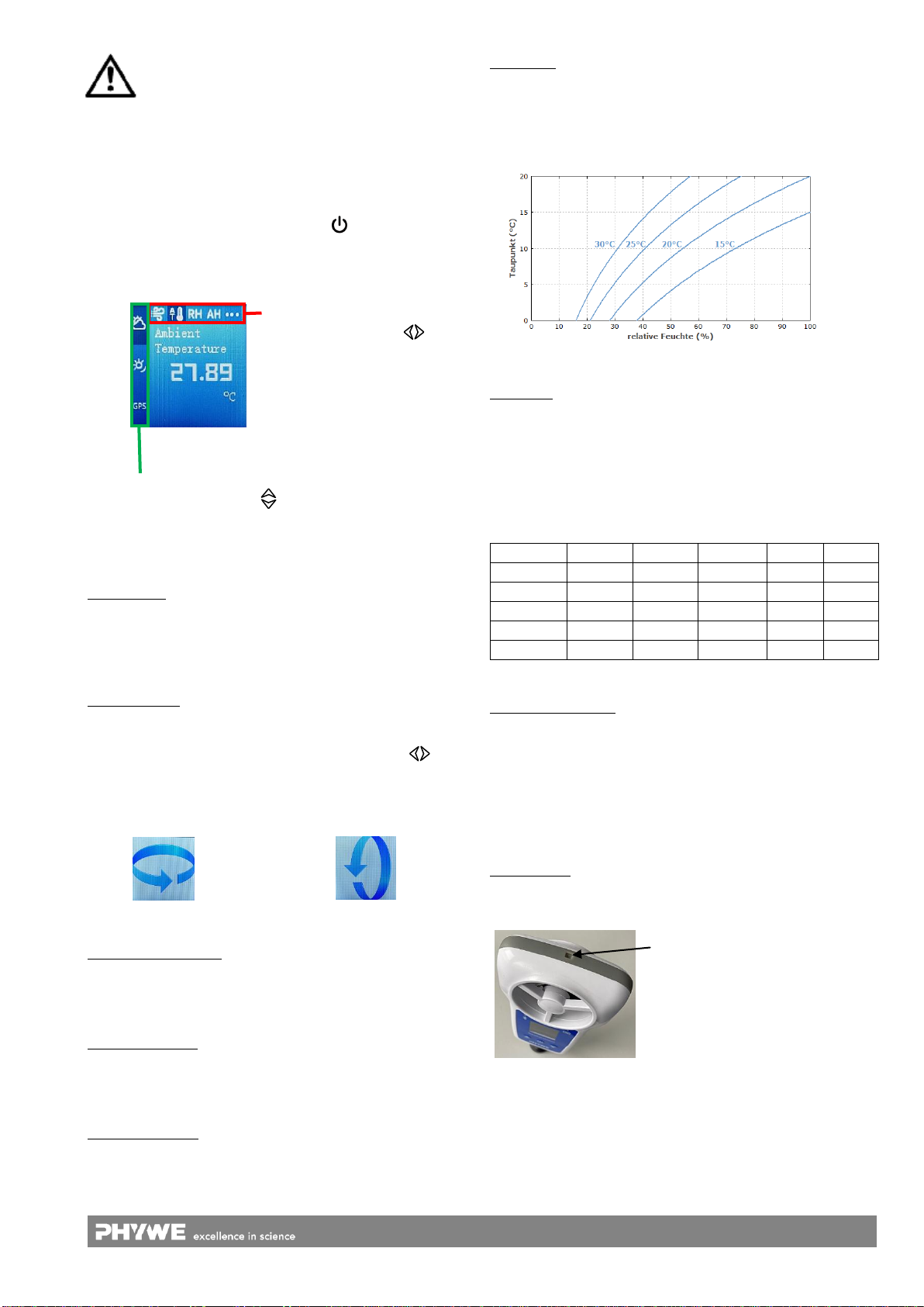
Starting an offline measurement recording
To start a measurement, press the power
button three times in quick succession.
Afterwards the Bluetooth LED flashes
green 3 times in quick succession, con-
firming the successful start. To stop a
measurement press the power button
twice in quick succession. The green LED
also acknowledges this.
Measurement stopped
Measurement started
Even during a started measurement, the display switches off
after 5 minutes if no more keys are pressed. A flashing Blue-
tooth LED indicates that the measurement is still running.
With the PHYWE measuring software the measured data can
be read out later via Bluetooth or USB.
Attention: Bluetooth cannot be activated during an ongo-
ing offline measurement.
Language settings
To change the language, press the button for longer than
3s. Now you can select the appropriate language with the
push-button . To confirm the selection, press the button
again for more than 3s.
Use with software / APP
Switch on the sensor by pressing and holding the power but-
ton for more than 3s. Now the Bluetooth LED flashes red.
Start the software and select the sensor.
If the sensor is to be used via the USB interface, it does not
need to be switched on. The sensor is connected directly to
the terminal device using the supplied USB cable.

5
www.phywe.com, © All rights reserved 12946-00 / 3520
A 9-digit code is print-
ed on the back of the
sensor (Fig.11). The
last 4 digits of the code
are displayed as sen-
sor designation in the
software (fig.12). This
allows an exact as-
signment of the sen-
sors
possible with the soft-
ware. Fig. 11
Fig. 12
Make sure that the Bluetooth interface is activated on the
terminal device (PC/Tablet/Smartphone) and that the soft-
ware is allowed to access the interface.
After the sensor has been selected in the software, the LED
flashes green to indicate that the connection has been estab-
lished correctly. After the sensor has been coupled with the
software, the sensor is no longer visible to other users in the
software, and therefore can no longer be selected.
If the sensor is switched on and not connected, it switches off
automatically after 5 minutes.
6 TECHNICAL DATA
Operating temperature range: 5 - 40°C
Relative humidity < 80%.
Wind speed:
Measuring range
Resolution
Wind direction:
Measuring range
ambient temperature:
Measuring range
Resolution
Relative air humidity
Measuring range
Resolution
Absolute humidity
Measuring range
Dew point
Measuring range
Wind Chill
Measuring range
Barometric pressure
Measuring range
Resolution
Ambient light
Measuring range
Resolution
UV Index
Measuring range
Resolution
PAR
Measuring range
1.8...54 km/h
0.36 km/h
0…360 °
-40…125 °C
0.1 °C
0…100 %
0.1 %
0...600 g/m3
-10…40 °C
-70…10 °C
450...1100 hPa
0.2 hPa
0...128000 Lx
1 Lx
1…12
1
0...2400 µmol/m2/s
Radiant intensity
Measuring range
Height
Measuring range
Longitude/Latitude
Measuring range
Speed
Measuring range
True direction
Measuring range
0...1362 W/m2
0…18000m
0…180°
0...1854 km/h
0…360°
Max. data rate
Battery capacity
Max. radio range (free field)
Protection class
10 Hz
1000 mAh
30 m
IP67
Dimensions (LxWxH)
80 x 170 x 38 mm
Mass
161 g
7 SCOPE OF DELIVERY
The extent of delivery is as follows
Cobra SMART Weatherstation 12946-00
USB connection cable type C 07935-00
Wind vane
Tripod (incl. bag)
Operating instructions
8 ACCESSORIES
The following accessories are available:
USB-Charger 07934-99
USB-Bluetooth-Adapter 07936-00
Software measureLAB 14580-61
Free measureApp available from supplier portals
iOS
Android
9 CONFORMITY
PHYWE Systeme GmbH & Co.KG hereby
declares that the radio system type 12946-
00 complies with the 2014/53/EU directive.
The complete text of the EC Declaration of
Conformity is available at the following
internet address:
www.phywe.com/en/ec-declaration

6
www.phywe.com, © All rights reserved 12946-00 / 3520
10 DISPOSAL
The packaging mainly consists of environmentally-friendly
materials that should be returned to the local recycling sta-
tions.
PHYWE Systeme GmbH & Co. KG
Abteilung Kundendienst
Robert-Bosch-Breite 10
D–37079 Göttingen
Telefon +49 (0) 551 604-274
Fax +49 (0) 551 604-246
Do not dispose of this product with normal
household waste. If this unit needs to be
disposed of, please return it to the address
that is stated below for proper disposal
Table of contents
Popular Weather Station manuals by other brands

La Crosse Technology
La Crosse Technology C84428 user manual

LEXIBOOK
LEXIBOOK Meteoclock SM880 owner's manual

Auriol
Auriol 415894 2210 Assembly, operating and safety instructions

Columbia Weather Systems
Columbia Weather Systems Magellan 420 user manual

Auriol
Auriol AHFL 433 B2 user manual

Oregon Scientific
Oregon Scientific Weather Home RAR213HGX manual