Safety Precautions
1Safety Precautions
WARNING
Failure to heed warnings in this manual can result in bodily
injury or material damage. Note that E-650
Controller/Amplifier do not contain any user-serviceable
parts.
!
CAUTION
The E-650.OE Amplifier PCB is an ESD-sensitive
(electrostatic discharge sensitive) device. Observe all
precautions against static charge buildup before handling
these device.
Avoid touching circuit components, pins and PCB traces.
Discharge any static charge you may have on your body by
briefly touching a conductive, grounded object before you
touch any electronic assembly. Pose PCBs only on
conductive surfaces, such as ESD-safe transport
containers (envelopes, foam). Electronic subassemblies
must always be kept and transported/shipped in conductive
packaging.
Make sure that no conductive particles of any kind (metallic
dust or shavings, broken pencil leads, loose screws)
contact the device circuitry.
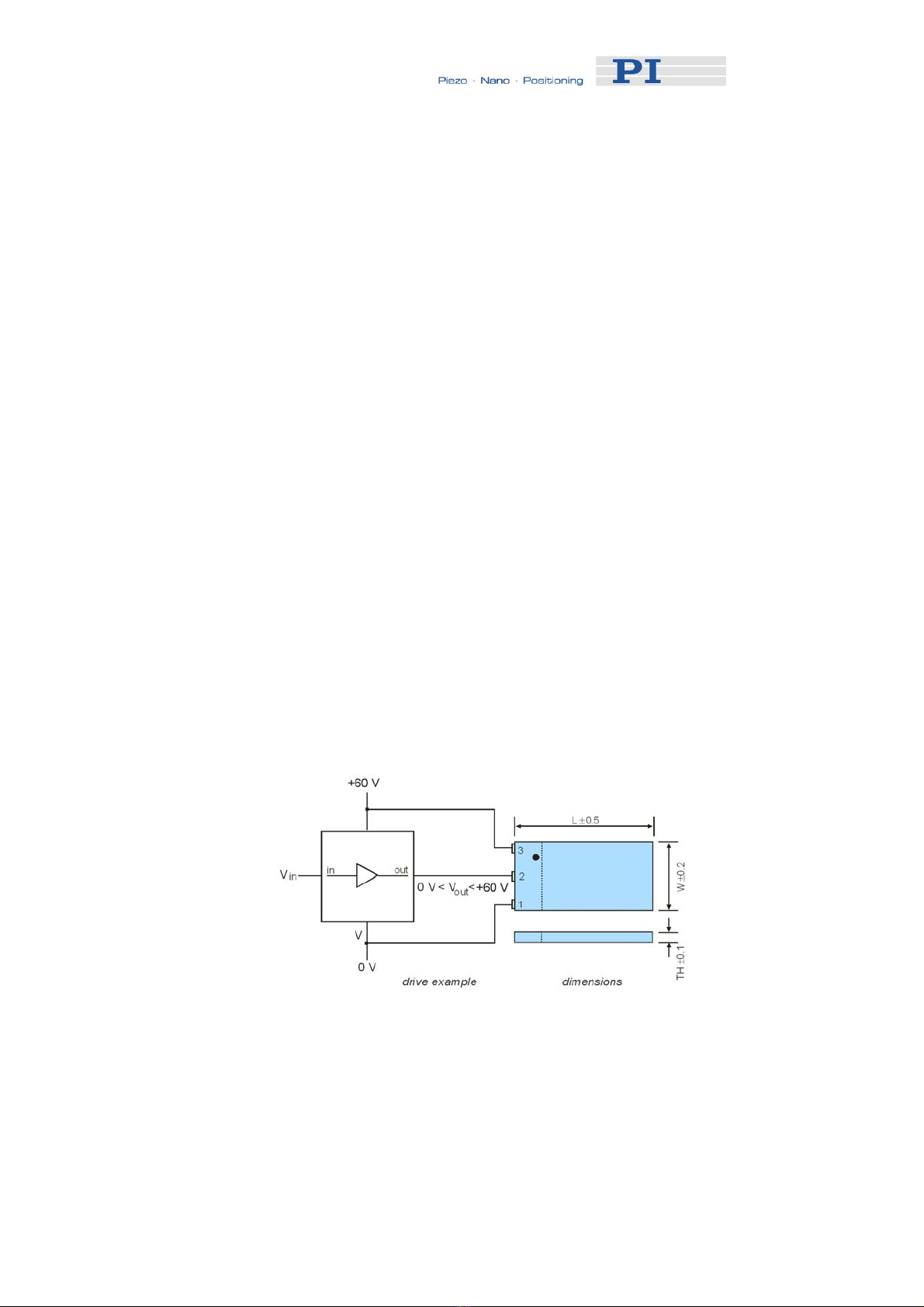
DANGER
E-650s are amplifiers generating high voltages of up to
60 V for driving piezo actuators. The output power may
cause serious injuries.
Working with these devices or using piezoelectric products
from other manufacturers we strictly advise you to follow
the General Accident Prevention Regulations.
All work done with and on the devices described here
requires adequate knowledge of handling high voltages.
www.pi.ws E-650 LVPZT Amplifier PZ 97E Release 1.0.3 Page 2