PI P192-S User manual

2Pi P192-S Telemetry Radio Application Note
Pi P192-S Telemetry Radio
Application Note

3
Disclaimer
Pi Research makes no representation or warranties of any kind whatsoever with respect
to the contents hereof and specifically disclaims any implied warranties of merchantability
or fitness for any particular purpose. Pi Research shall not be liable for any errors
contained herein or for incidental or consequential damages in connection with the
furnishing, performance or use of the software, associated hardware, or this written
material.
Pi Research reserves the right to revise this publication from time to time, and to make
changes in the content hereof without obligation to notify any person of such revision or
changes.
A copy of the Pi Research Terms and Conditions of Sale is available on request, and
includes a declaration of the warranty and limitation of liability which apply to
all Pi Research products and services.
Health and Safety information
Under the terms of European and UK Health and Safety Legislation, Pi Research is
required to classify any hazardous materials in the products it supplies and to provide
relevant safety information to users.
Any hazardous materials in Pi products are clearly marked with appropriate symbols.
Product Safety Data Sheets relating to these materials are available on request.

4Pi P192-S Telemetry Radio Application Note
Introduction .............................................................................................. 6
Licensing information ..................................................................... 6
Car radio installation ............................................................................... 7
Installing a P192-S radio in a car ................................................... 7
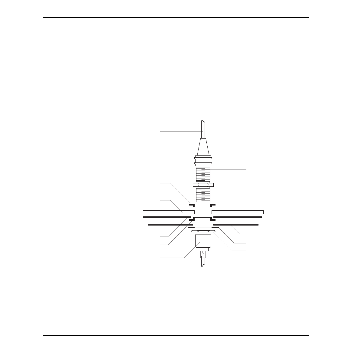
Car radio transmit antenna ............................................................. 8
P192-S as a pit receiver......................................................................... 11
Power supply ................................................................................ 11
Pit data loom ................................................................................. 11
Diversity receiving function .......................................................... 12
Pit receiver antenna ..................................................................... 13
Connecting antennas ............................................................................ 14
Configuring the P192-S ......................................................................... 15
Radio configuration utility ............................................................. 15
P192-S status LED’s .............................................................................. 20
Serial Interface ....................................................................................... 21
Baud rate setting .......................................................................... 21
Forward error correction (FEC) .................................................... 21
Pi Sigma stream optimization ....................................................... 22
Minimisation of the Message Size ................................................ 23
Transmit buffer ....................................................................................... 24
CTS (Clear to send) ............................................................................... 25
Specifications ......................................................................................... 26
Connector information .......................................................................... 27
Connector details .......................................................................... 27
Data connector pin details ............................................................ 27
Contents

5
Parts numbering .................................................................................... 28
Dimensions ............................................................................................. 29
Declaration of conformity ..................................................................... 30
Conditions Of Use ........................................................................ 31
FCC Authorisation ........................................................................ 31
Contact information ............................................................................... 32

6Pi P192-S Telemetry Radio Application Note
Introduction
The Pi telemetry system provides reliable data transmission from a car to the pits as the
car travels around the track. A P192-S radio in the car transmits the telemetry data and a
P192-S radio in the pits receives the transmissions. The received telemetry data is passed
to a PC for processing and display.
The P192-S radio has no user controls and the setup is carried out by Pi Research. The
frequency and transmit power can be programmed via the Pi Programming software with
the programming lead connected in line with the radio and to a PC’s comm port.
Licensing information
Before you use the telemetry system you must apply to the appropriate radio licensing
authority for the frequency and power setting that you intend to use.

7
Car radio installation
Installing a P192-S
radio in a car
The P192-S radio needs a power supply between 12 to 30 volts DC. If you are connecting
the telemetry system to a Pi System, the radio loom connects battery power to the radio
system.
If you are building your own wiring loom for the telemetry system refer to the section
Connector information
.
CAUTION: The anti-vibration mounts supplied MUST BE used to mount the radio.
The radio will not function correctly, may be damaged, and its warranty will be
void if the anti-vibrations mounts are not used.
When installing the P192-S radio in a car:
■the anti-vibration mounts supplied MUST BE used to mount the radio. The
radio will not function correctly if the anti-vibration mounts are not used;
■select a position where the radio will not be in constant contact with water,
fuel or oil;
■make sure that the radio will not be affected by heat soak. Ensure that air
can flow over the radio to keep it below 55°C; Insufficient airflow will
overheat the transmitter, and the radio will shut down until the temperature
drops sufficiently.
■make sure that the radio is electrically isolated from the chassis and all
surrounding parts;
■ensure connector casing is isolated from all loom connections and the loom
screen;
■try not to place the radio near sources of electrical interference e.g. ignition
coils, plug leads, ECMs, alternators and other radio transmitters.

8Pi P192-S Telemetry Radio Application Note
Data loom
When installing the data loom, you should avoid running it next to sources of interference,
i.e. ignition coils, plug leads, alternators, fuel pumps and ECMs. If the loom has to run near
any of these, then try to avoid parallel runs.
Car radio transmit
antenna
Ground planes
The transmit antenna needs a suitable ground plane to operate efficiently. The ground
plane is a conductive material placed at the base of the antenna and increases the
efficiency of the antenna by reducing the amount of power that is reflected back into the
radio module.
Generally, the construction and shape of a race car does not allow for a suitable ground
plane. To use your telemetry equipment effectively, you may have to make a suitable
ground plane.
Each antenna comes with an installation kit that includes a piece of self-adhesive copper
foil which you can use to make a ground plane.
When making a ground plane, you should consider the following points:
■The antenna should be mounted in a vertical position in the centre of the
ground plane and at least 150mm (6 inches) away from any vertical piece
of the car or other antenna;
■The ground plane should be circular and have a radius at least equal to the
length of the antenna;
■The ground plane must not make electrical contact with any part of the
vehicle chassis that is likely to conduct, for example, carbon fibre.

9
Fibre glass body panels
To fit the antenna to a fibre glass body panel:
1Locate a suitable panel, that can be removed easily for access to the antenna
loom.
2As fibre glass is electrically non-conducting, you can stick the copper foil
directly to the underside of the panel.
3Tighten the TNC connector of the antenna, ensuring that it makes electrical
contact with the copper foil.
4Ensure that the copper foil does not make contact with any part of the chassis
that is likely to conduct.
Antenna
TNC bulkhead
connector
Insulating layer
Insulating washer
Copper foil
Locking washer
Fixing nut
TNC terminated
feed cable
Body panel
Insulating washer
Antenna installation detail

10 Pi P192-S Telemetry Radio Application Note
Carbon fibre chassis panels
1Locate a suitable panel that can be removed easily for access to the antenna
loom. An ideal panel is over the front suspension dampers.
2Make a bracket from metal or carbon fibre that will hold the antenna vertical.
Fix the bracket to the chassis.
3Stick an insulating layer of ‘tank tape’ to the underside of the bracket. Make
sure that it is of a larger diameter than the copper foil for the ground plane.
4Stick the copper foil to the underside of the insulating layer.
5Tighten the TNC connector of the antenna, ensuring that it makes electrical
contact with the copper foil.
6Ensure that the copper foil does not make contact with any part of the chassis
that is likely to conduct.
7Drill a hole in the panel for the antenna to pass through.
Antenna feed loom
If you are going to use your own antenna feed loom, it should be a high quality coaxial
cable, with a stranded inner core. We recommend that you use RG58 50 ohm coaxial
cable.
For best results, use crimp TNC connectors for both the radio and antenna ends of the
feed cable.
WARNING: It is important that the TNC connectors of the feed loom do not vibrate
against any other conducting surfaces such as Lemo connectors or the chassis
floor, as this will result in radio frequency noise and a loss of signal.

11
P192-S as a pit receiver
The P192-S radio can be used in a car as a radio transmitter or in the pit as a radio
receiver. The pit car transmitter frequency and the pit receiver frequency must be the
same. Refer to the section
Configuring the P192-S
for information.
Power supply
Use the power supply provided to run the P192-S in the pit.
Pit data loom
The pit data loom connects the telemetry pit receiver to your PC. The computer connector
is a standard RS232 9-pin D-type connector and should be connected to a serial port of
your PC.
If your PC has more than one serial port, then refer to the documentation that came with
your PC to find out how the serial ports are labelled. You can only connect the telemetry
data loom to either serial port COM1 or COM2 of your PC.
You must use Pi Workshop software to set which ports of your computer are used for
telemetry, before you attempt to use the telemetry system.

12 Pi P192-S Telemetry Radio Application Note
Diversity receiving
function
Where line-of-sight does not exist between car and pit antennas, received signals
propagate as reflections. Reflected signal paths can destructively interfere with each other.
This effect is called Multi-Path Fading.
An Anti-Node is a point in space where Multi-Path Fading diminishes Signal Strength
Received signal - dB
Time
signal threshold
level
Quality is checked every 1 or 12 bytes
Two fades are unlikely to occur at the same time
Representation of multi-path fading
The Diversity Receiving Function of the of the P192-S means that when receiving, the
P192-S actively monitors the strongest signal from it’s two receiving antennas. It is unlikely
that an Anti-Node will occur simultaneously at both antennas, hence superior coverage
can be achieved when compared to a non-Diversity Receiving radio.

13
Pit receiver antenna
To ensure that the two pit antennas are not affected simultaneously by the same Anti-
node, their closest points must not be closer than 0.75 metres (3/4 wavelength).
For the best circuit coverage, the pit antennas need to be as high as possible. The pit
antennas should be mounted at least 2 metres away from any other transmitting antenna.
The antennas should be connected to the P192-S pit unit by low loss coaxial cables,
Pi Research Part Number 03I-0566-variant (variant refers to the loom length, which can
be specified at the time of order).
If you mount two antennas on a single mast, you should mount them as far away from
each other as is possible.
Antenna feed looms
If you are going to use your own antenna feed loom, it should be of high quality coaxial
cable, with a stranded inner core.The type of cable is determined by the proposed length
of the feed loom.
■For antenna feed looms of less than 10 metres (33 feet) in length use
URM43 coaxial cable.
■For antenna feed looms greater than 10 metres (33 feet) in length use
URM67 coaxial cable.
For best results, use crimp TNC connectors for the radio and solder N type for the antenna
end of the feed cable. The connectors must be kept watertight, and we recommend that
you wrap them with self-amalgamating tape.

14 Pi P192-S Telemetry Radio Application Note
Connecting antennas
CAUTION: A P192-S should only be used as a transmitter when a length of
coaxial cable has been attached to the TNC connector NEAREST the AutoSport
connector. If this is not done, the P192-S may damage itself, and its’warranty will
be void.
A P192-S only transmits a radio signal from the TNC connector that is NEAREST the
AutoSport connector. Both TNC connectors of a P192-S will receive radio signals.
P192-S as a transmitter
When a P192-S is used for transmission only, an antenna must be connected to the TNC
connector NEAREST the Autosport connector. See the figure
Connecting antennas
below.
P192-S as a receiver
If a P192-S is to be used for receiving, antennas should be connected to both TNC
connectors to take advantage of the P192-S diversity receiving capability. See the figure
below.
connect antenna
here when radio is
installed in a car
do not connect anything
here when the radio is
installed in a car
connect antennas to both connectors
when radio is installed in the pit
AutoSport
connector
Connecting antennas

15
Configuring the P192-S
Radio configuration
utility
To enable the P192-S to be configured, a software utility application for the PC and a
programming loom are supplied.
The configuration utility application is supplied on a CD-ROM.
To install the configuration utility application:
1Insert the CDROM into the CD drive of the PC. The installation programme
should start automatically.
2Follow the on-screen instructions.
To configure the PI92-S:
1Connect the programming loom as shown in the next figure.
to serial port
on PC
programming loom
telemetry
connector on
loom
P192-S radio
Connecting the programming loom
2Click Start • Programs • Pi Research •P192-S-Config. The P192-S
configuration start-up screen appears.

16 Pi P192-S Telemetry Radio Application Note
P192-S configuration start-up screen
After a short delay the Pi Research P192-S Telemetry Radio Configuration dialog replaces
the P192-S configuration start-up screen.
Pi Research P192-S Telemetry Radio Configuration dialog
You can change the COMM port which the configuration utility connects to.
3Click Comms Port Setting and choose from the list.

17
4Power-up the radio and click Connect. The red bar on the Connect button
changes to green. The dialog also displays the message Reading Radio
settings.
Reading radio settings message
The current Radio Frequency and Transmission Power settings are then displayed in
the text boxes on the dialog.
Radio Frequency Setting
Note: Licensing of the P192-S is the responsibility of the radio’s operator.
Both the car and pit radios must be configured to communicate on the same frequency.
5Enter the required frequency into the Radio Frequency text box.
The radio can be programmed within the range 458 > 460 MHz and the frequency must
be divisible by 25kHz (the radio’s channel spacing).
Radio power setting
Radio Power should be chosen according to longest straight-line distance that the car
travels from the Receive antennas. High power can overcome signal strength fading due
to distance, but not major obstacles, so there is limited coverage to be gained by
increasing power in situations where the transmission distance is comparatively short.
Typical power settings are 1 Watt for ovals and 2 Watts for conventional road courses and
street circuits.
6Choose the required power setting from the list in the Transmission Power
text box.
7Click Set Radio Power and Frequency. The new settings are sent to the
radio.
The Setting up Radio message appears on the dialog.
Setting up Radio message

18 Pi P192-S Telemetry Radio Application Note
This followed by the Saving settings for Radio message being displayed on the dialog
box.
Saving settings for Radio message
After the settings have been saved in the radio, the following message appears.
Run mode Warning message
This message tells you that the radio is now in Run mode. You will have to power cycle
the radio if you want to perform further configuration on that radio.
If you have set a frequency outside of the valid range, the following error message
appears.
Error message: Set valid frequency
If you have set a frequency that is not divisible by 25kHz an error message appears.
25kHz boundary error message

19
Read Existing Radio Settings
Click Read Existing Radio Settings any time after connecting to the radio, to read the
existing settings.
Set Pi Defaults button
It is not recommended to use the Set Pi Defaults button, unless instructed to do so by
Pi Research Support. Use of this feature will disable any custom configuration that may
have been performed by Pi Research.
Cannot connect to radio error message
If you click Connect after setting Radio Power and Frequency, and you have NOT power
cycled the radio, you will get the following error message.
Cannot connect to radio error message
To allow you to Connect to the radio again, you must power cycle the radio.
Radio not detected error message
If you click Read Existing Radio Settings before you have connected to the radio you
will get the following error message.
Radio not detected error message

20 Pi P192-S Telemetry Radio Application Note
P192-S status LED’s
The P192-S has a number of LEDs which indicate the status of the unit. The table below
lists the LEDs and their meaning when the LEDs are on.
LED Colour Meaning
CD Red Transmitting radio signal
Orange Noise on frequency
Green Receiving radio signal
RD Red P192-S sending data via serial port
TD Red P192-S receiving data via serial port
CTS – Not used (hardware handshaking). See note below
RTS – Not used (hardware handshaking)
Note: The P192-S default settings do not have the full CTS line functionality enabled.
This functionality can be enabled upon request by Pi Research.
The figure below shows the location of the LEDs on the P192-S.
Location of P192-S LEDs
Table of contents