July 07, 2023page6
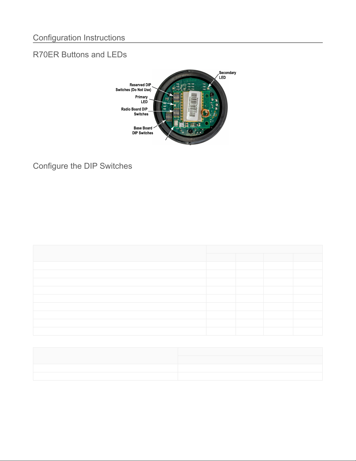
R70ER Ethernet Data Radio
900 MHz Compliance
Radio module is indicated by the product label marking
Contains FCC ID: UE3RM7023: FCC Part 15, Subpart C,
15.247
ContainsIC:7044A-RM7023
2.4 GHz Compliance (SX243 Radio Module)
Radio module is indicated by the product label marking
Contains FCC ID: UE3SX243: FCC Part 15, Subpart C,
15.247
Radio Equipment Directive (RED) 2014/53/EU
ETSI/EN: EN 300 328 V2.2.2 (2019-07) [RED HarmStds]
Contains IC: 7044A-SX243
ANATEL:03737-22-04042
Radio Data Transfer Rate
900 MHz: 300 kbps
2.4 GHz: 250 kbps
Supply Voltage
10 V DC to 30 V DC(Outside the USA: 12 V DC to 24 V DC,
± 10%)
For European applications, power this device from a Limited
PowerSourceasdefinedinEN60950-1.
Average Current for 900 MHz Radios (1500 byte packets at 50 ms
intervals)
ClientMode:0.12Aat12V;0.06Aat24V
ServerMode:0.03Aat12V;0.017Aat24V
Average Current for 2.4 GHz Radios (1500 byte packets at 50 ms
intervals
ClientMode:0.035Aat12V;0.02Aat24V
ServerMode:0.022Aat12V;0.014Aat24V
Interface
Two bi-color LED indicators
One button(underthesmallroundcover)
Construction
Base: Black polycarbonate
Cover: Translucent gray polycarbonate
Operating Conditions
–40°Cto+85°C(–40°Fto+185°F)
95% maximum relative humidity (non-condensing)
RadiatedImmunity:10 V/m (EN 61000-4-3)
Operating the devices at the maximum operating conditions
for extended periods can shorten the life of the device.
Environmental Ratings
IP65
For installation and waterproofing instructions, go
towww.bannerengineering.comandsearchforthecomplete
instruction manual
Shock and Vibration
All models meet IEC 60068-2-6 and IEC 60068-2-27 testing
criteria
Shock: 30G 11 ms duration, half sine wave per IEC
60068-2-27
Vibration: 10 Hz to 55 Hz, 0.5 mm peak-to-peak amplitude per
IEC 60068-2-6
Certifications
Banner Engineering BV
Park Lane, Culliganlaan 2F bus 3
1831 Diegem, BELGIUM
(CE/UKCA approval only applies to 2.4 GHz models)
FCCPart15ClassA
This equipment has been tested and found to comply with the limits for a Class A digital device, pursuant to part 15 of the FCC Rules. These
limits are designed to provide reasonable protection against harmful interference when the equipment is operated in a commercial
environment. This equipment generates, uses, and can radiate radio frequency energy and, if not installed and used in accordance with the
instruction manual, may cause harmful interference to radio communications. Operation of this equipment in a residential area is likely to
causeharmfulinterferenceinwhichcasetheuserwillberequiredtocorrecttheinterferenceathisownexpense.
IndustryCanadaStatementforIntentionalRadiators
Thisdevicecontainslicence-exempttransmitters(s)/receiver(s)thatcomplywithInnovation,ScienceandEconomicDevelopmentCanada’s
licence-exempt RSS(s). Operation is subject to the following two conditions:
Cet appareil contient des émetteurs/récepteurs exemptés de licence conformes à la norme Innovation, Sciences, et Développement
économiqueCanada.L’exploitationestautoriséeauxdeuxconditionssuivantes:
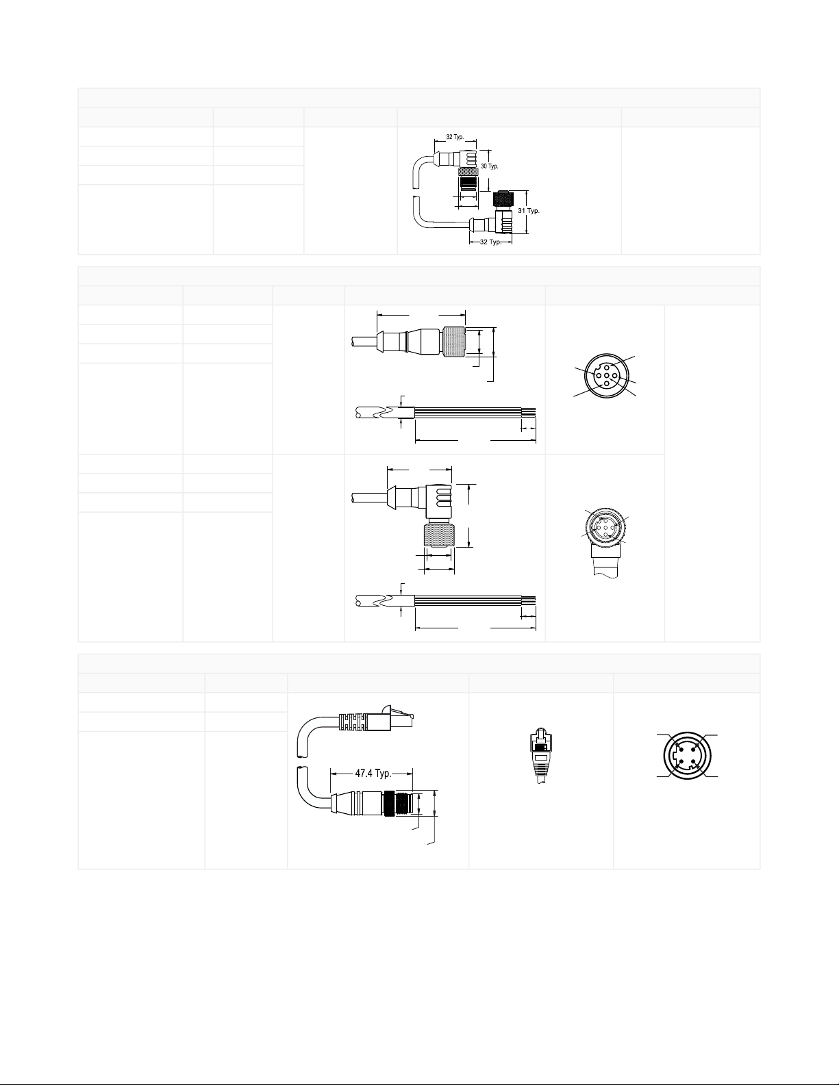
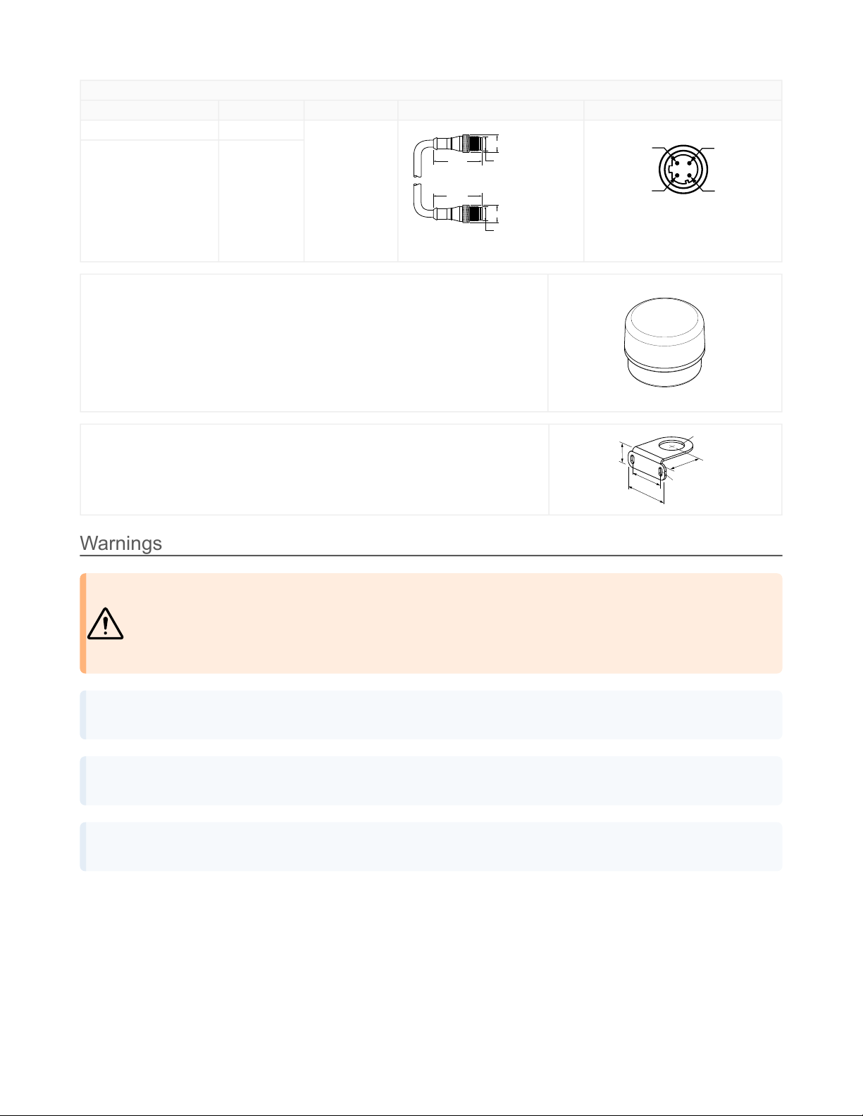
R70ER Dimensions
All measurements are listed in millimeters, unless noted otherwise.
Thisdevicemaynotcauseinterference.
Thisdevicemustacceptanyinterference,includinginterferencethatmaycauseundesiredoperationofthedevice.
L’appareilnedoitpasproduiredebrouillage.
L’utilisateurdel’appareildoitacceptertoutbrouillageradioélectriquesubi,mêmesilebrouillageestsusceptibled’encompromettre
lefonctionnement.
© Banner Engineering Corp.