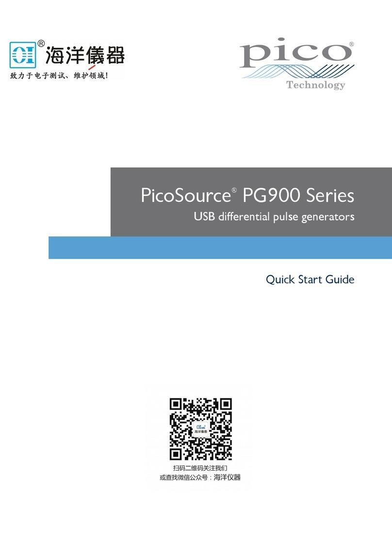
pico Technology PicoSource PG900 Series User manual

Copyright © 2016 Pico Technology. All rights reserved.
User's Guide
pg900ug.en r1
Pulse Generators
PicoSource®PG900 Series
Distributed by:
dataTec ▪ Ferdinand-Lassalle-Str. 52 ▪ 72770 Reutlingen ▪ Tel. 07121 / 51 50 50 ▪ Fax 07121 / 51 50 10 ▪ [email protected] ▪ www.datatec.de


IPicoSource PG900 Series User's Guide
Copyright © 2016 Pico Technology. All rights reserved. pg900ug.en r1
Contents
1 Introduction ................................................................................................................................ 1
1 Overview ............................................................................................................................................ 1
2 Minimum PC requirements ................................................................................................................. 2
3 Safety information .............................................................................................................................. 2
1 Symbols .................................................................................................................................. 3
2 Maximum input/output ranges ................................................................................................ 4
3 Grounding .............................................................................................................................. 4
4 External connections ............................................................................................................... 5
5 Environment ........................................................................................................................... 6
6 Care of the product ................................................................................................................. 6
4 Software licence conditions ................................................................................................................. 7
5 Trademarks ........................................................................................................................................ 8
6 Warranty ........................................................................................................................................... 8
2 Product information ................................................................................................................... 9
1 What do I get? ................................................................................................................................... 9
2 Connections ..................................................................................................................................... 10
3 How to use your pulse generator ............................................................................................. 12
1 Connection diagrams ........................................................................................................................ 12
1 TDR applications ................................................................................................................... 13
2 TDT applications ................................................................................................................... 14
3 TDT and crosstalk ................................................................................................................. 15
2 Free-running operation for SRD integrated pulse outputs .................................................................... 16
3 Free-running operation for TD outputs .............................................................................................. 18
4 External trigger operation ................................................................................................................. 19
5 Single trigger operation ..................................................................................................................... 20
4 PicoSource PG900 software ..................................................................................................... 21
1 Display area ...................................................................................................................................... 22
1 Intensified Zone .................................................................................................................... 23
2 Positive and negative pulse outputs .................................................................................................... 24
3 Tunnel diode pulse head outputs ....................................................................................................... 26
4 Tunnel diode pulse head controls ...................................................................................................... 28
5 Mode ............................................................................................................................................... 29
6 Timing .............................................................................................................................................. 30
7 External trigger ................................................................................................................................. 32
8 Trigger output .................................................................................................................................. 35
9 Display scaling .................................................................................................................................. 36
1 Vertical Scale ........................................................................................................................ 36
2 Horizontal Scale .................................................................................................................... 38
10 Undo/Redo .................................................................................................................................... 40
11 Main Menu ..................................................................................................................................... 40

ContentsII
Copyright © 2016 Pico Technology. All rights reserved.pg900ug.en r1
5 Theory of operation ................................................................................................................. 41
1 PicoSource PG900 block diagram ...................................................................................................... 41
2 Hardware components for PicoSource PG900 models ........................................................................ 42
6 Specifications and characteristics .............................................................................................. 43
1 PG900 family specifications ............................................................................................................... 43
2 Integrated step recovery diode outputs .............................................................................................. 44
3 Drive output with tunnel diode pulse heads ........................................................................................ 45
4 Timing .............................................................................................................................................. 46
5 External trigger input ........................................................................................................................ 47
6 Trigger output .................................................................................................................................. 48
7 General ............................................................................................................................................ 49
7 Declaration of Conformity ........................................................................................................ 50
Index ........................................................................................................................................... 51

PicoSource PG900 Series User's Guide 1
Copyright © 2016 Pico Technology. All rights reserved. pg900ug.en r1
1 Introduction
1.1 Overview
The PicoSource PG900 Series instruments are PC-based fast-edge pulse generators
that are fully compatible with USB 2.0 and 3.0 PCs.
The pulse generators are available in three differential output models and offer
extensive control over pulse parameters including amplitude, period, width and
deskew between output channels.
PicoSource PG911:
A two-channel pulse generator based on Step-Recovery Diode
(SRD) technology. It produces two pulses with opposite
polarity, up to 6 V amplitude with 60 ps rise time.
PicoSource PG912:
A two-channel pulse generator based on Tunnel Diode (TD)
technology. It is supplied with small remote tunnel diode
pulse heads that generate positive and negative 200 mV
pulses with 40 ps rise time.
PicoSource PG914:
A four-channel pulse generator based on both SRD and TD
technologies. It can produce two pulses with opposite polarity,
up to 6 V amplitude with 60 ps rise time, and two pulses with
opposite polarity, 200 mV amplitude and 40 ps rise time from
remote tunnel diode pulse heads.
PicoSource Pulse Generators are capable of producing pulses of either polarity with
very fast rise times. The generators will free-run or may be triggered from an external
source, with either positive or negative pulses, at rates of up to 1 MHz. The units are
designed to operate into 50 Ω lines.
The PicoSource instruments can be used as:
general-purpose pulse generators for the testing of semiconductors, components,
networks, electro-optical components etc.
fast rise/fall time step generators which can be used to check the dynamic
response of wide-band oscilloscopes and amplifiers
a stimulus for high-resolution TDR and TDT measurements
a step source for an ultra-wideband impulse forming network
For basic instructions on installing and using your pulse generator, please refer to How
to use your pulse generator or the Quick Start Guide supplied with your instrument.
Features
60 ps rise time at 6 V amplitude (integrated SRD pulse outputs)
40 ps rise time at 200 mV amplitude (tunnel diode pulse outputs)
1 Hz to 1 MHz repetition rate
200 ns to 4 µs pulse width
Continuous, external or manual trigger mode
Differential outputs with deskew
Low-jitter trigger input and output
Storage and carry case
USB 2.0- and 3.0- compatible

Introduction2
Copyright © 2016 Pico Technology. All rights reserved.pg900ug.en r1
1.2 Minimum PC requirements
To ensure that the PicoSource PG900 pulse generator and software operate correctly,
you must use a computer with the system requirements and one of the operating
systems shown in the table below. The performance of the instrument will be improved
with a more powerful PC, and operation will greatly benefit from a multi-core
processor.
Processor
As required by the operating system
Memory
Free disk space
Software occupies about 20 MB
Operating system
Microsoft Windows XP (SP3), Windows Vista, Windows 7,
8, 8.1 (not Windows RT) and 10.
32-bit or 64-bit version.
Ports
USB 2.0 (also compatible with USB 3.0)
1.3 Safety information
To prevent possible electrical shock, fire, personal injury, or damage to the product,
carefully read this safety information before attempting to install or use the product.
In addition, follow all generally accepted safety practices and procedures for working
with and around electricity.
The product has been designed and tested in accordance with the European standard
publication EN 61010-1:2010, and left the factory in a safe condition.
The following safety descriptions are found throughout this guide:
A WARNING identifies conditions or practices that could result in injury or death.
A CAUTION identifies conditions or practices that could result in damage to the
product or equipment to which it is connected.

PicoSource PG900 Series User's Guide 3
Copyright © 2016 Pico Technology. All rights reserved. pg900ug.en r1
1.3.1 Symbols
These safety and electrical symbols may appear on the product or in this guide.
Symbol
Description
Direct current
Alternating current
Earth (ground) terminal
This terminal can be used to make a measurement
ground connection. It is not a safety or protective
earth.
Chassis terminal
Possibility of electric shock
Caution
Appearance on the product indicates a need to read
these safety instructions.
Static awareness. Static discharge can damage parts.
Do not dispose of this product as unsorted municipal
waste.
WARNING
To prevent injury or death use the product only as instructed and use only
accessories supplied or recommended. Protection provided by the product
may be impaired if used in a manner not specified by the manufacturer.

Introduction4
Copyright © 2016 Pico Technology. All rights reserved.pg900ug.en r1
1.3.2 Maximum input/output ranges
Observe all terminal ratings and warnings marked on the product.
The table below indicates the maximum voltage of the outputs and the overvoltage
protection range for the trigger input on each pulse generator. The overvoltage
protection ranges are the maximum voltages that can be applied without damaging
the instrument.
Connection port
Maximum voltage
(output or input)
Overvoltage protection
Integrated pulse outputs
±8 V unterminated
±10 V
Do not connect a source
Drive outputs
±5 V DC or AC pk
±5 V DC or AC pk
Do not connect a source
Tunnel diode pulse head
outputs
250 mV
0 V
Do not connect a source
Trigger input
±2 V DC or AC pk
±2 V DC or AC pk
Trigger output
+3 V DC or AC pk
+4 V / –2 V DC
Do not connect a source
WARNING
To prevent electric shock, do not connect an input voltage to the integrated
pulse outputs or the tunnel diode pulse heads.
CAUTION
Exceeding the overvoltage protection range on any connector can cause
permanent damage to the instrument and other connected equipment.
CAUTION
To prevent permanent damage, do not apply an input voltage to any of the
output channels of the pulse generator.
1.3.3 Grounding
WARNING
The instrument's ground connection through the USB cable is for functional
purposes only. The instrument does not have a protective safety ground.
WARNING
To prevent injury or death, never connect the ground of an input or output
(chassis) to any electrical power source. To prevent personal injury or death,
use a voltmeter to check that there is no significant AC or DC voltage
between the pulse generator's ground and the point to which you intend to
connect it.
CAUTION
Applying a voltage to the ground input is likely to cause permanent damage
to the instrument, the attached computer, and other equipment.
CAUTION
To prevent signal degradation caused by poor grounding, always use the
high-quality USB cable supplied with the instrument.

PicoSource PG900 Series User's Guide 5
Copyright © 2016 Pico Technology. All rights reserved. pg900ug.en r1
1.3.4 External connections
WARNING
To prevent injury or death, only use the adaptor supplied with the product.
This is approved for the voltage and plug configuration in your country.
Power supply options and ratings
PicoSource
model
USB
connection
Ext DC power supply
Voltage
Current
Total power
PG900 Series
USB 2.0.
Compatible
with USB 3.0.
5 V
1.6 A pk
8 W
CAUTION
Take care to avoid mechanical stress or tight bend radii for all connected
leads, including all coaxial leads and connectors. Mishandling will cause
deformation of sidewalls, and will degrade performance.

Introduction6
Copyright © 2016 Pico Technology. All rights reserved.pg900ug.en r1
1.3.5 Environment
WARNING
To prevent injury or death, do not use in wet or damp conditions, or near
explosive gas or vapor.
CAUTION
To prevent damage, always use and store your pulse generator in
appropriate environments.
Storage
Operating
Temperature
–20 °C to +50 °C
+5 °C to +35 °C
(+15 °C to +25 °C or TCAL ± 5
°C for quoted accuracy)
Humidity
Up to 95% RH
(non-condensing)
Up to 85% RH at +35 °C
(non-condensing)
Altitude
2000 m
Pollution degree
2
1.3.6 Care of the product
The product and accessories contain no user-serviceable parts. Repair, servicing and
calibration require specialized test equipment and must only be performed by Pico
Technology or an approved service provider. There may be a charge for these services
unless covered by the Pico two-year warranty.
WARNING
To prevent injury or death, do not use the product if it appears to be
damaged in any way, and stop use immediately if you are concerned by any
abnormal behavior.
CAUTION
To prevent damage to the device or connected equipment, do not tamper
with or disassemble the instrument, case parts, connectors, or accessories.
When cleaning the product, use a soft cloth and a solution of mild soap or
detergent in water, and do not allow liquids to enter the instrument's casing.

PicoSource PG900 Series User's Guide 7
Copyright © 2016 Pico Technology. All rights reserved. pg900ug.en r1
1.4 Software licence conditions
The material contained in this release is licensed, not sold. Pico Technology grants a
licence to the person who installs this software, subject to the conditions listed below.
Access. The licensee agrees to allow access to this software only to persons who have
been informed of these conditions and agree to abide by them.
Usage. The software in this release is for use only with Pico products or with data
collected using Pico products.
Copyright. Pico Technology claims the copyright of, and retains the rights to, all
material (software, documents etc.) contained in this release. You may copy and
distribute the entire release in its original state, but must not copy individual items
within the release other than for backup purposes.
Liability. Pico Technology and its agents shall not be liable for any loss, damage or
injury, howsoever caused, related to the use of Pico Technology equipment or
software, unless excluded by statute.
Fitness for purpose. As no two applications are the same, Pico Technology cannot
guarantee that its equipment or software is suitable for a given application. It is your
responsibility, therefore, to ensure that the product is suitable for your application.
Mission-critical applications. This software is intended for use on a computer that
may be running other software products. For this reason, one of the conditions of the
licence is that it excludes use in mission-critical applications, for example life support
systems.
Viruses. This software was continuously monitored for viruses during production, but
you are responsible for virus-checking the software once it is installed.
Support. If you are dissatisfied with the performance of this software, please contact
our technical support staff, who will try to fix the problem within a reasonable time. If
you are still dissatisfied, please return the product and software to your supplier within
14 days of purchase for a full refund.
Upgrades. We provide upgrades, free of charge, from our web site at
www.picotech.com. We reserve the right to charge for updates or replacements sent
out on physical media.

Introduction8
Copyright © 2016 Pico Technology. All rights reserved.pg900ug.en r1
1.5 Trademarks
Windows is a registered trademark or trademark of Microsoft Corporation, registered
in the U.S. and other countries.
Pico Technology Limited, PicoScope and PicoSource are trademarks of Pico
Technology Limited, registered in the United Kingdom and other countries.
PicoScope and Pico Technology are registered in the U.S. Patent and Trademark
Office.
1.6 Warranty
Pico Technology warrants upon delivery, and for a period of 2 years unless otherwise
stated from the date of delivery, that the Goods will be free from defects in material
and workmanship.
Pico Technology shall not be liable for a breach of the warranty if the defect has been
caused by fair wear and tear, willful damage, negligence, abnormal working conditions
or failure to follow Pico Technology's spoken or written advice on the storage,
installation, commissioning, use or maintenance of the Goods or (if no advice has been
given) good trade practice; or if the Customer alters or repairs such Goods without the
written consent of Pico Technology.

PicoSource PG900 Series User's Guide 9
Copyright © 2016 Pico Technology. All rights reserved. pg900ug.en r1
2Product information
2.1 What do I get?
PicoSource Pulse Generator kits contain the following items:
·PicoSource PG900 Series Pulse Generator
·PicoSource PG900 software disk
·Quick start guide
·AC adaptor 5 V DC at 2 A, universal input
·USB 2.0 cable, 1.8 m
·SMA/PC3.5/2.92 wrench
·Storage and carry case
Each signal generator is supplied with additional accessories, as shown below.
Accessories
Order
number
PicoSource model
PG911
PG912
PG914
Positive 9040 40 ps TD pulse head
–
Negative 9041 40 ps TD pulse head
–
12 GHz N(f) to SMA(m) adaptor (2)
(fitted to TD pulse heads)
TA172
10 GHz 20 dB SMA(m-f) attenuator (2)
(fitted to SRD pulse outputs)
TA173
50 Ω coaxial SMA(m-m) pulse drive
cable, 60 cm (2)
–

Product information10
Copyright © 2016 Pico Technology. All rights reserved.pg900ug.en r1
2.2 Connections
Standard connectors
The PicoSource Pulse Generators have SMA connectors, compatible with both
2.92 mm (K) and PC3.5. The tunnel diode pulse heads have an N connector with a
pre-installed N(f) to SMA(m) adaptor.
Connector diagrams
The PicoSource PG911 front panel from left to right:
·Positive integrated pulse output (SRD)
·Negative integrated pulse output (SRD)
·Trigger output. Connect to an external unit. This connector sends a single-ended
voltage pulse.
·Trigger input. Connect an external signal for external triggering.
The PicoSource PG912 front panel from left to right:
·Drive 1 output connected to tunnel diode pulse head
·Drive 2 output connected to tunnel diode pulse head
·Trigger output. Connect to an external unit. This connector sends a single-ended
voltage pulse.
·Trigger input. Connect an external signal for external triggering.

PicoSource PG900 Series User's Guide 11
Copyright © 2016 Pico Technology. All rights reserved. pg900ug.en r1
The PicoSource PG914 front panel from left to right:
·Positive integrated pulse output (SRD)
·Negative integrated pulse output (SRD)
·Drive 1 output connected to tunnel diode pulse head
·Drive 2 output connected to tunnel diode pulse head
·Trigger output. Connect to an external unit. This connector sends a single-ended
voltage pulse.
·Trigger input. Connect an external signal for external triggering.
The PicoSource rear panel for all models from left to right:
·DC power input. Always use with the AC adaptor supplied with the unit
·USB 2.0 port. Use a USB cable to connect the pulse generator to your computer.
·Ground (chassis) terminal

How to use your pulse generator12
Copyright © 2016 Pico Technology. All rights reserved.pg900ug.en r1
3How to use your pulse generator
3.1 Connection diagrams
To set up your PicoSource pulse generator, follow the instructions below.
1. Install the PicoSource PG900 software using the software disk supplied, or
download it from picotech.com/downloads.
2. Plug the AC adaptor into the mains and connect the DC cable to the DC power
socket on the rear of your PicoSource pulse generator.
3. Earth (ground) terminal. Some laptop power supplies can produce electrical
noise which may interfere with your measurements. If this occurs, the earth
terminal can be connected to an external ground point (for example, on the
system you are testing) to provide a ground reference for the signal generator.
This can help to avoid external noise interfering with your signal integrity.
Alternatively, you can run the laptop using battery power.
4. Connect your PicoSource pulse generator to the PC or hub using the USB cable
supplied.
5. Once you have connected the pulse generator to the PC, run the PicoSource
PG900 software.
The following diagrams illustrate advanced setup options using a PicoSource pulse
generator, a PicoScope oscilloscope, and the device under test (DUT). In all setups,
the pulse generator shown can be substituted by the PicoSource PG914. Signal
connections should be made using precision SMA cables unless otherwise specified.
Trigger connections can be made using lower grade cables.
Diagram key

PicoSource PG900 Series User's Guide 13
Copyright © 2016 Pico Technology. All rights reserved. pg900ug.en r1
3.1.1 TDR applications
PicoSource PG900 pulse generators can be used to realize time domain reflectometry
(TDR) with a PicoScope 9300 Series sampling oscilloscope that does not have that
function (PicoScope 9301, 9302, 9321 and 9341).
Single-ended and differential connections for TDR testing, using a PicoSource pulse generator
with SRD outputs
Single-ended and differential connections for TDR testing, using a PicoSource pulse generator
with TD pulse head outputs
Connections between the pulse generator and the TD pulse heads (PicoSource PG912
and PG914 models only) should be made using the 60 cm coaxial SMA(m-m) cable
supplied.

How to use your pulse generator14
Copyright © 2016 Pico Technology. All rights reserved.pg900ug.en r1
3.1.2 TDT applications
PicoSource PG900 pulse generators can be used to realize time domain transmission
(TDT) with a PicoScope 9300 sampling oscilloscope without that function (PicoScope
9301, 9302, 9321, and 9341). They also offer the versatility of a remotely-placed
signal generator for long line or installed system testing when used with any of the
PicoScope 9300 models.
Single-ended and differential connections for TDT testing, using a PicoSource pulse generator
with SRD outputs

PicoSource PG900 Series User's Guide 15
Copyright © 2016 Pico Technology. All rights reserved. pg900ug.en r1
3.1.3 TDT and crosstalk
PicoSource PG900 pulse generators can be used with a PicoScope 9341 four-channel
sampling oscilloscope for simultaneous time domain transmission (TDT) and crosstalk
assessment.
Single-ended and differential connections for simultaneous TDT and crosstalk assessment, using
a PicoSource pulse generator with SRD outputs

How to use your pulse generator16
Copyright © 2016 Pico Technology. All rights reserved.pg900ug.en r1
3.2 Free-running operation for SRD integrated pulse outputs
Integrated pulse outputs based on SRD technology are available with the PicoSource
PG911 and PG914 pulse generators. Follow the setup instructions below using the
PicoSource PG900 software.
1. To switch on the positive SRD generator, click Positive Out in the Output
menu, and then click On.
2. Make sure that Period Source is set to Int Clock.
3. Make sure the Trigger is set to Continuous.
4. Set the Period in the Timing menu to provide the operation rate. Set the
desired period value from 1 µs to 1 s (1 MHz to 1 Hz).
5. Set the Width in the Timing menu. Set the desired value from 200 ns to 4 s.
6. Set the desired Limit of output amplitude, from 2.5 V to 6 V, to protect the
device under test. The change needs to be confirmed whenever the limit is
increased.
7. Set the desired output Amplitude from 2.5 V to 6 V.
Other manuals for PicoSource PG900 Series
1
This manual suits for next models
3
Table of contents
Other pico Technology Pulse Generator manuals
Popular Pulse Generator manuals by other brands

Princeton Instruments
Princeton Instruments Roper Scientific PG-200 manual

Gyrus Acmi
Gyrus Acmi PlasmaKinetic SuperPulse user manual

Agilent Technologies
Agilent Technologies 81104A quick start guide

AnaPico
AnaPico APSIN Getting started

LG
LG TEC Multi instruction manual

AVTECH ELECTROSYSTEMS LTD.
AVTECH ELECTROSYSTEMS LTD. AVOZ-D6-B instructions