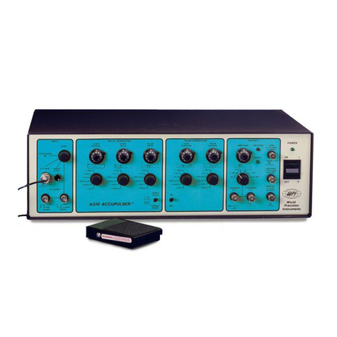
Princeton Instruments Roper Scientific PG-200 User manual

-~
ARTISAN
®
~I
TECHNOLOGY
GROUP
Your definitive source
for
quality
pre-owned
equipment.
Artisan Technology
Group
Full-service,
independent
repair
center
with
experienced
engineers
and
technicians
on staff.
We
buy
your
excess,
underutilized,
and
idle
equipment
along
with
credit
for
buybacks
and
trade-ins
.
Custom
engineering
so
your
equipment
works
exactly as
you
specify.
•
Critical
and
expedited
services
•
Leasing
/
Rentals/
Demos
• In
stock/
Ready-to-ship
•
!TAR-certified
secure
asset
solutions
Expert
team
ITrust
guarantee
I
100%
satisfaction
All
tr
ademarks,
br
a
nd
names, a
nd
br
a
nd
s a
pp
earing here
in
are
th
e property of
th
e
ir
r
es
pecti
ve
ow
ner
s.
Find the Princeton Instruments PG-200 at our website: Click HERE

Manual Version 2
Revision D
August 11, 1998
Artisan Technology Group - Quality Instrumentation ... Guaranteed | (888) 88-SOURCE | www.artisantg.com

Artisan Technology Group - Quality Instrumentation ... Guaranteed | (888) 88-SOURCE | www.artisantg.com

iii
Table of Contents
Introduction.......................................................................................................... 7
Unpacking and Initial Checks.............................................................................................7
Introduction to the PG-200..................................................................................................9
How Gated Detectors Operate ..........................................................................................10
Specifications....................................................................................................................11
Hardware Overview..........................................................................................................14
Before Operating the PG-200............................................................................................15
Chapter 1 Operation..........................................................................................17
Gating the Detector with the PG-200................................................................................17
Sweeping the Gate Pulse Delay........................................................................................19
PG-200 Triggered by an External Source.........................................................................20
Trigger Modes...................................................................................................................20
Gate Pulse Control............................................................................................................21
Inhibits ..............................................................................................................................22
Trigger Outputs.................................................................................................................22
Front Panel Key Switches.................................................................................................23
Function Key Programs.....................................................................................................24
Pulse Sweeping and Sequencing.......................................................................................27
Automatic System Settings...............................................................................................28
Front Panel Connectors.....................................................................................................29
Rear Panel Connectors......................................................................................................29
Calibration.........................................................................................................................30
Jumper Fields....................................................................................................................30
Chapter 2 Messages.......................................................................................... 33
Information Messages.......................................................................................................33
Error Messages..................................................................................................................33
Chapter 3 Firmware Upgrades.......................................................................... 35
Replacing the PROM ........................................................................................................35
Chapter 4 Serial Communication Interface.....................................................37
Chapter 5 General Description of Functions .................................................. 39
Command Example...........................................................................................................39
Error Checking..................................................................................................................40
Special Considerations......................................................................................................40
Artisan Technology Group - Quality Instrumentation ... Guaranteed | (888) 88-SOURCE | www.artisantg.com

iv PG-200 Operation Manual Version 2.D
Chapter 6 Timing Modes................................................................................... 41
Chapter 7 MCP-100 Option ............................................................................... 55
Dangers and Warnings......................................................................................................55
Introduction and Specifications ........................................................................................55
Rear Panel Controls ..........................................................................................................56
Hardware Overview..........................................................................................................57
Operation...........................................................................................................................58
High Voltage Cable ..........................................................................................................59
Chapter 8 Dual Pulse Combiner....................................................................... 61
Description........................................................................................................................61
Specifications....................................................................................................................62
Power Supply....................................................................................................................62
Operation...........................................................................................................................62
Suggested PG-200 Settings...............................................................................................63
Glossary ............................................................................................................. 65
Appendix A Serial Interface Functions............................................................ 69
WinView/WinSpec Interface Form ..................................................................................69
Linkable Object Form.......................................................................................................84
Appendix B Application Notes.........................................................................89
High Repetition Rate Operation........................................................................................89
Appendix C Stand Alone Executable Interface Functions............................. 91
Introduction.......................................................................................................................91
Command Example...........................................................................................................91
Command Descriptions.....................................................................................................92
Appendix D Serial Port Keystroke Emulation................................................. 97
Introduction.......................................................................................................................97
Byte Rate...........................................................................................................................97
Echo ..................................................................................................................................97
Command List...................................................................................................................97
RS-232 Parameters............................................................................................................98
Warranty & Service............................................................................................ 99
Limited Warranty: Roper Scientific Analytical Instrumentation......................................99
Contact Information........................................................................................................102
Index ................................................................................................................. 103
Artisan Technology Group - Quality Instrumentation ... Guaranteed | (888) 88-SOURCE | www.artisantg.com

Table of Contents v
Figures
Figure 1. Diagram of an MCP image intensifier...............................................................10
Figure 2. Internal Trigger Output configuration...............................................................31
Figure 3. Delayed Trigger Output configuration..............................................................31
Figure 4. Aux Delayed Trigger Output configuration. .....................................................31
Figure 5. PG-200 Front Panel Board.................................................................................32
Figure 6. PG-200 Processor Board....................................................................................36
Figure 7. System configuration with laser pulses less frequent than CCD readout..........42
Figure 8. Timing for experiment depicted in Figure 7......................................................43
Figure 9. System configuration for allowing multiple laser pulses to be averaged on the
CCD. .........................................................................................................................44
Figure 10. Timing example depicted in Figure 9..............................................................45
Figure 11. System configuration for experiments having jittery laser..............................45
Figure 12. Timing for example depicted in Figure 11......................................................46
Figure 13. System configured for experiment with long or unpredictable delay. ............47
Figure 14. Timing for configuration illustrated in Figure 13............................................48
Figure 15. System configuration for experiment where internal frequency generator
electronically delays the laser...................................................................................49
Figure 16. Timing for system configuration depicted in Figure 15..................................50
Figure 17. System configuration for system requiring two triggers. ................................51
Figure 18. Timing for configuration depicted in Figure 17..............................................52
Figure 19. Use of multichannel delay generator to control experiment and WinView/
WinSpec timing.........................................................................................................53
Figure 20. Timing for experiment depicted in Figure 19..................................................53
Figure 21. Dual PG-200 Pulse Combiner. ........................................................................61
Figure 22. Combiner maximum pulse separation. ............................................................63
Artisan Technology Group - Quality Instrumentation ... Guaranteed | (888) 88-SOURCE | www.artisantg.com

vi PG-200 Operation Manual Version 2.D
This page intentionally left blank.
Artisan Technology Group - Quality Instrumentation ... Guaranteed | (888) 88-SOURCE | www.artisantg.com

7
Introduction
Unpacking and Initial Checks
Carefully remove the PG-200 Pulser from the carton and inspect both the pulser and
carton for any signs of shipping damage. In case of shipping damage, contact the shipper
and Princeton Instruments, Inc. at once for instructions. Read all warnings and
instructions below before operating the pulser.
Make a backup copy of the calibration disk. It contains calibration constants plus utilities
to be used in the event of a battery failure. A README file contains instructions.
This instrument operates at potentially lethal voltages. Internal voltages exceed 1000
volts even though the high voltage gate output pulses have magnitudes of 200 volts.
Unauthorized tampering with its operation may render the PG-200 dangerous and is
prohibited. To avoid possible hazard to personnel, use the instrument only with the
proper connectors and cables and only for the purposes for which it is designed. If used
with Princeton Instruments, Inc. detectors, the BNC type cable supplied with the pulser
or a similar cable should be used (50
, 25-35 pF/foot, 3 ft. long). If the pulser is to be
used in some other application, adequate precautions must be taken to prevent persons
from making contact with the output of the pulser.
Never operate the PG-200 without the ground prong of the supplied power cord plug
making contact with an earth ground contact of a socket outlet, i.e. never “float” the PG-
200. To avoid shock or injury, never operate the PG-200 without all covers in place. If
internal jumper plugs must be reconfigured, always turn off power and wait at least 5
minutes before removing covers. The extra time is needed for high voltage capacitors to
discharge to safe levels.
This instrument may be damaged if operated with the line selector set up incorrectly or if
the wrong fuse is installed. Before applying power, verify that the line voltage selector
card in the rear panel power entry module is in the correct position. The selected voltage
may be seen through the clear window in the power entry module.
To change line voltage selection, remove the line cord, slide the window to the side, and
eject the fuse by pulling the fuse pull lever out. Using needle-nose pliers, remove the
small printed circuit card and reorient it so the desired line voltage will be visible
through the window when it is reinstalled. Reinstall the card in the new orientation,
replace the fuse with the proper value for the voltage chosen, slide the plastic window to
the side, and plug in the line cord. Line voltage and fuse values are marked on the PG-
200 rear panel.
DANGERS
WARNINGS
Artisan Technology Group - Quality Instrumentation ... Guaranteed | (888) 88-SOURCE | www.artisantg.com

8 PG-200 Operation Manual Version 2.D
The PG-200 uses a three wire power cord for connection to the power source and to a
protective ground. The exposed metal parts of the instrument, including the BNC shields,
are connected to the outlet ground to protect against electrical shock. Always use an
outlet which has a properly connected ground. Never make connections to other
instruments which might have voltages on BNC shields. Disconnecting the protective
earth terminal, inside or outside the PG-200, or tampering with its operation may render
the PG-200 dangerous and is prohibited.
The air intake for the PG-200 is on the bottom of the unit, the exhaust fan at the rear. The
PG-200 should never be placed over another unit which vents warm air through the top
cover thereby causing the PG-200 to take in warm air. Also the PG-200 should never be
positioned so that the rear exhaust is blocked. If either type of placement is attempted,
the TEMP HI error message may be displayed, indicating that the internal ambient
temperature has exceeded 50°C. If this error message is observed, power down the unit
immediately and do not power up until the cause of the over-heating is remedied.
The PG-200 is designed to drive only 1 M
terminated ICCD detectors. Attempting to
operate an ICCD with 50
termination will most likely result in damage to the pulser.
The high voltage gate pulse BNC output is on the rear panel of the PG-200. Never
connect the gate pulse output to an oscilloscope that is not rated for voltages of at least
±250 volts. The low voltage gate pulse monitor BNC is in close physical proximity to the
gate pulse to maintain pulse fidelity. The gate monitor is designed as a high impedance
timing reference for oscilloscope monitoring and is not capable of driving loads such as
TTL inputs. Caution should be exercised not to confuse the two rear panel outputs.
The EXTERNAL TRIGGER IN input BNC is rated for a maximum input voltage of
±10 volts and a maximum power of 2 watts. Both conditions must be satisfied or damage
to the PG-200 may result. Caution should be used when the external trigger input
impedance is set for 50
since 20 volts DC will damage the pulser.
Artisan Technology Group - Quality Instrumentation ... Guaranteed | (888) 88-SOURCE | www.artisantg.com

Introduction 9
Although the PG-200 output trigger BNCs are normally set for 5 volt levels and are TTL
compatible, on some units one or more outputs may be specially modified for 15 volt
levels. If a modified 15 volt output is connected to a TTL input, damage to the TTL input
instrument will result.
When operating at wide pulse widths, the duty factor should be restricted to
80%.
Higher duty factors will cause unpredictably lower output levels, which in turn may
cause unpredictable gain, non-linearity, loss of resolution and other problems. As a
result, for operation at high duty factors and with long on times, the shutter mode will
usually give more satisfactory results.
Introduction to the PG-200
The PG-200 Programmable Gate Pulse Generator combines the functions of a high
voltage gate pulse generator and a sophisticated timing source/delay generator. It is
similar to the Princeton Instruments FG-100 and PG-10 pulsers in that it is primarily
intended to provide high speed gating of proximity-focused microchannel plate image
intensifiers. The PG-200 matches the relatively high speed performance of the FG-100,
extends pulse timing to the relatively long times of the PG-10, and has other advanced
features such as continuously variable pulse widths above 3 nsec, simultaneous gating of
two detectors (optional), automatic sweeping of gate pulse delays and other automation
and communications capabilities.
The PG-200 has been designed to drive ICCD detectors with 1M
termination and will
not drive ICCD detectors with 50
termination. Driving an ICCD with 50
termination
will most likely result in damage to the pulser. See the ICCD detector manual for
information on modifying your ICCD detector for 1 M
termination.
The PG-200 is designed to operate in either a stand-alone mode with control through a
front panel keyboard or with control by computer through a serial interface. Using the
serial interface, the PG-200 will be controllable directly from either WinSpec or
WinView software.
The PG-200 front panel has the following features:
External/internal trigger mode selection
Optional optical trigger input
External trigger level set digitally or by potentiometer, selectable input impedance,
AC/DC coupling, ± trigger edge select, “triggered” indicator
Inhibit inputs used to disable pulsing
Internal frequency generator trigger output
Programmable delayed trigger outputs
Dedicated function keys for gate pulse delay, gate pulse width, delayed trigger
output, input trigger level monitor, input trigger mode select
Additional keys for features such as gate pulse delay “box-car” like sweep, pulse
sequences, internal trigger frequency set, panel dim, parameter review, initialize, etc.
Artisan Technology Group - Quality Instrumentation ... Guaranteed | (888) 88-SOURCE | www.artisantg.com

10 PG-200 Operation Manual Version 2.D
20 character vacuum fluorescent display providing an easily readable, high
luminescence display
Battery backed up memory to save settings and instrument calibration constants
The rear panel has outputs for up to two simultaneous high voltage gate pulses (the first
is standard, the second optional), gate monitors, a programmable TTL delayed output
trigger and an RS-232 serial interface.
How Gated Detectors Operate
The PG-200 is readily interfaced to the IRY, IPDA, and ICCD series detectors equipped
with internal 1 M
terminators. Connect the pulser HV gate output to the detector using
a 3 ft. (or shorter) BNC connector cable (50
impedance).
The main structural features of Princeton Instruments IRY, IPDA, and ICCD detectors
are shown in Figure 1.
Photocathode
Quartz window
MCP electron intensifier
Phosphor Fiber-optic coupler CCD or diode array
Cold finger
The proximity-focused MCP image intensifier is shown in Figure 1 optically coupled to
a CCD or diode array with a fiber optic window. A fiber optic taper may also be used, or
a lens assembly.
In the Shutter mode of operation for ICCD detectors (CW for IRY/IPDA) the
photocathode potential is held approximately 200 volts more negative than the potential
of the MCP input. With this configuration the intensifier “sees” light. The Shutter/CW
mode of operation therefore does not require the use of the PG-200 to turn the image
intensifier on and off.
In the Gate mode, the photocathode potential is held approximately 20-40 volts more
positive than the potential of the MCP input and therefore the photoelectron image or
spectrum cannot reach the MCP. To turn the image intensifier “on,” the PG-200 Pulse
Generator produces a negative pulse of approximately –200 volts amplitude. This pulse,
is applied to the photocathode, and renders it for the duration of the pulse more negative
Figure 1.
Diagram of an
MCP image
intensifier.
Artisan Technology Group - Quality Instrumentation ... Guaranteed | (888) 88-SOURCE | www.artisantg.com

Introduction 11
than the MCP and therefore the “photoelectron image or spectrum” is transmitted to the
MCP and intensified by the MCP.
The MCP intensified “electron image or spectrum” is accelerated and focused (proximity
focusing) onto the phosphor, where it is converted to a “photon image or spectrum” with
a further optical gain. This “photon image or spectrum” is transmitted to the individual
pixels through the phosphor and the diode array or CCD optical fiber coupler. There it is
detected, stored, and then read out.
High precision gating depends on the control of a few key parameters, listed below.
The ability to turn on and off the photocathode with relatively no iris effect, i.e.
“switching” on and off the entire photocathode area virtually simultaneously.
Unfortunately at the present time this cannot always be fully achieved. The edges of
the photocathode are turned on first and off first, and the opposite is true for the
center of the photocathode. This iris effect is typically less pronounced for extended
red photocathodes since their conductivity is usually higher. It is of course most
pronounced when the pulse time is very short.
The triggering mechanism must be precise and flexible. The PG-200 can trigger on
either a negative or a positive edge. Low amplitude signals can be used so that direct
signals from a photosensor can trigger without the need for amplification. The PG-
200 has a trigger port which accepts a trigger signal from a photosensor directly.
The inherent internal delay time (propagation delay), i.e. the time duration from the
triggering of the PG-200 to the time it produces the high voltage gating pulse. To
overcome the propagation delay problem, the user must adopt one of two general
approaches: pretrigger the PG-200 prior to triggering the monitored phenomenon,
e.g., laser pulse; or optically delay the arrival of the monitored light signal to the
MCP window. The PG-200 has a minimum propagation delay time of about 20 nsec.
The pulse delay time must be precisely settable and repeatable over as wide a range
as possible. In addition to the obvious instrument flexibility obtained through such a
wide range of delay variability, it also greatly facilitates initial experimental setup
where sweeping the gate pulse delay provides the means to easily “capture” the light
phenomenon.
The pulse should have short rise and fall times to provide good temporal resolution.
Specifications
All PG-200 parameter measurements are made using a Princeton Instruments detector
simulator, since the PG-200 is designed to drive Princeton Instruments ICCD detectors
fitted with high impedance (1 M
) terminators. The PG-200 will most likely be damaged
if driving a 50
ICCD is attempted.
Delay measurements are made at the PG-200 rear panel, calculated from input trigger
leading edge (10% amplitude) to gate pulse leading edge (10% amplitude).
Warm-up time: Approximately 15 minutes
Time base:
Accuracy: ±3 nsec for minimum time interval
Precision: ±1 nsec or 0.1% whichever is greater
Artisan Technology Group - Quality Instrumentation ... Guaranteed | (888) 88-SOURCE | www.artisantg.com

12 PG-200 Operation Manual Version 2.D
Jitter: < 0.5 nsec or 0.05% whichever is greater
Temperature drift: < ±1 nsec or 200 ppm per degree C, whichever is greater.
Total temperature drift is less than 500 ppm immediately after time base
calibration.
Gate pulse magnitude: –200 volts typical, –180 to –220 volts absolute, into 1 M
terminator.
Gate pulse peak amplitude ringing: ±20 volts
Gate pulse undershoot: < 40 volts
Gate pulse second undershoot: < 30 volts
Gate pulse rise/fall time: < 3 nsec for a pulse width of 3-14 nsec
< 10 nsec for a pulse width of 15-199 nsec
< 30 nsec for a pulse width > 200 nsec
Maximum gate pulse repetition rate:
10,000 Hz normally
5,000 Hz with delay sweeping (“box-car” mode)
1,900 Hz with pulse sequencing
Internal trigger rep rate: 2-10,000 Hz ±3% accuracy
Internal trigger out pulse: 5 V negative logic BNC output,
factory modifiable to 5 V/15 V positive or negative logic,
peak power = 0.5 W,
peak current 1.5A typical,
width > 10 µsec, rise/fall time < 7 nsec,
coincident with internal trigger within 2 nsec.
Gate pulse delay, external trigger mode: Continuously adjustable in 1 nsec
increments up to 80 msec. Gate delay + gate width cannot exceed a total time of
80 msec. Typical minimum delays are:
at 3-14 nsec widths: 20 nsec delay, 25 nsec max.
at 15-199 nsec widths: 35 nsec delay, 42 nsec max.
at > 200 nsec widths: 65 nsec delay, 75 nsec max.
with delay sweep: minimum delay (dependent on width) +20 nsec
Gate pulse delay, internal trigger mode: Continuously adjustable in 10 nsec
increments. (The internal frequency generator output, Internal Trigger Out can
be used in external trigger mode to achieve gate pulse delay increments of 1
nsec. A BNC cable must be connected from Internal Trigger Output to the
external trigger input.
Gate delay sweep: “Box-car” mode with delay step size programmable from 1 nsec –
80 msec, delay step count (number of delay steps) from 1 – 16,000. Normal gate
pulse delay specs cannot be exceeded, gate delay + gate width cannot exceed 80
msec total.
DELAYED TRIGGER OUT and AUX DLY’D TRIG OUT do not sweep with
gate pulse.
Maximum pulse rate = 5 kHz.
Artisan Technology Group - Quality Instrumentation ... Guaranteed | (888) 88-SOURCE | www.artisantg.com

Introduction 13
Pulse sequence: Multiple pulse producing mode where 1-250 pulse points are
produced in sequence. Gate delay, width, Delayed Trigger Out, and Aux Del’d
Trig Out can be varied. Gate width must remain within 1 of 3 ranges: < 15 nsec,
15-199 nsec, > 15 nsec during sequence. Maximum pulse rate = 1.9 kHz.
Gate pulse width: 3.5 nsec to 80 msec continuously adjustable in 1 nsec increments,
except below 15 nsec where it is adjustable in 2 nsec increments. Gate delay +
gate width cannot exceed 80 msec total. Width is measured FWHM (Full width
at half maximum amplitude).
DELAYED TRIGGER OUT pulse: Initially synchronized to trailing edge of high
voltage gate pulse, i.e. delayed from trailing edge of gate pulse by 20 µsec. Sync
delay can be varied from 1-100 µsec. Delays can also be programmed from input
trigger in 1 nsec increments, 200 nsec – 80 msec.
5 V negative logic BNC output, modifiable to 5 V/15 V negative or positive
logic, peak power = 0.5W, peak current 1.5A typical, width >1 µsec, rise/fall
times < 7 nsec.
AUX DLY’D TRIG OUT: Initially synchronized to trailing edge of high voltage gate
pulse, i.e. delayed from trailing edge of gate pulse by 20 µsec. Sync delay can be
varied from 1-100 µsec. Delays can be programmed from input trigger in 80 nsec
(±80 nsec accuracy) increments, 1 µsec – 80 msec. TTL compatible (HC series
TTL) 5 V negative logic BNC output, modifiable to 5 V positive, width >1 µsec,
rise/fall times < 7 nsec.
Pulse monitor: Gate pulse timing reference with an approximate amplitude of –2 volts
(100:1 ratio capacitive divider). For longer gate widths, the pulse monitor may
appear to be differentiated. However, the vertical edges of the pulse monitor still
accurately represent the leading and trailing edges of the gate pulse.
External trigger input, electrical: 5 nsec minimum pulse width, BNC connector,
±10 V range, 40 mV sensitivity, 50/2000
impedance, AC/DC coupling, 2 W
maximum power into 50
, ±20 volts maximum voltage (both conditions must
be satisfied).
Manual external trigger inputs can be simulated by polarity switch toggling
although extra triggers will probably be generated due to switching noise.
External trigger input, optical: 5 nsec minimum pulse, SMA connector, 400-1150
nm, 0.5 A/W at 850 nm. Required settings: 50
trigger impedance, trigger
polarity negative, trigger level < 0 V, e.g., –1 V.
INHIBIT/INHIBIT inputs: TTL compatible; ±15 volts maximum voltage, < 50 nsec
internal delay. Without connections the PG-200 is always enabled.
INHIBIT is a negative logic INHIBIT input.
Dual gate pulses:
Gate delay skew:
at 3-14 nsec widths:
2 nsec
at 15-199 nsec widths:
5 nsec
at 200+ nsec widths:
10 nsec or 0.1%, whichever is greater
Artisan Technology Group - Quality Instrumentation ... Guaranteed | (888) 88-SOURCE | www.artisantg.com

14 PG-200 Operation Manual Version 2.D
Gate width skew:
at 3-14 nsec widths:
2 nsec
at 15-199 nsec widths:
3 nsec
at 200+ nsec widths:
4 nsec or 0.1% whichever is greater
Serial interface: RS232-C, 1 start bit, 8 data bits, 1 stop bit, no parity, 9600 baud.
Battery backed-up memory: Data retention is good for 10 years under normal
conditions.
Operating environment: 20-30°C, relative humidity 10-80%
Size: 3.5
H, 17
W, 13
D
Weight: 17 lb.
Power: 95-130 V RMS, 210-260 V RMS
50-60 Hz
200 VA maximum
Hardware Overview
The PG-200 contains at least three PC boards, depending on the options purchased with
it. The three basic boards are the Processor, Front Panel and Pulser Boards. Also inside
the case are a line filter, power supply transformer, and a power line disconnect safety
switch.
Never rely on the power line safety switch to turn off the high voltage inside the pulser.
Always disconnect the line cord and wait at least 5 minutes before removing the PG-200
covers. The extra time is needed to discharge the high voltage capacitors to safe levels.
The Processor Board contains the power supply for all the system logic plus a
programmable high voltage power supply for gate pulses. The high voltage power supply
must be adjusted for different gate pulse widths to maintain relatively constant gate pulse
amplitudes. If a high voltage overload condition occurs, the supply is disabled and can
only be re-enabled by turning power off then turning power back on. If the problem
persists, power should remain off until it is resolved. Also included on the Processor
Board is a microprocessor with EPROM and battery backed up RAM, 8 channel ADC, 4
channel DAC, timers, counters, serial interface, auxiliary delayed trigger output,
keyboard controller, parallel I/O registers, internal ambient temperature monitor, and
crystal clock references.
The Front Panel Board contains control circuitry for all front panel functions including
key switches, alpha-numeric display, BNCs, slide switches, LEDs, etc. Other circuitry
includes delay generators, a 100 MHz oscillator, buffers for BNC outputs, etc. The 100
MHz oscillator serves as the PG-200 time base for gate pulse timing, delay out timing,
etc. It can be calibrated for temperature drifts by comparing its frequency against the
microprocessor crystal frequency.
The Pulser Board contains the pulse shaping circuitry to produce the high voltage gate
pulses. It receives timing information from the Front Panel Board. If a system requires
DANGER
Artisan Technology Group - Quality Instrumentation ... Guaranteed | (888) 88-SOURCE | www.artisantg.com

Introduction 15
two high voltage gate outputs, two Pulser Boards are installed, each board getting the
same timing signals so that both gate pulses occur simultaneously. Both Pulser Boards
should be specially calibrated for proper parallel operation, i.e. they must be calibrated
with each other for minimum gate pulse delay and width skews. Additionally the Pulser
Board contains a gate monitor circuit which is basically a capacitive divider. The divider
produces a faithful replica of the gate pulse, however, the monitored pulse appears
distorted since it is derived from the gate pulse at the PG-200 rear panel connector and
not at the detector. The PG-200 was designed to produce proper pulses for Princeton
Instruments detectors and this apparent distortion does not affect detector performance in
any way. The monitor pulse is only useful as a high impedance oscilloscope timing
reference.
Before Operating the PG-200
Be sure to read the unpacking and initial checks section first, especially the
danger/warning subsections. After performing all initial checks including line voltage,
fuse selection, and detector termination, turn the PG-200 on using the power switch on
the rear panel. The PG-200 should go through a boot up procedure including a partial
self-test. Within about 10 seconds the display will show the READY indication, although
to realize the full performance specifications, a 15 minute warm-up period should be
observed.
The PG-200 produces high voltage gate output pulses which are delayed from an input
trigger. The input trigger can be from an external source, i.e. External Trigger mode, or
from the internal programmable frequency generator, i.e. Internal Trigger mode. The
active trigger mode is displayed by LED indication: EXT or INT above the Trigger
Select key. The Trigger Select key can be pressed to switch between modes. INHIBIT
positive and negative logic BNC inputs can be used to inhibit pulsing with the
corresponding polarity signal. Without INHIBIT connections, pulsing is always enabled.
Three output triggers are also provided. INTERNAL TRIGGER OUT is an output trigger
coincident with the input trigger time in internal trigger mode. DELAYED TRIGGER
OUT and AUX DLY’D TRIG OUT output triggers can be programmed for delays from
either the input trigger or the trailing edge of the high voltage gate pulse. The AUX
output is on the rear panel and has fewer features than the front panel output.
Artisan Technology Group - Quality Instrumentation ... Guaranteed | (888) 88-SOURCE | www.artisantg.com

16 PG-200 Operation Manual Version 2.D
This page intentionally left blank.
Artisan Technology Group - Quality Instrumentation ... Guaranteed | (888) 88-SOURCE | www.artisantg.com

17
Chapter 1
Operation
Gating the Detector with the PG-200
This section will describe how to set up the PG-200 with a Princeton Instruments
intensified detector for basic operation. In this example, the PG-200 will be the source of
timing for the system. In other examples below, external timing will be used. For this
setup, you will need a standard dual trace oscilloscope (50 MHz or faster) and some
coaxial cables. Even if this example does not correspond to your system configuration
exactly, you may want to go through it once to become familiar with the features of the
pulser.
The steps are as follows:
➧Read the Dangers and Warnings section of this manual (beginning on page 7).
➧Make sure that the PG-200 is off and the detector is not exposed to any light. Set up
the proper cooling for the detector.
➧Connect the “Pulse output” of the PG-200 (on the back panel) to the “Gate” input of
the detector using the 3 ft. coaxial cable provided with the PG-200. Make sure this
detector is 1 M
terminated (it was originally purchased for use with a PG-200).
➧Connect the pulse monitor output of the PG-200 (back panel) to channel A of a dual
trace oscilloscope using a coaxial cable without termination. Set the oscilloscope
amplifier to 1 volt/division (the pulse monitor signal is about 2 volts).
➧Connect the Internal Trigger Output of the PG-200 (front panel) to the external
trigger input of the oscilloscope. Set the oscilloscope time scale to 5 microseconds
per division. Set the oscilloscope to trigger on the falling edge (the Trigger Output is
normally a 0 to 5 V negative-logic signal).
➧Connect the Delayed Trigger Output of the PG-200 to the other equipment in your
experiment which needs to be triggered by the PG-200 (such as a laser) using a
coaxial cable without termination.
➧Also connect the Delayed Trigger Output to the B channel of the oscilloscope and set
the channel B amplifier to 5 volts/division (this is also normally a negative-logic
TTL signal).
➧Turn on the PG-200. After boot-up, the screen on the front of the instrument should
say READY.
➧Your PG-200 has an internal battery-backed memory which remembers the settings
you have programmed from one usage to the next. To insure the factory default
settings, run the function key program #9. This is done by pushing the “F”
(Function) key followed by the “9” key, followed by the “E” (Enter) key. The PG-
200 will set itself to the values shown in the table below. After restoring the factory
default settings, the screen will once again display READY.
Artisan Technology Group - Quality Instrumentation ... Guaranteed | (888) 88-SOURCE | www.artisantg.com

18 PG-200 Operation Manual Version 2.D
Pulse Length: 100 nsec
Pulse Delay (from the internal timing source which you are using
to trigger the oscilloscope):
Note that in Internal Trigger Mode, the pulse delay may vary from
the set value of 100 nsec by as much as 10 nsec depending on
calibration, i.e. in Internal Trigger Mode, pulse delays are
programmable in 10 nsec steps.
100 nsec
Delayed Pulse Output (delay from the trailing edge of the gate
pulse) 20 µsec
Trigger Source: Internal
Internal Trigger Frequency: 1 kHz
➧At this point, the PG-200 will be producing gate and delayed trigger pulses at 1 kHz.
Adjust the oscilloscope triggering and display to see these pulses.
Both pulses will be small and negative going (standard configuration). The gate
pulse monitor, on Channel A, only 100 nsec long, will be only 0.02 divisions wide
on the oscilloscope (at 5 microseconds per division). About halfway across the
oscilloscope screen, on Channel B, will be the delayed trigger output pulse, 4
microseconds long. Remember that it is normally configured for negative logic.
Pulsing can be turned off by pressing the “±” key on the front of the PG-200.
Pressing it again will turn the pulsing back on.
➧So that the timing of the Delayed Trigger Output can be changed to before or after
the gate pulse, we will remove its synchronization from the gate pulse. Thus it will
have an independent delay from the trigger and this delay can be longer or shorter
than the delay to the gate pulse. To do this, run the DLY’D TRIG’S SYNC program
(press “F” (Function), “1”, “5” and “E” (Enter)). The user interaction during the
running of this program is as follows:
PG200: DLY’D TRIG’S SYNC
PG200: DLY SYNC ENABLED
PG200: 1 = ENABLE 0 = DISABLE
PG200: ENTER # 1
USER: “0” [CR]
PG200: DISABLE
PG200: AUX SYNC ENABLED
PG200: 1 = ENABLE 0 = DISABLE
PG200: ENTER #1
USER: [CR]
PG200: ENABLE
PG200: X SYNC 1.000 µsec
Artisan Technology Group - Quality Instrumentation ... Guaranteed | (888) 88-SOURCE | www.artisantg.com

Chapter 1 Operation 19
USER: [CR]
PG200: READY
When the delayed pulse is unsynchronized, it will move about 200 nsec earlier, as its
delay (still 20 µsec), will be relative to the trigger and not the gate’s trailing edge.
➧Next set the delay of the Delayed trigger output to 200 nsec. To do this, first press
the DLY’D TRIG key. The display will say: DLY’D TRIG: _ 20 uS. Press “2” and
then press “0” twice. The display will look like:
DLY’D TRIG: 200_ 20 uS
➧Now move the cursor right using the right arrow key until it is under the “u”. Press
the up and down arrow keys to cycle between the choices “uS”, “mS” and “nS”.
When the display says “nS”, press the “E” (Enter) key, and the new gate delay will
be implemented. This can be seen on the oscilloscope. With the new shorter delay,
the time scale of the oscilloscope can be expanded to 50 nanoseconds per division
and the pulses should be easier to see.
➧Next change the gate pulse length to 5 nanoseconds. This is done by first pressing
the “Gate Width” key. This display should say: “Gate width: _ 100 nS”. Press “5”
and then “E” (Enter). For a few seconds, the message “Adjusting HV” will be
displayed. This means that the internal high voltage supply is being automatically
adjusted to maintain the same pulse output amplitude at the new pulse length. The
gate pulse will change to 5 nanoseconds wide.
➧Next change the pulse frequency to 3000 Hz. To do this, run the INT TRIG FREQ
program, by pressing “F” (Function), “2” and then “E” (Enter). Note that this is easy
to remember as the label FREQ can be found on the front panel above the “2” key.
The screen will display: INT TRIG FREQ: _ 1000 Hz
➧Move the cursor right using the right arrow key until it is under the “1”. Press the up
arrow key. The digit will increase to “2”. Pressing the up arrow key again will
increase the number to “3000”. When this is done, press “E” (Enter) and the new
frequency will be implemented. Note that the new frequency could also have been
entered numerically, as has been done with other parameter values earlier in this
example.
The internal trigger frequency value and prompt will stay displayed so that you can
keep changing the frequency until you are satisfied with the results. To return to the
READY display, press the Trigger Select key twice. This will toggle the trigger
source to External and then back to Internal, updating the display along the way.
Sweeping the Gate Pulse Delay
If the Delayed Trigger output is causing an optical pulse (such as a laser or a flash lamp),
you may want to sweep the gate pulse past it in time, to collect data at a series of times
during and after the flash. If you are taking image data with an intensified CCD camera,
the successive frames taken can represent as little as one nanosecond advance in time per
frame. These images can later be played back in “movie” mode on a computer screen.
Using this approach of sampling a fast but repetitive event, the effective frame rate that
your movie is taken at can be as high as 1 GHz!
Artisan Technology Group - Quality Instrumentation ... Guaranteed | (888) 88-SOURCE | www.artisantg.com
Table of contents
Popular Pulse Generator manuals by other brands
AVTECH ELECTROSYSTEMS LTD.
AVTECH ELECTROSYSTEMS LTD. AVIR-3-B instructions
AVTECH ELECTROSYSTEMS LTD.
AVTECH ELECTROSYSTEMS LTD. AVRQ-4-B instructions

Megaimpulse
Megaimpulse NPG30P11 user manual
HP
HP ESG E4400B Installation note
Tektronix
Tektronix TEK-DPG instructions
Kentech Instruments
Kentech Instruments CPS3-S Notes on the Use


