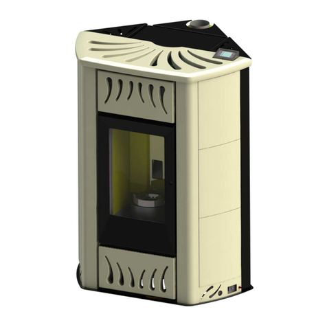
PIQUADRO CALORE BRUSCHETTA BRU70M User manual

PELLET STOVE:
BRUSCHETTA
OPERATING, INSTALLATION AND MAINTENANCE MANUAL
MOD. BRU70D - BRU70M

Operating, insta ation and maintenance manua BRUSCHETTA BRU70D - BRU70M
2
Table of contents
1. GENERAL NOTICE ...................................................................................................................................... 4
1.1 SYMBOLS ........................................................................................................................................... 4
1.2 PURPOSE AND CONTENTS OF THIS MANUAL .................................................................................. 4
1.3 INTENDED USE................................................................................................................................... 4
2. GENERAL INFORMATION .......................................................................................................................... 4
3. SAFETY STANDARDS .................................................................................................................................. 4
4. WARRANTY ............................................................................................................................................... 5
5. MANUFACTURER'S LIABILITY .................................................................................................................... 5
5.1 DELIVERY AND CHECK OF THE STOVE .............................................................................................. 5
6. SAFETY INFORMATION ............................................................................................................................. 5
6.1 RECOMMENDATIONS FOR THE TECHNICIAN ................................................................................... 5
6.2 WARNINGS FOR THE USER ............................................................................................................... 5
. STOVE DESCRIPTION ................................................................................................................................. 6
.1 TECHNICAL INFORMATION ............................................................................................................... 7
.2 FUEL TYPE AND QUANTITY ............................................................................................................... 7
.3 VISUAL MATCH OF THE STOVE ......................................................................................................... 7
8. INSTALLATION ........................................................................................................................................... 8
8.1 INSTALLATION REQUIREMENTS ....................................................................................................... 8
8.2 POSITIONING OF THE STOVE ............................................................................................................ 8
8.3 SAFELY CONNECT/OPERATE THE STOVE .......................................................................................... 9
8.4 EXTERNAL AIR INTAKE AND CONNECTION TO THE FLUE ................................................................. 9
8.5 CONNECTION TO AN INSULATED OR DOUBLE-WALL FLUE ........................................................... 10
8.6 CONNECTION TO THE FLUE ............................................................................................................. 10
8. CONNECTION TO THE FLUE ............................................................................................................. 10
8.8 USEFUL INFORMATION ABOUT CHIMNEYS ................................................................................... 11
9. COMMISSIONING .................................................................................................................................... 11
9.1 FUEL CHARGE .................................................................................................................................. 11
9.2 IGNITION ......................................................................................................................................... 11
10. ROUTINE MAINTENANCE .................................................................................................................... 13
11. CONTROL PANEL ( Mod. BRU 0M) ..................................................................................................... 13
11.1 SWITCHING OFF .............................................................................................................................. 14
11.2 ALARM MESSAGES .......................................................................................................................... 15
12. CONTROL PANEL ................................................................................................................................. 15
13. GENERAL INSTRUCTIONS .................................................................................................................... 18
14. MAINTENANCE BY YOUR SERVICE RETAILER (LOCAL AUTHORIZED RETAILER) ................................ 18
15. OPERATIONS TO BE CARRIED OUT EVERY YEAR
BY YOUR SERVICE RETAILER (Local Authorized Retailer)
..... 18
Operating, insta ation and maintenance manua BRUSCHETTA BRU70D - BRU70M
3
16. RECOMMENDATIONS FOR TECHNICIANS .......................................................................................... 18
1 . WARRANTY CONDITIONS AND CLAIMS ............................................................................................. 19
18. WARRANTY CERTIFICATE PiQuadro A+3 S.r.l. ................................................................................... 21

Operating, insta ation and maintenance manua BRUSCHETTA BRU70D - BRU70M
4
1. GENERAL NOTICE
This manual is intended for owners, installers, users and maintenance personnel of the Bruschetta series stoves and is an
integral part of the product. PiQuadro A+3 heating appliances are built and tested in accordance with the safety requirements
specified by the European directives. Fau ty stoves or mechanica and e ectrica components are covered under a two-year
warranty. During the warranty, disassemb ing or rep acement of the stove spare parts must be carried out by your Service
Retai er. Unauthorized disassemb ing or rep acements void the manufacturer's warranty. Any damage due to improper use of the
stove wi not be covered under warranty. The present manua contains instructions for the fo owing stove mode s: PELLET STOVE
BRU 0M—BRU 0D
1.1 SYMBOLS
The fo owing is a report of the symbo s used in the manua . They draw the reader's attention to possib e dangers during
insta ation and use.
WARNING/DANGER: The texts marked by this symbol contain relevant safety information and imply
potentially dangerous situations or operations.
PRESENZA TENSIONE: High voltage and danger of electricity shock.
GLOVES MANDATORY: This symbol means that gloves are compulsory for the operator in order to avoid
accidents.
WARNING: Hot surfaces
1.2 PURPOSE AND CONTENTS OF THIS MANUAL
The purpose of this manua is to provide the fundamenta information for a correct insta ation, maintenance and use of the
product. By delivering the present manual we decline any legal liability for accidents that may occur because the user has not
followed, or only partly followed, the instructions of the present manual.
1.3 INTENDED USE
BRUSCHETTA is a wood pe et stove for domestic use. Comp y with the fo owing instructions concerning the use of the stove:
Do not open the door when the stove is operating. The appliance is not intended for use by persons with limited physical,
sensory or mental capacities, or with insufficient experience or knowledge. The appliance is not intended for use by children.
Make sure children do not get close to the stove while it is operating. The above described intended use of the stove and the
relative configurations are the only ones permitted by the manufacturer: never use the stove in ways not described in the
provided instructions.
2. GENERAL INFORMATION
The identification abe on the back of the stove (figure 1) contains a the re evant information to c ear y and univoca y identify
the manufacturer, the seria number and the EC marking. Extraordinary maintenance must be carried out by qua ified personne
authorized by the manufacturer. The manufacturer is not responsib e for the consequences of improper insta ation, therefore
the installer is fully responsible for the above mentioned non-complaint installation, unauthorized changes and/or repairs and
use of non-original spare parts. The stove is to be used in comp iance with the instructions contained in this manua and safety
standards set by the specific oca egis ation where the stove is insta ed.
3. SAFETY STANDARDS
A)Directive 2006/95/EC: "E ectrica equipment designed for use within certain vo tage imits; B) Directive 2004/108/EC;
"Approximation of the aws of the Member States re ating to e ectromagnetic compatibi ity". C)Directive 89/391/EEC:
"Introduction of measures to encourage improvements in the safety and hea th of workers at work". D)Directive 89/106/EEC:
"Approximation of aws, regu ations and administrative provisions of the Member States re ating to construction products".
E)Directive 85/3 4/EEC: "Approximation of the aws, regu ations and administrative provisions of the Member States concerning
iabi ity for defective products". F)Directive 1999/5/EC: "Radio equipment and te ecommunications termina equipment and the
mutua recognition of their conformity". G) UNI 14 85/2006: "Residentia space heating app iances fired by wood pe ets -
Requirements and test methods". EN 60335-1; EN 50165; EN 50366; EN 55014-1; EN 61000-3-2; EN 14785; EN 61591; EN 60704-
3; EN 60704-2

Operating, insta ation and maintenance manua BRUSCHETTA BRU70D - BRU70M
5
4. WARRANTY
Fau ty stoves or mechanica and e ectrica components are covered under a two-year warranty. During the warranty,
disassemb ing or rep acement of the stove spare parts must be carried out by your Service Retai er. Unauthorized disassemb ing
or rep acements void the manufacturer's warranty. Any damage due to improper use of the stove wi not be covered under
warranty.
5. MANUFACTURER'S LIABILITY
By providing this manua , PIQUADRO A+3 S.r. , dec ined a iabi ity, both civi and crimina , direct or indirect, deriving from:
1. Non compliant installation
2. Partial or total failure to follow the instructions provided in this manual
3. Installation by unqualified or untrained personnel
4. Use not in compliance with safety directives
5. Modifications and repairs on the stove which are not authorised by the manufacturer
6. Use of spare parts which are not original or not specific for the model of the stove
. Lack of maintenance
8. Exceptional events
5.1 DELIVERY AND CHECK OF THE STOVE
When receiving the product, check that the de ivered materia is comp iant with the ordered goods.A so make sure that both the
User Instructions and the Insta ation instructions are in the shipping box. Check that there are no damaged or missing parts. In
the event of damages or missing parts, p ease contact your area manager, your retai er or the manufacturer.
6. SAFETY INFORMATION
6.1 RECOMMENDATIONS FOR THE TECHNICIAN
Comp y with the requirements hereafter specified:
-
Insta ation must be carried out by qua ified and authorized technicians.
-
Laws, regu ations and directives re ating to chimney configuration, venti ation/exhaustion, power supp y and other
systems must be respected.
-
The stove must be insta ed and used in settings that are deemed suitab e in comp iance with current regu ations.
-
The manufacturer dec ines any responsibi ity for accidents due to improper insta ation, parts remova , bad maintenance,
fai ure to observe current regu ations and incorrect use of the device.
-
The chimney must have a f ue draught of at east 12 PA.
-
There are neither dampers nor va ves.
6.2 WARNINGS FOR THE USER
-Prepare the stove insta ation site in accordance with oca , nationa and European regu ations;
-Do not touch or get too c ose to the g ass door;
-Do not touch the f ue;
-Do not perform any type of c eaning when the stove is operating;
-Do not remove ash;
-Do not open the g ass door;
-Do not open the ash pan;
-Keep chi dren away from the stove;
-Comp y with the requirements specified in this manua ;
-Labe s must a ways be perfect y egib e. If abe s are i egib e, contact the manufacturer for an origina spare abe ;
-Strict y fo ow the routine and specia maintenance p an;
-Do not switch the stove off by unp ugging the power cord;
-Do not c ean the stove unti it has coo ed down comp ete y;
-Touch the door on y when the stove has coo ed down;

. STOVE DESCRIPTION
The pe et stove was bui t with materia s conceived and designed especia y for this purpose. The stove main parts and contro
are described in figure 1 and in tab e 1.
TABLE. 1
A
Combustion chamber door
B
Combustion
chamber door handle
C
Air louvers
D
Combustion chamber/fire box
E
Pellets outlet channel
F
Brazier/Crucible
G
Spark plug
H
Brazier support
I
Ash pan
L
F
l
a
m
e
t
r
a
p
A3
Control panel (BRU 0M)
A5
Operating potentiometer
FIGURE.1
A2
Operating, insta ation and maintenance manua BRUSCHETTA BRU70D
The pe et stove was bui t with materia s conceived and designed especia y for this purpose. The stove main parts and contro
M
Pellet tank lid
chamber door handle
N
Fume exhaustion outlet
O
Inlet for power supply 220 volt
Combustion chamber/fire box
P
Adjustable legs
Q
Environment probe
R
Hot air outlet
S
Airflow
louvers
T
On
-
off mode potentiometer BRU 0M
U
Serial link (BRU 0D)
A2
Control panel (BRU 0D)
A4
Signal Led
A6
Identification label on the back of the stove
A6
Operating, insta ation and maintenance manua BRUSCHETTA BRU70D
- BRU70M
6
The pe et stove was bui t with materia s conceived and designed especia y for this purpose. The stove main parts and contro
s
Fume exhaustion outlet
Inlet for power supply 220 volt
-
50 Hz
off mode potentiometer BRU 0M
Control panel (BRU 0D)
Identification label on the back of the stove

Operating, insta ation and maintenance manua BRUSCHETTA BRU70D - BRU70M
7
.1 TECHNICAL INFORMATION
STOVE MODEL BRU 0M BRU 0D
Min./max. rated power Kw 3 - 3.50 -
Min./max. consumption Kg/h 0. – 1.8 0. – 1.8
Pellet tank capacity Kg 15 15
Fume exhaustion outlet diameter mm 80 80
Voltage/Frequency V/Hz 230/50 230/50
Average power consumption when in use W 130 130
Min/Max fume temperature C° 115 - 220 12 - 215
Min./max. heat output % 88.5 – 85.5 89.5 – 86.0
CO emission at 13% of min./max. O² P. % 0.012 – 0.030 0.011 – 0.030
Dimensions H x l x P 830x458x540 830x458x540
.2 FUEL TYPE AND QUANTITY
Use fue comp iant with UNI EN 14785/2006. Pe ets with the fo owing features are recommended:
Type of pe et: VIRGIN WOOD
Diameter 6 mm
Average ength 15/20 mm
Moisture < 8%
Heating power Max. 4,500 Kcal/Kg
Power/Weight Max. 5.3 Kw/Kg
.3 VISUAL MATCH OF THE STOVE
The technician must visua y and manua y match the stove parts portrayed in figure 2 and in tab e 2 with the product description.
He/she wi a so check that the parts are comp iant with current regu ations and haven't been damaged whatsoever. For any
doubts regarding damages to the device p ease contact PiQuadro A+3s.r. .
TABLE 2
a1 Brazier/Crucible a2 Combustion chamber door handle
a3 Pellet tank lid
FIG. 2

Operating, insta ation and maintenance manua BRUSCHETTA BRU70D - BRU70M
8
8. INSTALLATION
Only skilled and authorised technicians can install and connect the stove verifying that it functions properly, in compliance
with current regulations and assembling instructions. PiQuadro A+3 s.r. . dec ines any responsibi ity for damages to objects
and/or persons caused by improper insta ation.
8.1 INSTALLATION REQUIREMENTS
Before insta ing the stove carefu y read the fo owing instructions. More specifica y:
-Connect it to the f ue for fume exhaustion.
-Connect it to your power supp y system.
-Connect it to your heating system.
Connections must be comp iant with current regu ations; PiQuadro A+3s.r. . dec ines any responsibi ity for damages caused by
improper connections and systems.
8.2 POSITIONING OF THE STOVE
-Position the stove so that the p ug is easi y accessib e.
-In order to ensure a good functioning and an even distribution of temperature, eave adequate c earance and air for the
pe ets to burn, in comp iance with insta ation instructions and nationa regu ations.
-Air wi f ow through the permanent in ets on the outside wa s of the stove.
-Position the stove far from inf ammab e objects such as wooden furniture, curtains and sofas.
-If the stove is to be supported by a wooden f oor, use a f oor-protection p ate in comp iance with nationa regu ations.
-Make sure that the room can provide at east as much air as required by the device norma burning and by room
venti ation.
-For your own safety and comfort, p ease make sure that the room has a suitab e air scoop. (UNI10683)
-Do not insta the stove in bedrooms or bathrooms.
-The stove cannot be insta ed in the same room whit another heating device if two independent air pipes are not
avai ab e.
-Do not position the stove in exp osive environments.
-Check that the f oor can support the tota weight of the stove.
For a correct positing of the stove fo ow the instructions be ow:
-Put the stove on the f oor in a p ace where it can be easi y connected to the f ue and to the exhausting and therma
system.
-Connect the f ue checking that the fume exhaustion out et, on the back or on the right side of the stove, is positioned
correct y. (figure 3)
FIG. 3
FIG 4
MEASURES FOR REAR FUME EXHAUSTION PIPE CONNECTION (Figure 4)
215 mm x 80 mm
Diameter = 80 mm

Operating, insta ation and maintenance manua BRUSCHETTA BRU70D - BRU70M
9
8.3 SAFELY CONNECT/OPERATE THE STOVE
The stove is connected to the power supp y system through a cab e provided by the manufacturer. The technician is responsib e
for its correct and safe connection to the power system. P ease check that:
•
The system supports the stove’s maximum power vo tage, specified in the identification abe (Figure 1) on the
back of the device.
•
The output vo tage is between the va ues described in Tab e 4.
•
There is an earthed wa socket just behind the stove, comp iant with current regu ations.
•
The stove cab e is not dragging on the f oor causing potentia hazards to users.
•
The cab e is not fo ded or pressed.
•
Once the stove has been insta ed, make the power cab e and socket easy to reach by adu ts.
•
Do not add extension cords to the stove power cab e; in case you need extension cords immediate y contact your
PiQuadro A+3 s.r. . Service Retai er.
•
Periodica y check that the cab e has not been damaged.
•
Never p ug the stove power cab e to the power supp y system by using power strips or mu tip e sockets.
•
Never touch the cab e with damp or wet hands.
•
Keep the chi dren away from the stove.
PiQuadro A+3 s.r.l. declines any responsibility for damages caused by the failure to meet the above mentioned
requirements.
8.4 EXTERNAL AIR INTAKE AND CONNECTION TO THE FLUE
Any connection between the stove and the f ue must be protected for your chi dren's safety. For your own safety and comfort,
please make sure that the room has a suitable air scoop (UNI10683). For the good functioning of the stove, eave adequate
c earance and air for the pe ets to burn.To add an externa air scoop make a ho e on the externa wa , c ose to the stove. It must
have a free section of at east 50 cm² and be protected by an interna and externa grid. The air scoop must a so:
•
Communicate directly with the room in which the stove has been installed.
•Be correctly positioned, so that it cannot be blocked from the inside or the outside.
Do not connect the stove to flues that have already been used for other heating devices. Open the ho e for the fume exhaustion
pipe far from inf ammab e materia s. Before opening the ho e in a wooden or thermo abi e wa , the technician must use
appropriate wa fitting and adequate y cau k the stove pipe crossing it, using the insu ating materia s required by current
regu ations (Figure 14 Position 1). The same happens if the stove pipe is aid vertica y or horizonta y, near the thermo abi e wa
(Figure 26 Position 2)
A ternative y, we suggest you use industria insu ated pipes. These can be used on the outside without causing condensation
prob ems.
WARNING
A ways use pipes and connections with appropriate c ose-fitting gaskets. A the sections of a f ue must be easi y contro ed and
removed for periodic interna c eaning.
WARNING
Each 90° bend in the fume exhaustion pipe must be fixed, if possib e, with adequate "T" fittings.
WARNING
Inserting a grating at the end of the fume exhaustion pipe is forbidden.It cou d cause the stove to break down.

Operating, insta ation and maintenance manua BRUSCHETTA BRU70D - BRU70M
10
8.5 CONNECTION TO AN INSULATED OR DOUBLE-WALL FLUE
The interna dimensions of the externa f ue pipe must be of minimum 10 x 10 cm, or 10 cm diameter, and of maximum 20 x 20
cm, or 20 cm diameter.
•
By using adequate too s, check that there is a f ue draught of at east 12 PA.
•
On y use insu ated stain ess-stee pipes (doub e-wa ) with a smooth inside ining (f exib e stain ess stee pipes are not
a owed) securing them to the wa .
•
A ow space for periodic checks and annua c eaning at the ower end of the f ue.
•
Connect the stove to the f ue by using adequate pipes and fittings.
•
Make abso ute y sure to insta an anti-draught chimney in comp iance with current regu ations.
•
It is forbidden to insta f ues as shown in Figure
8.6 CONNECTION TO THE FLUE
Per un buon funzionamento fare in modo che i raccordo tra stufa e canna fumaria o condotto fumario non sia inferiore a 3% di
inc inazione nei tratti orizzonta i. La unghezza comp essiva non deve superare i 2 mt ed i tratto vertica e da un raccordo a “T” ad
un a tro (cambio di direzione) non deve essere inferiore a 1,5 mt né deve superare i 3 mt. By using adequate too s, check that
there is a f ue draught of at east 12 PA. A ow space for periodic checks and annua c eaning at the ower end of the f ue.
Connect the stove to the f ue by using adequate pipes and fittings. Make abso ute y sure to insta an anti-draught chimney in
comp iance with current regu ations.
8. CONNECTION TO THE FLUE
The interna dimensions of the f ue must be of maximum 20 x 20 cm, or 20 cm diameter. In case of a bigger f ue or bad
functioning (cracks, poor insu ation, etc.) insert a stain ess stee pipe with adequate diameter, for the entire f ue ength, from the
bottom to the top. By using adequate too s, check that there is a f ue draught of at east 12 PA. Connect the stove to the f ue by
using adequate pipes and fittings. Make abso ute y sure to insta an anti-draught chimney in comp iance with current regu ations.

Operating, insta ation and maintenance manua BRUSCHETTA BRU70D - BRU70M
11
8.8 USEFUL INFORMATION ABOUT CHIMNEYS
The f ue must be comp iant with current bui ding regu ations. The picture be ow shows how to connect the fume exhaustion pipe
to a pre-existing f ue (Figure A1 Figure A2).
9. COMMISSIONING
The stove commissioning can on y be carried out after insta ation and assemb ing. The device must then be connected to the
power supp y, water and fume exhaustion system. The stove's finishing varnish dries after the stove has been used for a coup e of
times. During the first few days, the device cou d cause unp easant sme s. Air out the room to get rid of sme s. Remove the too s
stored in the pe et tank during packaging. Make sure there is nothing eft inside the tank.
9.1 FUEL CHARGE
When loading the fuel, make sure the bag containing the pellets doesn't touch the stove. The fue has to be oaded in the tank,
in the stove upper area. To oad the fue open up the fue tank id, wearing adequate protection g oves to avoid burning your skin
when touching the hot parts in the device. In order to avoid the fire to go out, make sure that the eve of pe ets inside the tank
remains constant. Make sure that the tank id is a ways c osed. On y open it when oading the fue . Be carefu not to accidenta y
insert too s and objects, besides the fue , inside the fue tank.
9.2 IGNITION
Before switching the stove on, perform the fo owing checks:
•Check that the pe et tank is fu .
•
Remove, c ean and thorough y check the vermicu ite f ame retardant p ate, the brazier and the ash pan then reposition
them correct y.

Operating, insta ation and maintenance manua BRUSCHETTA BRU70D - BRU70M
12
WARNING
Be careful: there may be burning residues.
-Reposition the f ame retardant p ate and the ash pan;
-Reposition the ash pan making sure that the bigger ho e on its right side its with the ignition resistance pipe (Figure 18).
18);
-C ose the fire box door.
-Make sure the device is connected to the power supp y system.
-Check that the back switch is on "I".

Operating, insta ation and maintenance manua BRUSCHETTA BRU70D - BRU70M
13
10. ROUTINE MAINTENANCE
IMPORTANT
:
clean the brazier every time you switch the stove on (Position F) once every 2-3 days have the ash pan (Position I)
and the brazier support c eaned (Position L). We suggest you disassemb e the f ame trap (Position M) and the inspection p ug
once a month (Position M1) c eaning up the area by using an appropriate vacuum c eaner.
PARTS/FREQUENCY
TYPE OF CLEANING
1 DAY
Routine cleaning
2-3 DAYS
Routine cleaning
1 MONTH
Routine cleaning
1 YEAR
Extraordinary cleaning
*
*
Warning
for ordinary
maintenance
please refer to
section
Bra ier (F)
Ash pan (i)
Flame trap (M)
Flame retardant
plate (L)
Inspection plug
Fumes
(M
1
)
11. CONTROL PANEL ( Mod. BRU 0M)
For the stove commissioning, fo ow the instructions in chapter 9 (Commissioning) Move the hand e(2) of the contro pane out of
the first “off” area. The switching on and off phase is signa ed by a f ashing green LED, f ashing very fast (5 times per second). You
can fi the auger in if you switch the stove on for the abso ute first time, or for the first time after having emptied the tank:
•Move the hand e from off to max twice, in no more than 2 seconds;
•Once on max, the pe et oading wi start;
•The oading of the auger is comp ete when the pe ets get to the brazier. The operation takes about 3 minutes. After
having oaded the pe ets, se ect your desired temperature by moving the hand e.
•Set the desired temperature by moving the hand e
•La rego azione va da un minimo di 16°C (pos. Min) a un massimo di 28°C (pos. Max). According to the temperature you
chose and the room temperature, the pane board activates the stove power contro s. When the room temperature is
ower than the set temperature, the Led wi f ash green according to its ca cu ated power.
•Wait for the stove to be comp ete y switched on. Once the temperature has been reached, the Led wi stop f ashing and
remain stab e.

Operating, insta ation and maintenance manua BRUSCHETTA BRU70D - BRU70M
14
In its min. and/or max. position, the stove doesn't function on the basis of room temperature,
but only works at min. and/or max. power
Led status and its meaning are described in the fo owing tab e (Tab e 8).
STOVE DESCRIPTION LED DESCRIPTION
LED COLOUR FLASHING MEANING
Green S ow f ashing The stove is off, no a arm
Green Quick f ashing The stove is being switched on or off
Green 1 f ash The stove is on at eve 1 power
Green 2 f ashes The stove is on at eve 2 power
Green 3 F ashes The stove is on at eve 3 power
Green 4 F ashes The stove is on at eve 4 power
Green 5 F ashes The stove is on at eve 5 power
Green The ed stops f ashing The stove has reached the set temperature
Orange The ed stops f ashing The stove is set at MAX or min power
Red 1 f ash fue a arm
Red 2 f ashes Fume probe a arm
Red 3 F ashes Environment probe
Red 4 F ashes Fai ed ignition
Red 5 F ashes B ack - out a arm
Red 6 F ashes Fau ty encoder a arm
11.1 SWITCHING OFF
When you wish to switch off your stove, move the hand e in the contro pane to off.
If you know you wi not use the stove for a ong time, move the back switch to "0".
Fig. 19
Fig. 20
2
2
Table.
4

Operating, insta ation and maintenance manua BRUSCHETTA BRU70D - BRU70M
15
11.2
ALARM MESSAGES
A LED in the contro pane wi f ash in case of a arm. Here is a description (Tab e 5) of what the contro pane does, depending on
the different working stages of the stove.
ALARM MESSAGES
ALARM NAME IS DISPLAYED IF... ACTION
A arm - broken environment probe If the temperature detected by the
environment probe is ess than -20°C or
more than 70°C
If the stove is off
:
the stove remains off
and disp ays the a arm.
If the stove is being switched on or is
cooling down: the stove engages the
shut-down procedure and switches on
the a arm.
If the stove is loading fuel: The stove
engages the shot-down procedure and
switches on the a arm.
If the stove is cleaning the brazier: the
stove engages the shut-down
procedure and switches on the a arm.
If the stove is on: the stove engages
the shut-down procedure and switches
on the a arm.
A arm - Fau ty fume probe If the temperature detected by the
environment probe is ess than -20°C or
more than 300°C
A arm - B ack out Fai ed mains power source
Encoder a arm No signa from the fume exhaustion
system.
12. CONTROL PANEL
Contro Pane : Use and Functions
Led
OFF
P1
P2
P3
P4
D2 D3
D1
Led Fix Blinking
L1 Stabi ization phase Ignition Start phase
L3 Stove OFF Extinguishing phase
L4 Work phase Modu ation/Standby phase
L5 Engine Auger ON
L6 Igniter Resistance ON
L Chrono Program enab ed
L8 Heating Fan ON
Display
Disp ay
Fix Blinking
D1 Time
D2 Work Combustion Power set Combustion power change
D3 Room Thermostat set Room Thermostat change
Buttons
Tasto Click [P click] Long Pressure [P long]
P1 Disp ay other data Ignition/Extinguishing /B ock Reset
P2 Combustion Power Setting Manua Pe et Loading
P3 Thermostat Setting (+) Pe et Loading Correction
P4 Thermostat Setting (-) Combustion Fan Speed Correction
Alarms
DESCRIPTION
Display
Safety Thermostat HV1: signa ed a so in case of Stove OFF Block Er01
Safety PressureSwitch HV2: signa ed with Combustion Fan ON Block Er02

Operating, insta ation and maintenance manua BRUSCHETTA BRU70D - BRU70M
16
Extinguishing for Exhausting Temperature owering Block Er03
Extinguishing for Exhausting over Temperature Block Er05
Pe et Thermostat open (f ame return from the brazier) Block Er06
Encoder Error: No Encoder Signa (in case of P25=1 or 2) Block Er0
Encoder Error: Combustion Fan regu ation fai ed (in case of P25=1 or 2) Block Er08
Fai ed Ignition Block Er12
Lack of Vo tage Supp y Block Er15
Lack of Fue Block Er18
DAY and TIME not correct due to pro onged absence of power supp y Block Er11
Anoma y in probe contro during Check Up phase Sond
The reset of the BLOCK Condition is done by the Long Pressure of the button P1
User’s Menu (1)
Ignition/Exstinguishing
D1
D3
D2
P3
P4
P2
OFF
P1
Long
The Ignition is activated with a ong pushing of the button P1
The Ignition is signa ed by the first b inking than fix ed L1
The Work state is signa ed by the fix ed L4
The Modu ation state is signa ed by the b inking L4
The Extinguishing is activated with a ong pressure of the button P1
The Extinguishing is signalled by the blinking led L3
The Extinguishing finished =OFF state is signalled by the fix led L3
Combustion Power Setting
OFF
D2
P2
Click
C ick button P2: the disp ay D2 b inks
With other c ick of the button P2 the power is changed according to the va ues
Ex.: 1 – 2 – 3 – 4 – 5 – A (A= Automatic Combustion)
After 3 seconds the new value is memorised and the display shows as normal
Work Thermostat Setting
D2
D1
P2
P1
OFF
D3
P4
Click
P3
Click
C ick button P3 or P4: the disp ay D3 b inks
With other c ick of the buttons P3 / P4 the va ue of the thermostatis increased or decreased
After 3 seconds the new va ue is memorised and the disp ay shows as norma
Manual Pellet Loading
D1
P4
D3
D2
P3P1
OFF
P2
Long
The ong pressure of button P2 activates the Pe et Manua Loading with activation of Auger engine in
continuous way. The bottom disp ay shows the actua function
The up disp ay shows the passed oading time
To stop the oading push any button
The oading stops automatica y after 300 seconds
Pellet Loading Correction
D1
P4
P2
Long
D3D2
P1
P3
Long
OFF
The ong pressure of button P2 activates the Pe et Manua Loading with activation of Auger engine in
continuous way. The bottom disp ay shows the actua function
The up disp ay shows the passed oading time
To stop the oading push any button
The oading stops automatica y after 300 seconds
Combustion Fan Speed Correction
P3
Long
D1
P2
Long
D3D2
P1
OFF
P4
Long
The activation is with a ong pushing of the button P2
The bottom disp ay shows UEnt
The Disp ay D1 shows the b inking va ue
With buttons P3 / P4 the b inking va ue increases or decreases
The va ues are between the range – ÷ .The defau t va ue is ‘0’
After 3 seconds the new va ue is memorised and the disp ay shows as norma

Operating, insta ation and maintenance manua BRUSCHETTA BRU70D - BRU70M
17
Display
L6
D3
L8L6L5
L4L1
D1
P4
Long
L3
P3
Long
P2
Long
P1
Click
OFF
L5 L6 L8
L4L1
D1
D3
P4
Long
L3
P3
Long
P2
Long
P1
Click
OFF
D3
L8
L4L1
D1
P4
Long
L3
P3
Long
P2
Long
P1
Click
OFF
D3
L8L6L5
L4L1
D1
P4
Long
L3
P3
Long
P2
Long
P1
Click
OFF
Room
Temperature Exhausting
Temperature Combustion
Fan Speed Product
Code
L5
Whith c ick of P1.
tA= Room Temperature
tF= Exhausting Temperature
UF= Combustion Fan Speed
[RPM/Vo t]]
A 03=Product Code
Radio Remote Control
ON
OFF
123 4
The button 1 activates the Extinguishing ; the button 2 activates the Ignition
The buttons 3 / 4 decrease / increase the Power Combustion
Code Change:
On the Remote Contro :
Open the battery box moving right the cover
Modify dip-switch’s configuration and c ose the box
On the Thermoregu ator:
Switch OFF the power supp y (230 Vac)
Switch ON the Power Supp y pressing at the same time one button on the
Remote Contro waiting about 5 seconds unti an acoustic signa is emitted
confirming the code earned
User’s Menu (2)
Push contemporary the buttons P2 and P4 for three seconds to enter into User Menu (2)
To scro the Menu push the buttons P3 or P4
To enter in a submenu push the button P2
To modify the b inking va ue push the button P3 (to increase) or P4 (to decrease)
To exit push the button P1
Chrono
It a ows to programme and enab e the ignitions/extinguishing
Enab e
It enab es the Programming set.
Push the button P2 to enter
Push the buttons P3/P4 for se ect
ON= enab e programming set OFF=disab e programming set
To confirm, push the button P2, or push P1 to esc
Program
It a ows to schedu e the 3 time bands avai ab e for every day of the week
Se ect
Push the button P2 to enter
Use the buttons P3/P4 to visua ize the time bands set:
The upper disp ay visua izes the TIME SET
- - - - if the BAND is
disab ed
The bottom disp ay visua izes: DAY / BAND / ON/OFF
The ong pressure of the button P1 Enab es / Disab es the se ected time band
BAND DISABLED
TIME SET
DAY
OFF
BAND
ON
BAND
DAY
PROGRAM CHRONO ACROSS MIDNIGHT
Set the time ON for the previous day to the wanted va ue: Examp e 20.30
Set the time OFF for the previous day at: 23:59
Set the time ON for the next day at 00:00
Set the time OFF for the next day to the wanted va ue: Examp e 6:30
The system wi turn ON on Tuesday at 20.30, and wi turn OFF on Wednesday
at 6.30
Time and Date
It allows to set the current day and time
Radio Remote Control
It enab es the Radio Remote Contro
Push the button P2 to enter
Push the buttons P3/P4 for se ect
On= Enabled OFF=Disabled
To confirm, push the button P2, or push P1 to esc

Operating, insta ation and maintenance manua BRUSCHETTA BRU70D - BRU70M
18
13. GENERAL INSTRUCTIONS
WARNING
Switch the stove off and let it cool down at room temperature before carrying out maintenance. Wait for at least
an hour after shutting down the device.
WARNING
Always use anti-heat gloves to avoid possible skin burns.
WARNING
Deactivate the back switch by moving it to "0” (Figure1) Unplug the device
WARNING
Do not unplug the device or deactivate the back switch by moving it to "0" when the stove is on. This will block all
the engines in the device and hamper the exhaustion of fumes inside the stove.
WARNING
In case of flue fire, unplug the device, do not open any compartment and immediately contact the fire
department.
14. MAINTENANCE BY YOUR SERVICE RETAILER (LOCAL AUTHORIZED RETAILER)
WARNING
Extraordinary maintenance must be performed by your Service Retailer.
WARNING
Before any type of maintenance, replacing, repairing, cleaning, etc. make sure your stove has no connection
whatsoever to energy power supplies (disconnect the power supply cable from its socket)
Wear safety devices (e.g. anti-perforation gloves) when carrying out maintenance operations. Carry out
maintenance when the stove is shut down and completely cooled off.
15. OPERATIONS TO BE CARRIED OUT EVERY YEAR
BY YOUR SERVICE RETAILER (Local Authorized Retailer)
-Genera interna and externa c eaning.
-Accurate c eaning of exchanging pipes.
-Carbon-remova and accurate c eaning of the brazier and the brazier compartment.
-C eaning of engines, mechanica check of c earances and fixtures.
-C eaning of fume pipes (rep acement of pipe gaskets) and of the fume exhaustion compartment.
-C eaning of the pressure switch, rep acement of the sma si icon tube.
-Probe check
-Carbon-remova , c eaning and checking of the ignition resistance compartment, rep acing it if necessary.
-Visua match of e ectrica cab es, connections and power supp y cab e.
-C eaning of pe et tank and checking of c earances and auger/geared motor.
-Functiona test, oading of the auger, ignition, operating the stove for 10 minutes, switching off.
-Check of e ectrica parts and a e ectronic devices.
16. RECOMMENDATIONS FOR TECHNICIANS
The device must be insta ed by qua ified and trained staff who is aware of the requirements set forth by UNI EN 14785 – 2006 and
other insta ation-re ated regu ations.

Operating, insta ation and maintenance manua BRUSCHETTA BRU70D - BRU70M
19
1 . WARRANTY CONDITIONS AND CLAIMS
-The device comes along with two years of warranty, as estab ished by European Directive 1999/44/EC on purchase
goods. The starting date is the one you find on your receipt, invoice or document proving that you actua y purchased the
device on that specific day.
-PiQuadro A+3 s.r.l. warranty is Europe-wide.
-PiQuadro A+3 warranty covers a the components in the device (with the exception of g asses and common materia s).It
a so covers the rep acement costs of fau ty components.
-
The warranty is valid if: the purchaser is ab e to provide receipt, invoice or documents proving that the stove was
actua y purchased on that specific day.One of these documents is compu sory for warranty c aims.It must be shown to
your technician before the warranty c aim or it cou d void the manufacturer's warranty.
-The warranty is valid if: a due payments have been sett ed and the purchaser is not in defau t of payments.
-The warranty is valid if: it is proven that the component or spare part has a manufacturing fau t, not due to inappropriate
or wrong use, or to a ack of maintenance by the purchaser.
-The warranty is not valid if: bad functioning is due to improper f ues or chimneys, which are not comp iant with current
regu ations or device requirements.
-The warranty is not valid if: you position your stove in an area subject to anoma ous environmenta conditions or if
damages occur because of atmospheric agents, or because of c imate, chemica or e ectrochemica factors.
-The warranty is not valid if: bad functioning is due to improper insta ation, device tampering, inappropriate use and
neg igence.
-The warranty is not valid if: bad functioning is due to the use of inappropriate fue , ike wooden pe ets other than the
certified ones.
-The following are not covered under warranty:c eaning of the devices and routine maintenance.
-The following are not covered under warranty:g asses and common materia s.
-The following are not covered under warranty: accidenta damages caused by fa s or accidents during the shipping, we
are not responsib e of. Check the integrity of the device before insta ation.
PiQuadro A+3 s.r. . dec ines any responsibi ity for damages occurring, direct y or indirect y, to persons, objects and anima s
because the user has not fo owed, or on y part y fo owed, the instructions in the present manua .We a so dec ine responsibi ity
in case of improper insta ation and use, device tampering, bad maintenance, neg igence and fai ure to observe current
regu ations and directives. PiQuadro A+3 s.r. . reserves the right to change, without warning, the features and data of the
app iances described in the present manua . Some features and accessories are not inc uded in the standard equipment, their
cost sha be discussed at the time of purchase. For warranty claims on PiQuadro A+3 s.r.l. devices, it is compulsory to send the
warranty claim form below.You can also require the form to your Service Retailer.

Operating, insta ation and maintenance manua BRUSCHETTA BRU70D - BRU70M
20
This manual suits for next models
1
Table of contents
Other PIQUADRO CALORE Pellet Stove manuals
Popular Pellet Stove manuals by other brands

Centrometal
Centrometal EKO-CK P 20 Technical manual

Quadra-Fire
Quadra-Fire CB1200-C owner's manual

Ravelli
Ravelli OLIVIA STEEL Brochure for model

Centrometal
Centrometal PelTec 12 Technical instructions

Ariterm
Ariterm MYSINGE Installation and operating instructions

Quadra-Fire
Quadra-Fire CASTILEI-MBK owner's manual