Plantraco PTV16C User manual


NOTICE
The PTV16C kit is a radio-frequency "intentional radiator" device which
may be constructed from kit parts supplied by Plantraco Ltd – Planrite
Trading Company Ltd. It is designed and intended to conform to applicable
provisions of Part 15 of FCC Rules. The individual kit-builder and all
users of this device assume responsibility for lawful uses conforming to
FCC part 15 Rules. Operation is subject to the following two conditions:
1. This device may not cause harmful interference, and
2. This device must accept any interference received, including
interference that may cause undesired operation
Other FCC regulations explain how to apply for a license or other
authorization which may permit you to upgrade your PTV16C or other
equipment to accomplish any objective which the FCC sees to be in the
public interest and not interfering with other authorized uses of the radio
spectrum. FCC regulations are evolving and are becoming less restrictive,
allowing radio experimenters more and more opportunities to explore
many frequency bands, using many communications modes, with no
need for a formal license of any kind. A thorough study of Part 15 of FCC
Rules will show you the many legal uses of radio transmitting devices
which do not require licensing, either amateur or commercial. The FCC
is beginning to look out for the interest and good plans and intentions of
private citizens, community groups, and schools as never before in radio
communications history.
Do not modify your kit in any way
Do not assume that the mere fact that you purchased this kit gives you
any specific right to use it for any purpose beyond generating a low level
RF signal which is barely detectable beyond the perimeter of your personal
dwelling space.
Check your intended operating frequency very carefully, as clearly explained
in this instruction manual, to ensure you will not cause interference to
reception of licensed broadcasting.
If you are contacted by the FCC regarding use of this device, cooperate
fully and promptly.
If you receive ANY complaint about your transmissions interfering with
broadcast reception, stop or change your operation IMMEDIATELY.
Do your own homework and research to understand and comply with
present and future FCC rulings concerning devices of this kind.
Be courteous when operating your kit – Learn the Rules – Obey Them –
and Have Fun in Radio!

Table of Contents
1. Overview ................................................................................................................. 2
2. Quickstart................................................................................................................. 3
3. Your TV Receiver and Antenna................................................................................ 3
4. Testing your PTV16 ................................................................................................. 4
5. Installation on Plantraco Tri-Turbofan Blimp ........................................................... 6
6. Installation in Plastic Box Housing, and in the Desktop Rover ............................... 9
7. Notes about lawful use of the PTV16C .................................................................. 10
8. Troubleshooting ...................................................................................................... 11
9. Specifications ......................................................................................................... 12
10.Warranty and Repairs ............................................................................................ 12
1
Desktop Rover with PTV16C installed.
R/C Telepresence Vehicle with computer control capabilities.
ANew Miniature World Awaits You . . . Under the Sofa!

SECTION 1
Overview
Congratulations on your purchase of one of the smallest TV transmitter kit to be made
available - Plantraco’s PTV16C Wireless Video Camera Kit.
Ultralightweight microelectronics allow this kit to be installed in the Plantraco Tri-Turbofan
Blimp – effectively turning your indoor airship into a mobile "Eye in the Sky Blimp-Cam”.
(See Fig 1.0) Your PTV16 can also be installed in the Plantraco Desktop Rover, (our
incredibly tiny remote controlled tracked vehicle), giving you full "Mars Lander" style
video telepresence from up to 100 feet away! (See Fig 1.1) The PTV16C kit can also be
used separately for experimental TV broadcast in accordance with part 15 of FCC Rules
(see page 10).
Once assembled, this low power transmitter will broadcast a Color TV signal to your
Color (NTSC) television set tuned to UHF channel 16. For Best Results, use a Manually
Tunable TV Receiver with fine tuning - Handheld TV sets (for example CASIO Model
EV660) with digital scan tuning are reccomended for the best continuous and clear UHF
Channel 16 reception.
We have carefully designed the PTV16 to comply with part 15 of FCC regulations so as
not to cause interference with other electrical devices. Although the PTV16 is a very low
power transmitter, 150 foot operating range is easily achieved, and can be extended
with the use of more sophisticated UHF TV receiver antennas. This wireless video
camera is small, lightweight, reasonably priced and will provide you with many hours of
fun!
This camera works well with our Tri-Turbofan Blimp, our Desktop Rover, and is ideal for
Model Train enthusiasts, R/C cars, boats, and helicopters. You will find many uses for
this small wireless camera.
No downconverter needed! Works with any TV! You can carry your pocket sized TV
set with you wherever you are using your R/C vehicles! Handheld TV’s and manually
tuned TV sets provide solid reception and you can take them with you anywhere!
Explore the Alien Landscapes Around Your Home! - The Ultimate in Telepresence R/C Fun!
2
1.0 1.1

SECTION 2
Quickstart (please read the rest of the manual anyway, ok?)
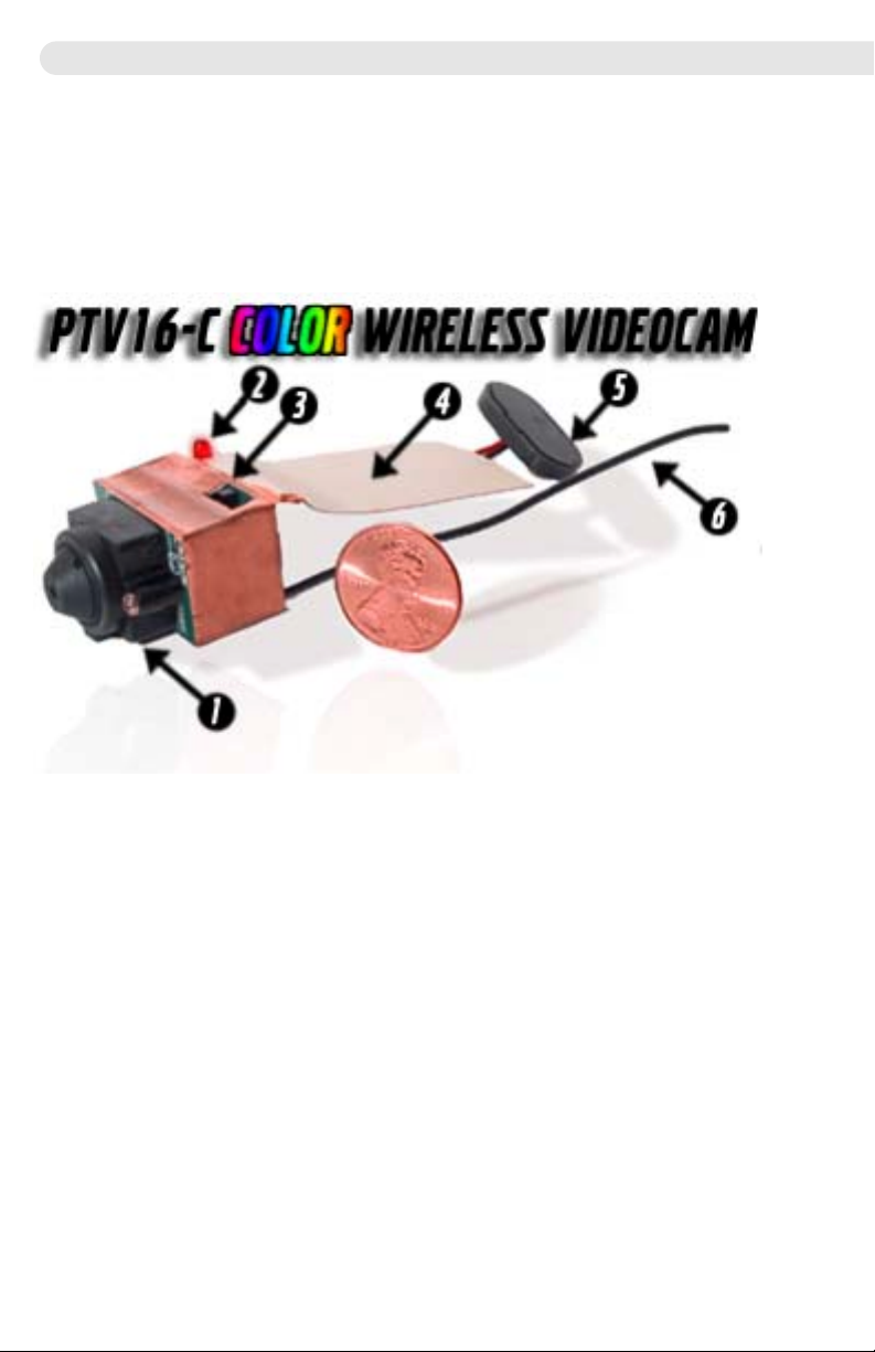
•Attach 9 Volt Battery to the PTV16C
•Position Switch on Camera to "ON" position - Note Red Power LED glows.
•Tune your NTSC TV set to UHF channel 16. Mute your Audio.
•For Best Results Use a Manually Tuned TV Set, or a Scan Tune Handheld TV Set.
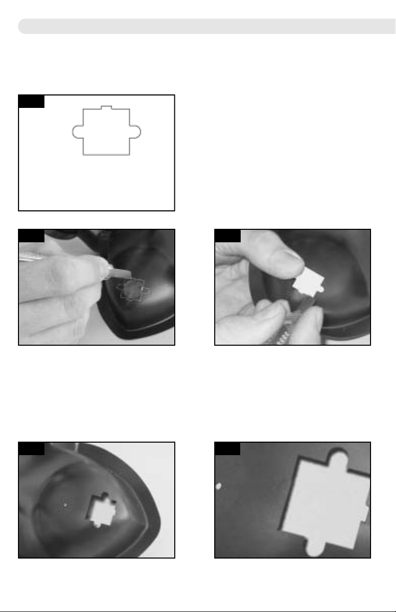
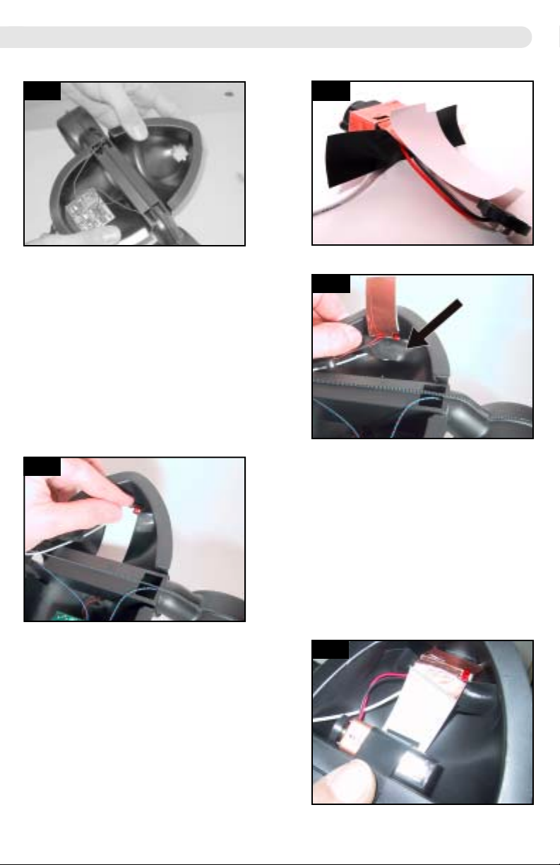
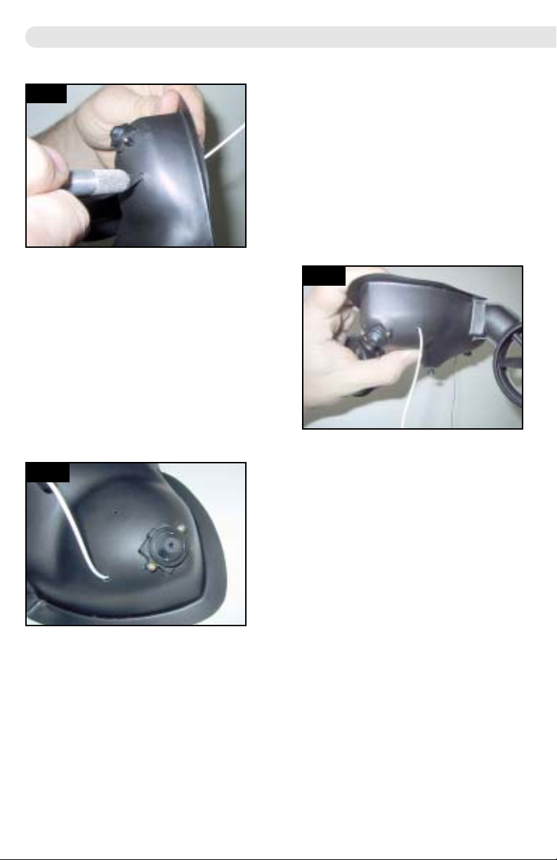
•Thats it! You are up and running! (Check Section 6 to install your cam into its plastic housing)
SECTION 3
Your TV Receiver and Antenna Selection
Configuring your TV Receiver for UHF reception.
NOTE: For Best Results, use a manual tuned TV set - or a handheld TV set with “scan tuning”.
Manually tuned TV sets with fine tuning will provide solid reception of the PTV16C broadcast.
If you wish to use the PTV16C on a modern TV set, good results can be achieved:
1. Turn down the volume or Mute your TV audio. The PTV16C does not broadcast audio signals.
2. Unscrew the Cable TV coax cable if your TV set has been used to receive Cable TV program-
ming.
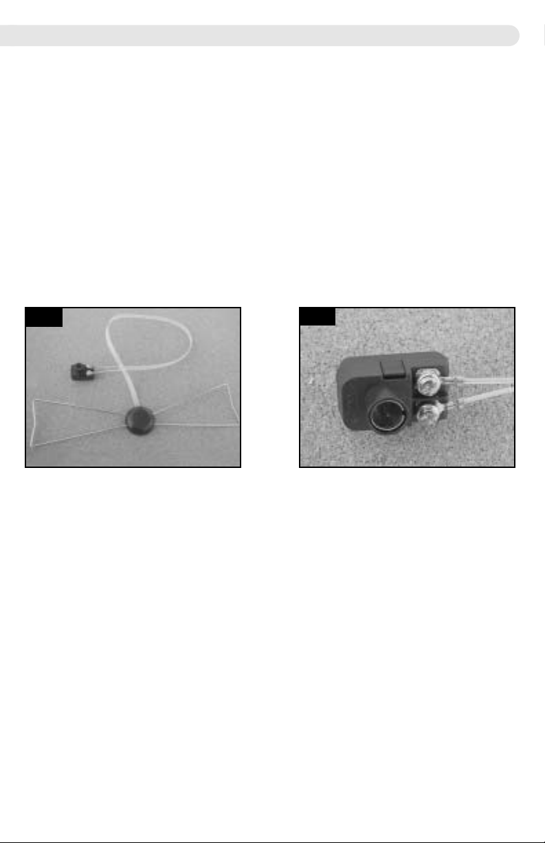
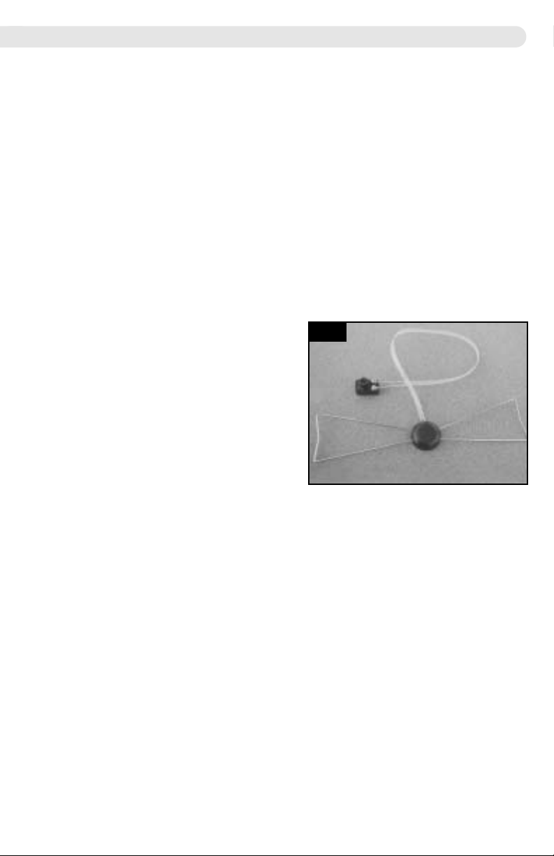
3. Connect a Bow-tie or Loop type UHF antenna to your antenna input jack of your TV set. (See Fig
3.0) If your TV set does not appear to have an input jack, it is probably a newer TV set and it will
use the cable coax input jack for the antenna input. You may need to purchase a coax adapter
(300 ohm to 75 ohm matching transformer) (See Fig 3.1) for your Bow-tie or Loop antenna (both are
available on our website for $ 8.00). If you have a portable or automobile TV set with built in ‘rabbit
ears’ type antennae, you can use this antenna.
4. Set your TV to receive off-air TV UHF reception – NOT CABLE TV! On recently
manufactured TV sets you will have to use the TV remote control to go into the TV tuner ‘set-up’
‘on-screen menu’ mode by selecting ‘MENU’, ‘TUNER SET-UP’, ‘MODE’ or some other such
selection. With so many different brands of TV sets, it is helpful to consult your TV’s manual. This
is a very important step in setting up your TV set, but the steps to setup for UHF tuning are dif-
ferent for each brand of TV. The terminology of off-air reception varies with each brand of TV – it
might say ‘AIR’, ‘ANTENNA’, ‘VHF/UHF’. Just make sure you DO NOT select CABLE! For Best
Results, use a manually tunable TV set with fine tuning, or digital scan TV tuner such as is found
in the CASIO EV660 Handheld TV Set. Manually tuned TV sets will result in better reception if
your PTV16C tuning varies slightly from 483.25 Mhz
5. Now that you have connected your UHF antenna, have muted the audio, and have tuned to
channel 16, you are ready to test reception from your PTV16C transmitter.
If you have a portable set, an old TV, or a cheap TV with dial tuning, you can do final tuning
once you have turned the PTV16C on.
Visit our website to order a Bowtie antenna for increased reception range
3
3.0 3.1

SECTION 4
Testing your PTV16C
We recommend you read through this manual completely before operating your kit –
especially page 10 which deals with issues regarding radio transmitter interference.
To make your PTV16C kit operational:
1. Carefully remove the PTV16C from its protective shipping packaging and set it on your
table. Your kit is as lightweight as we could make it so that it can be flown in our
Tri-Turbofan powered Remote Controlled Blimp. The PTV16C is encased in a copper
shield which isolates the circuitry from inductance interference. The Copper shield also
functions as a ground plane antenna. Examine Figure 4.0 and familiarize yourself with
the key components highlighted here:
1. CCD Camera Lens
2. Power ON indicator LED
3. On/Off Switch
4. Copper Ground Plane Antenna
5. 9 Volt Battery Connector
6. Main Antenna
4
Figure 4.0

2. Attach a 9V alkaline battery to the PTV16C. This camera should provide a minimum
of 3 hours of battery life when using Duracell brand Alkaline Battery. If you wish you
may use a Lithium 9V battery which can provide extended life. Check our website for
a 9V AC adapter for "hardwired" installations.
3. If you are using a Handheld TV set, switch to UHF, tune and you are ready for action.
For home TV sets and modern TV sets: Attach a UHF antenna to your Television Set.
Standard "Rabbit Ears" will work, but for better performance you can use a "Bowtie"
UHF antenna – see Fig 4.1 Turn the set on, mute the audio, and tune to channel 16.
If you have a recent model TV set, you probably will need to use your TV remote con-
trol to set the input signal to ANTENNA or AIR so that the TV tuner will be able to
receive UHF TV signals from the PTV16C. For Best Results, use a manually tun-
able TV Receiver with fine tuning - Handheld TV sets (for example CASIO Model
EV660) with digital scan tuning are ideal for continuous PTV16C UHF Channel 16
reception.
4. Attach a 9 Volt battery to the PTV16C and
observe the TV screen. If the switch on the
PTV16C is turned to the "on" position you
should now see a color image on the TV. If
you have no picture check the following
items:
•Check to be sure the on/off switch is in the
on position (See Fig 4.0)
•Go over your TV setup. Remember, you
must be tuned to UHF 16, NOT Cable 16.
If you TV set was previously used to
receive Cable TV signals, you will have to set it to ANTENNA or AIR. If you are having
problems – this is the cause 99% of the time. Different TV models have various
methods for switching from cable to antenna tuning. Be sure your cable is unplugged
and your UHF antenna (Rabbit Ears, Loop, or Bow-tie antenna) is connected.
•Check to be sure 9V battery is fresh. This circuit is voltage sensitive! Use Duracell
9V Alkaline Batteries for best results! IMPORTANT
5. Your PTV16C is now operational!
5
4.1

To install your PTV16C on the Tri-Turbofan
gondola:
1. Remove the Tri-Turbofan gondola from your
helium filled 52" Blimp balloon. Consult your
Tri-Turbofan manual for general setup instruc-
tions for the Tri-Turbofan Blimp.
With Scissors, cut out the guide/template we
have supplied in Figure 5.0
(Fig 5.0)
2. Using an X-Acto knife or similar razor knife, carefully cut a hole to allow the CCD cam-
era lens to protrude from the inside of the Tri-Turbofan gondola. You can use the paper
template in Figure 5.0 to assist you. The hole can be cut anywhere you like depending
on your intended usage. We suggest mounting near the front of the sensor pod region
of the Tri-Turbofan plastic housing. (See Figs 5.1 – 5.5)
6
SECTION 5
Installation on Plantraco Tri-Turbofan Blimp
5.0
5.1 5.2
5.3 5.4
With Scissors, cut out this
guide/template. This can be
used to assist you in cutting the
Tri-Turbofan Plastics

3. Apply one or two pieces of black electrical
tape to the sides of the back of the PTV16C
circuit board and place the CCD in the hollow
space of the gondola through the hole you
have cut through the plastics. Hold the
PTV16C in position within the gondola and
affix the black electrical tape to the inside of
the gondola. The Copper ground plane can
now be bent over top of the black tape. The
black tape serves as an insulator to prevent
the copper ground plane from shorting out
the PCB (Figs 5.6, 5.7, and 5.8)
4. Next you will attach a 9V battery to the
PTV16C, and place the battery within the Tri-
Turbofan housing. Black tape can be used to
fix the position of the 9V battery within hollow
cavity of the Tri-Turbofan. (Fig 5.9)
5. You are almost finished! All you need to do
now is make a hole for the main antenna.
(Fig 5.10)
7
5.5 5.6
5.7
5.8
5.9
BLACK TAPE
HERE
Copper Ground is
now folded over the
black tape
9V

6. Using and X-Acto knife or similar razor
knife, carefully cut a 4 mm slot for the
antenna to pass through the body of the
Tri-Turbofan gondola. Be sure that the
antenna will completely clear the central
propeller rotation path. (Fig 5.10)
7. Gently feed the central antenna wire through
this slot to allow it to protrude through the
Tri-Turbofan gondola. Again, check to be
sure that the antenna will completely clear
the central propeller rotation path (Fig 5.11)
8. Figure 5.12 shows how the installation
should look when you are done. (Fig 5.12)
9. Re-attach the Tri-Turbofan to the inflated
52" Blimp balloon
10. Adjust ballast weights (plasticine putty
works well) as needed to achieve neutral
buoyancy of the fully assembled airship.
11.Turn on the power to the Tri-Turbofan and
Transmitter, and you are ready to launch
your own ‘Eye in the Sky Blimp Cam’!
8
5.12
5.11
5.10

SECTION 6
Installation of the bare PTV16C wireless videocam in
plastic box housing, and in Desktop Rover cover.
The PTV16C can be operated as a bare unit when your installation demands the lightest
weight possible. As an alternative, and to increase durability and esthetic appearance,
the PTV16C can be installed into the included rectangular plastic box. The same installa-
tion procedure is followed for installation into the camera cover for the Desktop Rover.
Take care when installing or removing the camera - do not bend the circuit boards or use
excessive force to fit this small camera into the plastic housing.
Follow these steps to INSTALL:
1. Turn the plastic cover upside down on your table (open side up).
2. Note of the position of the holes for the lens, antenna, indicator LED, and switch.
3. Feed the antenna wire (item 6 in Fig 4.0) through the smallest hole in the plastic cover
as in Fig 6.0.
4. Insert and slide the PTV16C - lens first - into the plastic housing. Try for an approxi-
mate fit at this stage - it won't look perfect until the next step so don't worry. It may
take a few trials - DO NOT bend the circuit boards of the PTV16C. Read ahead to the
next steps and then come back to this step when you know what you need to do.
5. To lock the camera in place, you will need to push the indicator LED (item 2 in Fig 4.0)
forwards with a small flat head screwdriver, or the end of a pen with the ballpoint
retracted. (see Fig 6.1). The LED will pop through the round hole in the plastic case,
and the camera will be locked in place.
6. The copper ground plane (item 4 in Fig 4.0) has a self adhesive backing. If this is a
permanent installation, you can remove the paper backing from the ground plane, and
stick it to the inside of the plastic housing. If you want to remove the camera later, you
can leave the paper backing in place - it will not affect the operation of the camera.
7. Insert a 9V, and you are ready to go! Use a pen to flip the on/off switch.
Follow these steps to DE-INSTALL:
1. Peel the ground plane (item 4 in Fig 4.0) from the plastic cover. This step is only
needed if the copper ground plane has been stuck to the inside of the plastic case.
2. From the outside of the plastic cover, push the LED inwards with the tip of a pen -
unlocking the camera from the plastic case. The camera may then be removed from
the plastic case - carefully slide it out.
Special Notes for De-Installing:
The sliding cover of the plastic box housing will lock in place the first time it is attached
to the box. If you need to remove the camera from this housing, you will need to use a
thin flathead screwdriver to pry the cover off. If you think you will be moving the camera
from one case to another, you can trim the two tiny plastic locking tabs from the side of
the cover with a pair of nail clippers, or a utility knife. This will allow the sliding cover to
be removed easily.
9
6.0 6.1 PUSH LED

SECTION 7
Notes about Lawful Use - IMPORTANT
Part 15 of the FCC rules does not provide detailed guidance on ALL aspects of using a
low-power transmitter such as the PTV16C. The main point is that you may not cause
any interference whatsoever to licensed broadcast services and that you must be willing
to accept any interference that you may receive.
Plantraco Ltd has taken great care in the design and manufacture of the PTV16C as a
low power broadcasting device with an excellent filter circuit to reduce harmonics to an
absolute minimum. Plantraco has no intentions to misuse or cause interference with
other authorized users of the radio spectrum. UHF channel 16 is unused in most areas
of the world. The user of the PTV16C kit must NOT operate this kit under any circum-
stances in an area that has a licensed broadcast on UHF channel 16.
NOTICE
The PTV16C kit is a radio-frequency "intentional radiator" device which may be construct-
ed from kit parts supplied by Plantraco Ltd – Planrite Trading Company Ltd. is designed
and intended to conform to applicable provisions of Part 15 of FCC Rules. The individual
kit-builder and all users of this device assume responsibility for lawful uses conforming
toFCC part 15 Rules. Operation is subject to the following two conditions:
1. This device may not cause harmful interference, and
2. This device must accept any interference received, including interference that
may cause undesired operation
Other FCC regulations explain how to apply for a license or other authorization which
may permit you to upgrade your PTV16C or other equipment to accomplish any objec-
tive which the FCC sees to be in the public interest and not interfering with other author-
ized uses of the radio spectrum. FCC regulations are evolving and are becoming less
restrictive, allowing radio experimenters more and more opportunities to explore many
frequency bands, using many communications modes, with no need for a formal license
of any kind. A thorough study of Part 15 of FCC Rules will show you the many legal uses
of radio transmitting devices which do not require licensing, either amateur or commercial.
The FCC is beginning to look out for the interest and good plans and intentions of private
citizens, community groups, and schools as never before in radio communications history.
Do not modify your kit in any way
Do not assume that the mere fact that you purchased this kit gives you any specific right
to use it for any purpose beyond generating a low level RF signal which is barely
detectable beyond the perimeter of your personal dwelling space.
Check your intended operating frequency very carefully, as clearly explained in this
instruction manual, to ensure you will not cause interference to reception of licensed
broadcasting.
If you are contacted by the FCC regarding use of this device, cooperate fully and
promptly.
If you receive ANY complaint about your transmissions interfering with broadcast recep-
tion, stop or change your operation IMMEDIATELY.
Do your own homework and research to understand and comply with present and future
FCC rulings concerning devices of this kind.
Be courteous when operating your kit – Learn the Rules – Obey Them – and Have Fun
in Radio!
10

SECTION 8
Troubleshooting the PTV16C
Problem:
Cannot Tune my TV to the PTV16C - No Picture - only Static on the screen.
Check The following items:
•PTV16C 9V battery - Ensure you have a fresh Duracell Brand 9V Alkalline battery
•PTV16C On Switch - Its obvious, but hey, gotta check - LED Glows RED
•PTV16C Bent or damaged - have the PC boards been banged hard or bent?
•TV Set - Review Section 2 - You MUST be tuned to UHF channel 16 and have a UHF
antenna installed on the TV set and the TV must be set to receive airborne UHF TV
signals. If you are truly frustrated at your TV set, try another TV in your house which
may be less cryptic. For Best Results, use a manually tunable TV Receiver with fine
tuning - Handheld TV sets (for example CASIO Model EV660) with digital scan tuning
are ideal for continuous PTV16C UHF Channel 16 reception. If all else fails, take your
antenna with you and head to your friends TV set and have him or her set it up for you.
Problem:
My PTV16C was working fine until I squished the PC boards accidentally when it was in
my pocket during a rugby game.
Check the following items:
•PTV16C on/off switch - maybe you are lucky and this is the only problem.
•Inductor Coil - If you squished or squeezed the inductor coil, there is a good chance
that you have fouled the tuning of the transmitter circuit. The coil is fairly robust, and is
held in firmly in position, but remember, this kit weighs only 16 grams, you will have to
be gentle with it. It is quite possible to alter the tuning with rough play. If you have total-
ly screwed up the tuning you may have to retune it with a spectrum analyser, or send it
back to Plantraco for servicing and retuning.
Problem:
My PTV16C has some weird distortion in the broadcasted picture.
•Some amount of distortion is to be expected and is within the normal window of operation
of this device. There are many things in your setup that you can do to maximize
performance of the PTV16C. “Multi-Path” signal reception occurs when operating the
PTV16C in an area with metal obstacles - the “Multi-Path” signals ricochet off of objects
and are received at slightly different times and are displayed on the TV screen as a
ghosting or other picture abberation.
•Its a good idea to set up your PTV16C in ideal conditions so that you can begin to learn
what is causing the disruption in your signal so that you can compensate for it. A little
bit of experimentation can go a long way towards increasing your picture quality.
11

SECTION 9
PTV16C Specifications
Weight without 9V battery - 15 grams (9V Battery weight varies from 35grams - 46 grams)
Dimensions - Bare PCB 27mm X 18mm X 31mm (15 grams)
- With Plastic Case 33mm X 23mm X 83mm (36 grams w/o battery)
Broadcast Frequency
PTV16C - UHF Channel 16 (483.25 Mhz) NTSC
PTV19C - UHF Channel 19 NTSC
PTV30C - PAL UHF Channel 30 (PAL UK/European Version Only)
TV Signal Type
PTV16C - NTSC Color Video Signal (North America) - UHF Channel 16
PTV19C - NTSC Color Video Signal (North America) - UHF Channel 19
PTV30C - PAL Color Video Signal (UK/Europe) - PAL UHF Channel 30
Transmitter Antenna Length
147.6mm PTV16C
Battery Life
9V Alkaline - 3 Hours (Up to 3.5 hours)
Lithium battery can be used for >> 3 Hrs
Current Consumption
CMOS CCD Camera 30 mA
Transmitter 66 mA
Broadcast Range with average TV receiver and Bowtie Antenna
100 - 150 feet within building (wood stud construction)
Range can be improved by improvements to TV receiver antenna.
SECTION 10
Limited Warranty
Plantraco warranties your PTV16C kit to be free from defects in parts or workmanship for 30 days from date of
purchase. This warranty applies to original purchasers only and only to units that have not been modified, misused, abused, or
repaired by unauthorized personnel.
If you have purchased your Desktop Rover from Plantraco, we can handle your service needs.
If you have purchased from another retail outlet, contact them first for returns and exchanges.
For rapid turnaround time, please contact our service department by Email at: [email protected]. We will issue you a Return
Authorization Number with more details about shipping your goods back to us. When we issue you a Return Authorization number,
you will be notified by email when your repaired unit is shipped back to you and other details about your returned goods.
For Repairs or Refunds, package your PTV16C properly and ship to:
Plantraco Ltd.
1105 8th Street East
Saskatoon, SK
Canada
S7H 0S3
306-955-1836
IT IS ESSENTIAL that you mark the outside of the shipment with the phrase "RETURNED GOODS"
If you have been issued a RA# (Return Authorization Number), adding this number will speed up your turnaround time.
If you are sending your PTV16C in for tuning or repairs after the warranty period, please include payment of $35.00 USD to cover
repairs and return postage
Please include a description of the problem as well as your return address, phone number, and if possible, your Email address. We
will issue refunds by cheque, unless you request a refund by your credit card, in which case you must send us your credit card num-
ber and expiry date. We always try to provide friendly and prompt customer service.
Plantraco - Planrite Trading Company is a member of the Better Business Bureau of Saskatchewan, Canada
12

For More Info visit
WWW.PLANTRACO.COM
Actual frame capture from PTV16C installed on an HO scale
model train with scale diarama.
There are many fun uses for the PTV16C. Tape one to a
skateboard, put one on your helmet, monitor the baby, spy on
a birds nest!
If you come up with some interesting camera footage, please
send us a copy on video tape or on CDROM, maybe we will
add it to our website or put them in the next version of our
manual. In return we will send some freebies your way!

PLANTRACO - Planrite Trading Company Ltd.
1105 8th Street East. Saskatoon SK, Canada S7H 0S3
Phone: 306-955-1836 Fax: 306-931-0055
www.plantraco.com
(c) 2000 Plantraco PTV16C Instruction manual v 1.5
Table of contents