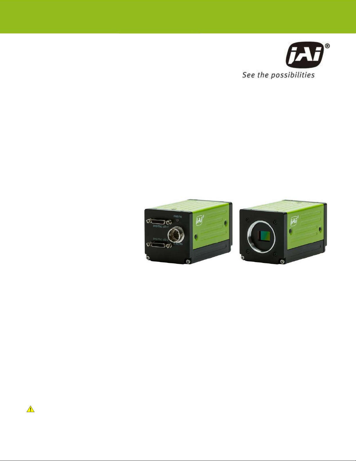
AP-1600T-PMCL | AP-3200T-PMCL | User Manual (Ver. 2.0) Notice/Warranty
- 7 -
Notice/Warranty
Notice
The material contained in this manual consists of information that is proprietary to JAI Ltd., Japan, and
may only be used by the purchasers of the product. JAI Ltd., Japan makes no warranty for the use of
its product and assumes no responsibility for any errors which may appear or for damages resulting
from the use of the information contained herein. JAI Ltd., Japan reserves the right to make changes
without notice.
Company and product names mentioned in this manual are trademarks or registered trademarks of
their respective owners.
Warranty
For information about the warranty, please contact your factory representative.
Certifications
CE Compliance
As defined by the Directive 2004/108/EC of the European Parliament and of the Council, EMC
(Electromagnetic compatibility), JAI Ltd., Japan declares that AP-1600T-PMCL and AP-3200T-PMCL
comply with the following provisions applying to their standards.
EN 61000-6-3 (Generic emission standard part 1)
EN 61000-6-2 (Generic immunity standard part 1)
FCC
This equipment has been tested and found to comply with the limits for a Class B digital device,
pursuant to Part 15 of the FCC Rules. These limits are designed to provide reasonable protection
against harmful interference in a residential installation. This equipment generates, uses and can
radiate radio frequency energy and, if not installed and used in accordance with the instructions, may
cause harmful interference to radio communications. However, there is no guarantee that interference
will not occur in a particular installation. If this equipment does cause harmful interference to radio or
television reception, which can be determined by turning the equipment off and on, the user is
encouraged to try to correct the interference by one or more of the following measures:
lReorient or relocate the receiving antenna.
lIncrease the separation between the equipment and receiver.