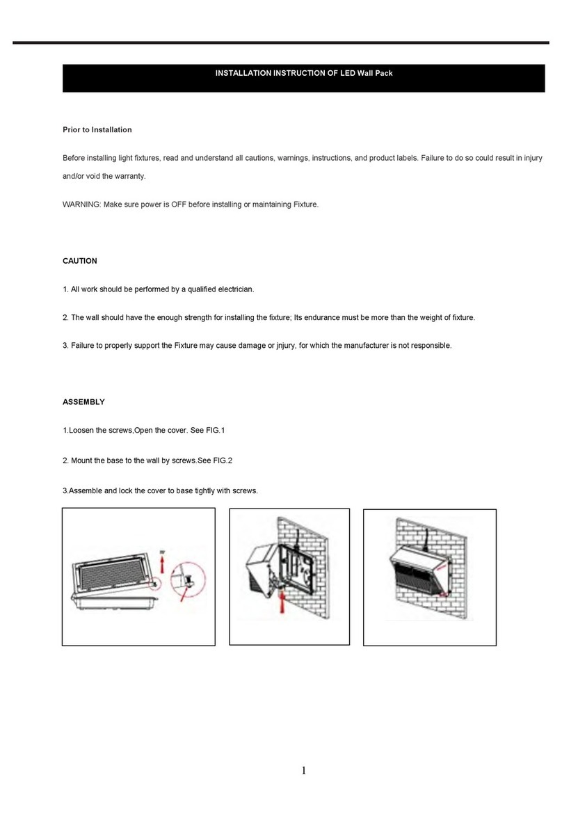
PLT WPM45UNV5KD User manual
Other PLT Outdoor Light manuals
Popular Outdoor Light manuals by other brands

Kichler Lighting
Kichler Lighting HELEN 37536 instructions

Thorn
Thorn OXANE L installation instructions

esotec
esotec Solar Globe Light multicolor 20 operating instructions

mitzi
mitzi HL200201 ELLIS Assembly and mounting instructions

HEPER
HEPER TILA S AFX 3 Module Installation & maintenance instructions

Designplan
Designplan TRON 180 installation instructions

BEGA
BEGA 84 253 Installation and technical information

HEPER
HEPER LW8034.003-US Installation & maintenance instructions

HEPER
HEPER MINIMO Installation & maintenance instructions

LIGMAN
LIGMAN BAMBOO 3 installation manual

Maretti
Maretti TUBE CUBE WALL 14.4998.04 quick start guide

Maxim Lighting
Maxim Lighting Carriage House VX 40428WGOB installation instructions


