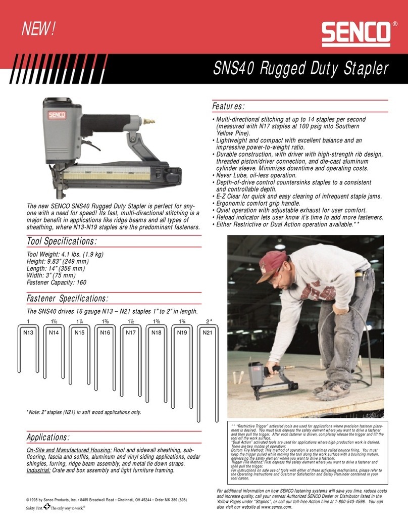
PNI 461 User manual

OwnersManual
Model461
18 Gauge
Flooring Stapler
CAUTION -Read important safety instructions AND operation instructions, BEFORE
operating your Model 461 18 Gauge Flooring Stapler.
Your new Model 461 18 Gauge Flooring Stapler is a quality-built machine, capable of
dependable performance throughout its lifetime. To take full advantage of these capabilities
you should thoroughly understand the proper method and technique of its operation. Therefore,
we suggest you read this manual before operating and that you save it for future reference.
FORM P/N 461139 (3/9/2000)

2
Model 461 18 Gauge
Flooring Stapler
Specifications:
•Operating Pressure : 70 –100 psi.
•Fastener length range: 3/8” –1-1/4”
•Magazine capacity: 2 Strips
•Hose fitting: ¼”NPT
•Weight: 2.4 lbs.
Features:
•Light weight & powerful design
•Precise –drives staples at 45 degree angle
every time.
•Easy loading of nails.
Applications:
•For the installation of ¼”, 5/16”, 3/8”
& ½” hardwood laminate flooring.

3
PNI
TOOL AND PARTS WARRANTY
All PNI Products are Computer Aided Designed to provide maximum power and reliability.
The construction methods use the highest Quality standards of material and workmanship.
TOOL AND PARTS WARRANTY:
PNI Products are warranted to be free of defects from workmanship and material for a
period of one year from the date of original purchase (exceptions: rubber o-rings, seals and
driver blades).
A Five-Year Extended Warranty on the Main Body Casting is available (see the
Warranty Registration for details).
This warranty does not apply where:
•The tool has been abused, misused or improperly maintained.
•Alterations have been made to the tool.
•Repairs have been attempted by others or the use of nonconforming parts.
•The tool has suffered any physical damage arising from the use of the wrong
fasteners.
•Repairs are required because of normal wear and tear.
In no event shall PNI be liable for any indirect, incidental or consequential damage from
the sale or use of the product. This disclaimer applies both during and after the term of
warranty.
This is the only warranty and our company makes no warranties, express or implied,
including merchantability and fitness for a particular purpose, after the one-year term of this
warranty.
Should any trouble develop during this one-year period and/or the Extended Main Body
Casting Warranty, return the complete tool, freight prepaid, to the original place of purchase or
to the PNI factory. If inspection shows the trouble is caused by defective workmanship or
material, PNI will repair (or at our option, replace) without charge and return prepaid.
This limited warranty gives you specific legal rights, and you may also have other rights
which vary from state to state.
4
Safety Instructions
1. Read this manual and understand all safety instruction before operating the
tool.
2. Never allow the use of any type of flammable gases or oxygen as a power
source for the tool. Use filtered, lubricated, regulated compressed air only.
3. Never use gasoline or other flammable liquids to clean the tool. Vapors in
the tool could be ignited by a spark and explode.
4. Do not exceed maximum permissible operating pressure 110 psi (7.6 bar).
5. Disconnect the tool from air supply before clearing jams, servicing,
adjusting, and during non-operation.
6. Do not keep the trigger pulled on contact safety mechanism when carrying
or holding the tool. Never carry the tool by the hose or pull the hose to
move the tool.
7. At the workplace, always wear the protective equipment such as Z37.1
safety glasses ear and head protection.
8. Do not use a check valve or any other fitting which allows air to remain in
the tool.
9. Never point any operational fastener driving tool at yourself or at any other
person.

5
Lubrication And Maintenance
1. Your tool requires lubrication before you use it for the first time.
2. Disconnect the air supply from the tool before lubricating.
3. Turn the tool so the inlet is facing up and put one drop of high speed spindle
oil, UNOCAL RX22, or 3-IN-1 oil into air inlet. Never use detergent oil or
additives. Operate the tool briefly after adding oil.
4. Wipe off excessive oil at the exhaust. Excessive oil will damage
O-rings of tool. If in-line oiler is used, manual lubrication through the air inlet
is not required on a daily basis.
Compressed Air System And Connections
THE FOLLOWING ILLUSTRATION SHOWS THE CORRECT MODE OF CONNECTION TO THE
COMPRESSED AIR SYSTEM WHICH WILL INCREASE THE EFFICIENCY AND USEFUL LIFE OF THE
TOOL.
Many air tool users find it convenient to use oiler to help provide oil circulation through
tool and increase the efficiency and useful life of the tool. Check oil level in the oiler
daily.
Many air, tool users find it convenient to use a filter to remove liquid and impurities
which can rust or wear internal parts of the tool. A filter also increase the efficiency and
life of the tool. The filter must be checked on a daily basis and if necessary drained.
For better performance, install a 3/8” quick connector (1/4” NPT thread) with an inside
diameter of .315” on your tool and a 3/8” quick coupler on the air hose.

6
Contact Safety Mechanism
CHECKING OPERATION OF CONTACT SAFETY MECHANISM
1. Disconnect the air supply from the tool.
2. Empty the magazine.
3. Make sure the trigger and contact safety mechanism move up and down without
any sticking.
4. Connect air supply to the tool.
5. Depress the contact safety mechanism against the workpiece without pulling the
trigger. The tool must not cycle. Never use the tool if a cycle occurs.
6. Hold the tool clear of the workplace. The contact safety mechanism should return
to its original down position. Pull the trigger. The tool must not cycle. Never use
the tool if a cycle occurs.
7. Depress the contact safety mechanism again the workpiece and pull the trigger, the
tool must cycle.
OPERATING A CONTACT SAFETY TOOL
1. The operator requires finger to be off the trigger and the nose of the tool to be
placed on the workpiece.
2. The contact safety mechanism is then depressed against the workpiece and the
trigger is pulled to drive a fastener.
3. The trigger is released after each fastener is driven.
4. Move the tool to the next location and the above procedure repeated.

7
Filling The Magazine
1. Disconnect air hose.
2. Depress the magazine latch. Pull back on the magazine cover.
3. Insert a stick of fasteners into the magazine. Make sure the
pointed ends of the fasteners are resting on the bottom edge of
the magazine.
4. Push the magazine cover forward until the latch catches.

8
OPERATING THE TOOL
PROTECT YOUR EYES AND EARS. WEAR SAFETY GLASSES WITH
SIDE SHIELDS (MUST COMPLY WITH ANSI Z87.1). WEAR HEARING
PROTECTION. EMPLOYERS AND USERS ARE RESPONSIBLE FOR
ENSURING THE USER OR ANYONE NEAR THE TOOL WEAR THIS
SAFETY PROTECTION.
NOTE: CHECK AND REPLACE ANY DAMAGED OR WORN COMPONENTS
ON THE TOOL. THE SAFETY WARNING LABELS ON THE TOOL
MUST ALSO BE REPLACED IF THEY ARE NOT LEGIBLE.
1. Add a few drops of UNOCAL RX22 or 3-IN-1 oil into the air inlet.
2. Install a quick connect fitting to the tool.
3. Connect the tool to an air compressor using a 3/8" I.D. hose. Make sure
the magazine must be empty of all fasteners and the hose has a rated
working pressure exceeding 200 psi (13.8 bar) and a female quick coupler.
4. Regulate the air pressure to obtain 85 psi (5.9 bar) at the tool. Check the
operation of the contact safety mechanism following the instructions in this
manual.
5. Insert fasteners into your tool following the instructions of loading the tool.
6. Reconnect the air hose to the tool.
7. Test for proper fastener penetration by driving fasteners into a piece of
wood. If the fasteners do not achieve the desired penetration, regulate the
air pressure to a higher setting until the desired penetration is achieved. Do
not exceed 100 psi (6.9 bar) at tool.

9
Clearing A Jam From The Tool
DISCONNECT THE TOOL FROM AIR COMPRESSOR BEFORE ADJUSTING.
CLEARING JAMS. SERVICING, RELOCATING AND DURING NON-
OPERATION.
Fastener jammed inside magazine:
1. Disconnect tool from air supply.
2. Press down on latch and pull back on magazine.
3. Remove jammed fastener and push magazine cover forward until latch
catches.
Fastener jammed in fastener discharge area:
Fig. 1 1. Disconnect tool from air supply.
2. If need, remove 2 screws from nose door and open the nose door.
3. Grab jammed fastener with pliers and remove. (See Fig. 1)
4. Close the nose door and install 2 screws. Check the operation of the contact
safety mechanism following the instructions in this manual.
Cleaning The Tool
NEVER USE GASOLINE OR OTHER FLAMMABLE LIQUIDS TO CLEAN THE
TOOL. VAPORS IN THE TOOL WILL IGNITE BY A SPARK AND CAUSE THE
TOOL TO EXPLODE AND RESULT IN DEATH OR SERIOUS PERSONAL
INJURY.
SOLVENTS USED TO CLEAN THE NOSE OF THE TOOL AND CONTACT
SAFETY MECHANISM MAY CAUSE BUILDUP TO BE ACCELERATED IF
NOT DRY. MAKE SURE TO DRY THE TOOL THOROUGHLY AFTER
CLEANING AND BEFORE OPERATING THE TOOL AGAIN.
1. Disconnect the air supply from the tool.
2. Remove tar buildup with kerosene #2 fuel oil or diesel fuel. Do not allow solvent
to get into the cylinder or damage may occur. Dry off the tool completely before
use.

10

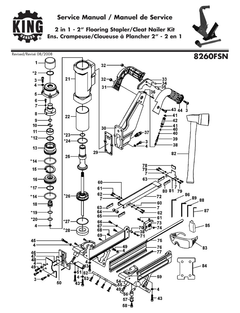
11
ITEM
DESCRIPTION PART
NO.
1SCREW -SOC BUTT. HD 46141
2DEFLECTOR 46109
3SCREW -SOC HEAD 46159
4SEAL 46016
5WASHER -SPRING 46065
6CAP 46119
7SEAL 46101
8 O-RING 46147
9 GASKET -CAP 46124
10 SPRING 46103
11 VALVE -PISTON HEAD 46120
12 O-RING 46150
13 COLLAR 46125
14 C-RING 46123
15 O-RING 46153
16 O-RING -PISTON 46122
17 E-RING 46051
18 PISTON RAM ASSEMBLY 46135
19 O-RING 46148
20 GUIDE -RAM 46102
21 SPACER -CYLINDER 46117
22 O-RING 46149
23 O-RING 46151
24 E-RING 46145
25 SAFETY 46136
26 CYLINDER 46116
27 FOOT -REAR 46138
28 SCREW -SOC HEAD 46067
29 SCREW -SOC HEAD 46157
30 PIN –SPRING 46144
31 COVER-QUICK RELEASE 46126
32 BUMPER 46118
33 NUT -LOCK 46142
ITEM
DESCRIPTION PART
NO.
34 CONNECTOR -AIR 46050
35 CAP –END 46121
36 O-RING 46152
37 BODY –GUN 46115
38 TRIGGER -SECONDARY 46104
39 TRIGGER -PRIMARY 46110
40 PIN -SPRING 46143
41 PIN -STEPPED 46111
42 ROD 46112
43 PIN -ROLL 46133
44 MAGAZINE46130
45 NOSE 46139
46 COVER -NOSE B 46114
47 WASHER -SPRING 46064
48 O-RING 46155
49 VALVE -TRIGGER 46106
50 SPRING 46108
51 O-RING 46154
52 STEM -TRIGGER VALVE 46107
53 FRONT FOOT 46137
54 O-RING 46146
55 GUIDE -TRIGGER VALVE
46105
56 SPRING 46113
57 BUTTON 46134
58 PLATE 46129
59 ROLLING ELEMENT 46132
60 SPRING -ROLLER 46131
61 PUSHER 46127
62 COVER-NOSE ASSEMBLY
46140
63 BRACKET -LATCH 46128
64 SCREW -SOC HEAD 46156
65 SCREW -SOC HEAD 46158

12
Troubleshooting
Problem Cause Remedy
Air leaking at trigger valve area.
O-rings in trigger valve housing
are damaged.
O-rings must be replaced &
operation of contact safety trip
mechanism must be checked.
Air is leaking between housing and nose.
Loose screws in housing.
Damaged O-rings.
Damage to Bumper
Screws need to be tightened.
O-rings must be replaced.
Bumper needs to be replaced
Air is leaking between housing and cap
assembly.
Loose screws.
Damaged Seal.
Screws need to be tightened.
Seal needs to be replaced.
Tool skips driving Fastener.
Worn Bumper.
Dirt in nose.
Dirt or damage prevents
fasteners from moving freely in
the magazine.
Inadequate air flow to tool.
Worn O-rings on Piston or lack
of lubrication.
Damaged O-rings on Trigger
Valve.
Air leaks.
Cap Seal is leaking.
Bumper needs to be replaced.
Clean.
Magazine needs to be cleaned.
Fitting house or air compressor
needs to be checked.
O-ring needs to be replaced.
Lubricate.
O-ring needs to be replaced.
Screws and fittings need to be
tightened.
Seal needs to be replaced.
Tool runs slow or has loss of power.
Tool not lubricated sufficiently.
Broken Spring in Cap assembly.
Exhaust port in Cap is blocked.
Tool needs to be lubricated.
Spring needs to be replaced.
Damaged internal parts, need to be
replaced.
Fasteners are jammed in Tool
Driver Guide worn or damaged.
Driver is damaged.
Fasteners are not correct size.
Fasteners are bent.
Magazine or nose screws are
loose.
Replace Driver Guide.
Replace Driver.
Fasteners recommended for tool
must be used.
Replace with undamaged fasteners.
Screw need to be tightened.

13
NOTES
Table of contents
Popular Staple Gun manuals by other brands

haubold
haubold RNC 90 Z operating instructions

Desa
Desa PowerFast 34392 operating instructions

Workzone
Workzone WZEN 20 Operating instructions & user guide

Black & Decker
Black & Decker PowerShot 5700 instruction manual

Arrow
Arrow T37P quick start guide

Schneider Airsystems
Schneider Airsystems KNG 50 SYS Original operating manual