PNY M.2 2280 SSD RGB Heatsink
Product Assembly Guide
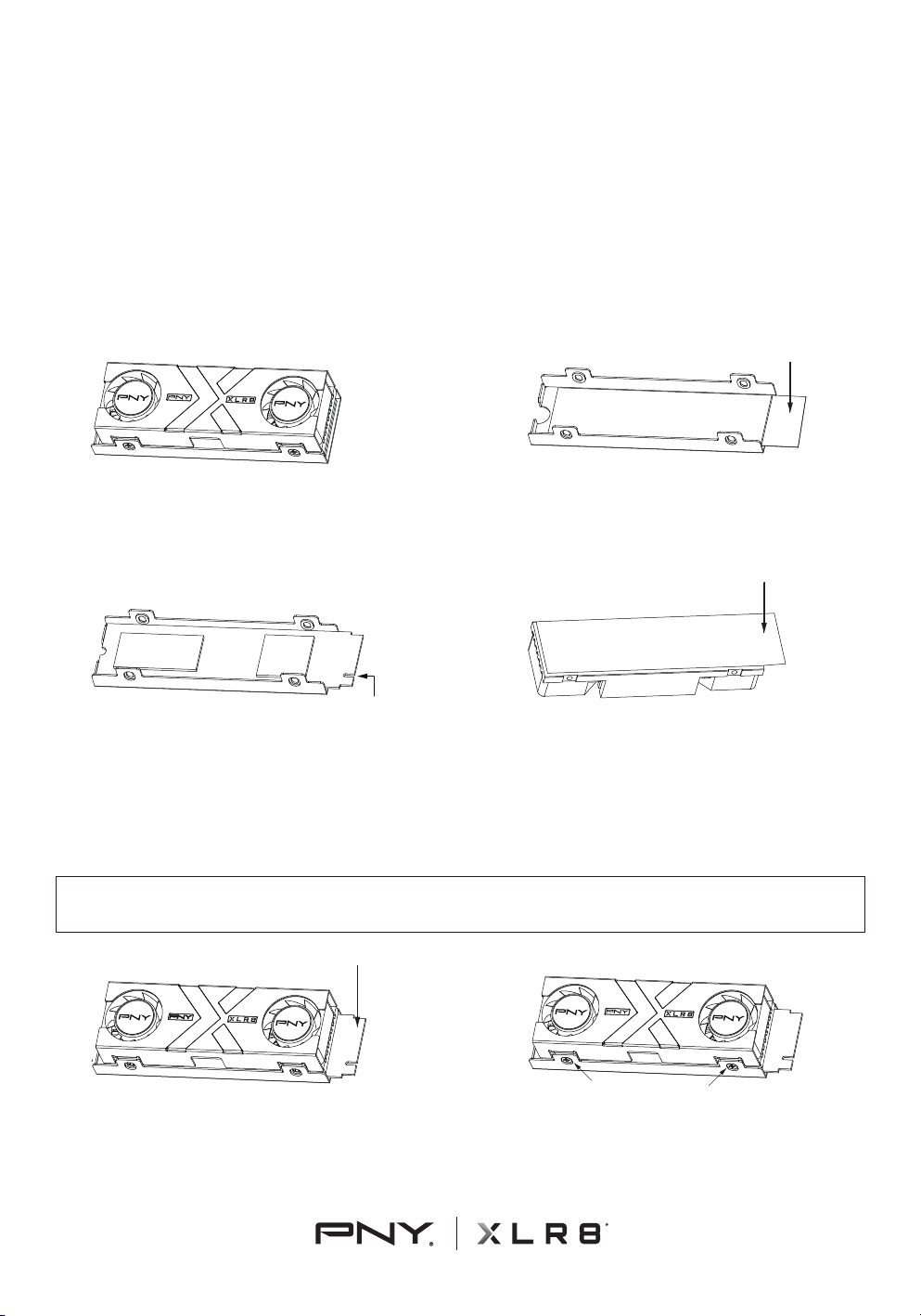
Included Parts - Aluminum base plate with thermal pad,
heatsink with thermal pad, 4x screws
English
ELECTROSTATIC DISCHARGE WARNING:
Electronic components may become damaged by electrostatic discharge (ESD).
Handle all parts with extreme caution to prevent damage, including but not limited
to the Solid State Drive (SSD). Consider learning about and taking ESD protection
measures for your equipment. Before removing components from the antistatic
foam, touch a grounded metal object.
1. Using a Phillips #1 screwdriver, remove the 4x screws holding the heatsink
and base plate together. Save these 4 screws for reassembly later.
2. Remove the protective lm from the thermal pad on the heatsink base plate
exposing adhesive surface. Do not remove the thermal pad itself.
3. Align the SSD screw cutout with the heatsink base plate cutout. Attach the
SSD to the adhesive surface of thermal pad, making sure the cutouts remain
aligned. When looking from above, the PCIe notch should be to the right as
shown in the picture.
4. Remove the protective lm from the thermal pad on the heatsink. Do not
remove thermal pad itself. Align the heatsink’s screw holes with the base plate.
IMPORTANT:For best results, remove the top decorative label from the SSD
so that the controller and ash are exposed. Ensure SSD orientation is correct
for motherboard installation.
5. When placing the heatsink on top of the SSD, ensure that the fan cable is on
the same side as the PCIe connector notch of the SSD. Then align the heatsink’s
screw holes with the base plate. Press the heatsink down until the screw holes
are in alignment using even, gentle pressure.
6. Fasten the heatsink to the heatsink base plate with the 4x screws from Step 1
using a Phillips #1 screwdriver.
PNY M.2 SSD RGB 散熱器組裝
操作規範
組成部分 - 鋁底板(含導熱膠片),風扇模組(含導熱膠片),4顆螺絲
靜電放電警告:靜電放電 (ESD) 可能造成固態硬碟 (SSD)及其他電子元件受損,
請妥善地處理以防止損壞。請詳閱並理解可能的風險並為您的設備採取
ESD 保護措施,從抗靜電泡綿中取出物件之前,請觸摸接地的金屬物體
以防止靜電產生。
1. 用合適的螺絲起子將鋁底板和風扇模組拆開並保管好拆下來的4顆螺絲。
2. 移除位於鋁底板上的導熱膠PE膜。請勿移除導熱膠片。
3. 將SSD上的螺絲孔(半圓缺孔)與鋁底板的缺口對齊貼平。
當您由上方往下看時,SSD的金手指會在右手邊(如圖)。
4. 移除位於風扇模組上的導熱膠PE膜。(請勿移除導熱膠片。)
對齊風扇模組與鋁底板上的螺絲孔。
重點提醒:為了獲得最佳散熱效果,請撕下固態硬碟(SSD)表面的標籤貼紙,
將控制晶片和快閃記憶體直接接觸導熱膠片,並確認固態硬碟以正確的方向
安裝至主機板插槽上。
5. 安裝風扇模組時,請注意風扇連接線的方向與金手指短邊缺口同側。
對齊風扇模組與鋁底板上的螺絲孔後,向下輕壓即可裝上風扇模組。
6. 用適合的螺絲起子將鋁底板和風扇模組鎖好 ( 第一步拆下來的 4 顆螺絲)。
PNY M.2 SSD 灯光散热器组装
操作规范
组成部分 - 铝底板(含导热胶片),风扇模块(含导热胶片),4颗螺丝
静电放电警告:静电放电 (ESD) 可能造成固态硬盘 (SSD)及其他电子组件受损,
请妥善地处理以防止损坏。请详阅并理解可能的风险并为您的设备采取
ESD 保护措施,从抗静电泡绵中取出对象之前,请触摸接地的金属物体
以防止静电产生。
1. 用适合的螺丝刀将铝底板和风扇模块拆开并保管好拆下来的4颗螺丝。
2. 移除位于铝底板上的导热胶PE膜。请勿移除导热胶片。
3. 将SSD上的螺丝孔(半圆缺孔)与铝底板的缺口对齐贴平。
当您由上方往下看时, SSD的金手指会在右手边(如图)。
4. 移除位于风扇模组上的导热胶PE膜。 (请勿移除导热胶片。)
对齐风扇模组与铝底板上的螺丝孔。
重点提醒:为了获得最佳散热效果,请撕下固态硬盘(SSD)表面的卷标贴纸,
将控制芯片和闪存直接接触散热贴片,并确认固态硬盘以正确的方向安装至
主板插槽上。
5. 安装风扇模块时,请注意风扇连接线的方向与金手指短边缺口同侧。
对齐风扇模块与铝底板上的螺丝孔后,向下轻压即可装上风扇模组。
6. 用适合的螺丝刀将铝底板和风扇模块锁好 ( 第一步拆下来的 4 颗螺丝)。
PNY Dissipateur thermique avec
RGB pour SSD M.2 2280
Guide de montage
Pièces incluses: Plaque de support en aluminium avec pad thermique, dissipateur
thermique avec pad thermique, 4 vis
French
AVERTISSEMENT DE DÉCHARGE ÉLECTROSTATIQUE :
Les composants électroniques peuvent être endommagés par une décharge
électrostatique (ESD). Manipulez toutes les pièces avec une extrême prudence pour
éviter tout dommage, y compris, mais sans s'y limiter, sur le disque SSD.
Pensez à vous renseigner et à prendre des mesures de protection pour votre
équipement contre les décharges électrostatiques. Avant de retirer les composants
de la mousse antistatique, touchez un objet métallique relié à la terre.
1. À l'aide d'un tournevis Phillips nº1, retirez les 4 vis qui maintiennent le
dissipateur thermique et la plaque de support. Conservez ces 4 vis pour les
remonter plus tard.
2. Retirez le lm protecteur du pad thermique sur la plaque de support du
dissipateur thermique en exposant la surface adhésive. Ne retirez pas le pad
thermique lui-même.
3. Alignez la découpe de la vis SSD avec la découpe de la plaque de support du
dissipateur thermique. Fixez le SSD à la surface adhésive du pad thermique en
vous assurant que les découpes restent alignées. Vue d'en haut, l'encoche PCIe
doit se trouver à droite, comme indiqué sur l'image.
4. Retirez le lm protecteur du pad thermique sur le dissipateur thermique. Ne
retirez pas le pad thermique lui-même. Alignez les trous de vis du dissipateur
thermique avec la plaque de support.
IMPORTANT : Pour de meilleurs résultats, retirez l'étiquette décorative
supérieure du SSD an que le contrôleur et la mémoire ash soient exposés.
Assurez-vous que l'orientation du SSD est correcte pour l'installation de la
carte mère.
5. Lorsque vous placez le dissipateur thermique sur le SSD, assurez-vous que le
câble du ventilateur se trouve du même côté que l'encoche du connecteur PCIe
du SSD. Alignez ensuite les trous de vis du dissipateur avec la plaque de
support. Appuyez sur le dissipateur jusqu'à ce que les trous de vis soient alignés
en exerçant une pression douce et uniforme.
6. Fixez le dissipateur thermique à la plaque de support du dissipateur avec les 4
vis de l'étape 1 à l'aide d'un tournevis Phillips nº1.
PNY Disipador con RGB para
SSD M.2 2280
Guía de montaje
Piezas incluidas: placa base de aluminio con pad térmico, disipador térmico con
pad térmico, 4 tornillos
Spanish
ADVERTENCIA SOBRE DESCARGAS ELECTROSTÁTICAS :
Los componentes electrónicos pueden resultar dañados por una descarga
electrostática (ESD). Manipule todas las piezas con extrema precaución para evitar
daños, incluidos, entre otros, de la unidad de estado sólido (SSD). Considere la
posibilidad de informarse y tomar medidas de protección ESD para su equipo.
Antes de retirar los componentes de la espuma antiestática, toque un objeto
metálico conectado a tierra.
1. Con un destornillador Phillips nº1, quite los 4 tornillos que sujetan el disipador
de calor y la placa base. Guarde estos 4 tornillos para volver a montarlos más
tarde.
2. Retire la película protectora del pad térmico en la placa base del disipador,
dejando al descubierto la supercie adhesiva. No quite el pad térmico en sí.
3. Alinee el recorte del tornillo SSD con el recorte de la placa base del disipador
térmico. Coloca la SSD a la supercie adhesiva del pad térmico, asegurándose
de que los recortes permanezcan alineados. Mirando desde arriba, la muesca
PCIe debe estar a la derecha como se muestra en la imagen.
4. Retire la película protectora del pad térmico del disipador de calor. No quite el
pad térmico en sí. Alinee los oricios de los tornillos del disipador térmico con la
placa base.
IMPORTANTE : Para obtener los mejores resultados, retire la etiqueta
decorativa superior de la SSD para que el controlador y la memoria ash
queden expuestos. Asegúrese de que la orientación del SSD sea la correcta
para la instalación de la placa base.
5. Cuando coloque el disipador de calor encima de la SSD, asegúrese de que el
cable del ventilador está en el mismo lado que la muesca del conector PCIe de la
SSD. Luego, alinee los oricios de los tornillos del disipador térmico con la placa
base. Presione el disipador hasta que los oricios de los tornillos queden
alineados ejerciendo una presión suave y uniforme.
6. Fije el disipador de calor a la placa base del disipador de calor con los 4
tornillos del paso 1 con un destornillador Phillips nº1.
PNY M.2 2280 SSD-Kühlkörper
Montageanleitung
Enthaltene Teile: Aluminiumgrundplatte mit Wärmeleitpad, Kühlkörper mit
Wärmeleitpad, 4x Schrauben
German
WARNUNG VOR ELEKTROSTATISCHER ENTLADUNG:
Elektronische Komponenten können durch elektrostatische Entladung beschädigt
werden. Behandle alle Teile mit äußerster Vorsicht, um Schäden zu vermeiden,
einschließlich, aber nicht beschränkt auf das Solid State Drive (SSD). Erwäge,
dich über ESD-Schutzmaßnahmen für deine Ausrüstung zu informieren und
diese zu ergreifen. Bevor Sie Komponenten aus dem antistatischen Schaumstoff
entfernen, berühren Sie einen geerdeten Metallgegenstand.
1. Entferne mit einem Kreuzschlitzschraubendreher Nr. 1 die 4 -Schrauben, die
den Kühlkörper und die Grundplatte zusammenhalten. Hebe diese 4 Schrauben
für den späteren Wiederzusammenbau auf.
2. Entferne die Schutzfolie vom Wärmeleitpad auf der Grundplatte des
Kühlkörpers und lege die Klebeäche frei. Entferne nicht das Wärmeleitpad
selbst.
3. Richte die Aussparung für die SSD-Schraube an der Aussparung für die
Grundplatte des Kühlkörpers aus. Befestige die SSD auf der Klebeäche des
Wärmeleitpads und achte darauf, dass die Aussparungen aneinander
ausgerichtet bleiben. Von oben betrachtet sollte sich die PCIe-Kerbe rechts
benden, wie im Bild gezeigt.
4. Entferne die Schutzfolie von dem Wärmeleitpad auf dem Kühlkörper. Entferne
nicht das Wärmeleitpad selbst. Richten Sie die Schraubenlöcher des Kühlkörpers
an der Grundplatte aus.
WICHTIG : Die besten Ergebnisse erzielst du, wenn du den oberen Aufkleber
von der SSD entfernst, damit der Controller und der Flash-Speicher sichtbar
werden. Achte darauf, dass die SSD für den Einbau auf dem Motherboard
richtig ausgerichtet ist.
5. Achten Sie beim Aufsetzen des Kühlkörpers auf die SSD darauf, dass sich das
Lüfterkabel auf der gleichen Seite bendet wie die PCIe-Anschlusskerbe der
SSD. Richten Sie dann die Schraubenlöcher des Kühlkörpers an der Grundplatte
aus. Drücken Sie den Kühlkörper mit gleichmäßigem, leichtem Druck nach unten,
bis die Schraubenlöcher in einer Linie liegen.
6. befestige den Kühlkörper mit den 4x -Schrauben aus Schritt 1 mit einem
Kreuzschlitzschraubendreher Nr.1 an der Grundplatte des Kühlkörpers.
PNY M.2 2280 SSD Heatsink
Instrukcja montażu
Elementy zestawu: aluminiowa podstawa ze spoiwem termicznym, radiator ze
spoiwem termicznym, 4x śruby .
Polish
OSTRZEŻENIE PRZED WYŁADOWANIAMI ELEKTROSTATYCZNYMI:
Elementy elektroniczne mogązostaćuszkodzone przez wyładowania elektrostatyczne
(z ang. ESD). Ze wszystkimi komponentami należy obchodzićsięz jak najwyższą
ostrożnością, aby zapobiec ich uszkodzeniu, włączając w to dysk SSD. Zaleca się
zapoznanie sięze środkami ochrony przed wyładowaniami elektrostatycznymi (ESD)
i podjęcie takich środków. Przed wyjęciem komponentów z pianki antystatycznej,
należy dotknąć uziemionego, metalowego przedmiotu.
1. Używając śrubokręta krzyżakowego, odkręć 4 śruby utrzymujące aluminiową
podstawęi radiator ze sobą. Zachowaj odkręcone śruby do późniejszego
ponownego użycia.
2. Zdejmij folięochronnąze spoiwa termicznego na podstawie radiatora, aby
odsłonićsamoprzylepnąpowierzchnięspoiwa termicznego. Uważaj przy tym, aby
nie zdjąć spoiwa termicznego.
3. Wyrównaj wycięcie na śrubęznajdujące sięna dysku SSD z tym na bazie
radiatora.Przymocuj dysk SSD do samoprzylepnej powierzchni spoiwa
termicznego, upewniając się, że wycięcia sądo siebie dopasowane. Patrząc od
góry, wycięcie PCIe powinno znajdowaćsiępo prawej stronie, jak pokazano na
rysunku.
4. Zdejmij folięochronnąze spoiwa termicznego na radiatorze. Uważaj przy tym,
aby nie zdjąć spoiwa termicznego. Wyrównaj otwory na śruby radiatora z płytą
bazową.
WAŻNE : Dla najlepszego chłodzenia, zdejmij naklejkędekoracyjnąz dysku
SSD tak, aby odsłonićmoduły pamięci oraz kontroler. Upewnij się, że
orientacja dysku SSD jest odpowiednia do instalacji na płycie głównej.
5. Umieszczając radiator na dysku SSD, upewnij się, że kabel wentylatora
znajduje siępo tej samej stronie, co wycięcie złącza PCIe dysku SSD. Następnie
wyrównaj otwory na śruby radiatora z płytąbazową. Dociskaj radiator w dół, aż
otwory na śruby zostanąwyrównane, używając równomiernego, delikatnego
nacisku.
6. Używając śrubokręta krzyżakowego, przymocuj radiator do aluminiowej
podstawy radiatora. Wykorzystaj do tego 4 śruby, które pozostały z pierwszego
kroku.pierwszego kroku.
PNY Dissipatore per SSD
M.2 2280 Guida al montaggio
Parti incluse: Piastra di base in alluminio con pad termico, dissipatore di calore con
pad termico, 4 viti
Italian
AVVERTENZA SULLE SCARICHE ELETTROSTATICHE:
i componenti elettronici possono essere danneggiati dalle scariche elettrostatiche
(ESD). Maneggiare tutte le parti con estrema cautela per evitare danni, incluso,
ma non solo, sull'unità a stato solido (SSD). Prendi in considerazione la possibilità
di conoscere e adottare misure di protezione ESD per le sue apparecchiature.
Prima di rimuovere i componenti dalla schiuma antistatica, toccare un oggetto
metallico collegato a terra.
1. Utilizzando un cacciavite Phillips nº1, rimuovere le 4 viti che tengono insieme il
dissipatore di calore e la piastra di base. Conserva queste 4 viti per il rimontaggio
dopo.
2. Rimuovere la pellicola protettiva dal pad termico sulla piastra di base del
dissipatore di calore, esponendo la supercie adesiva. Non rimuovere il pad
termico stesso.
3. Allineare l'intaglio della vite dell'SSD con l'intaglio della piastra di base del
dissipatore. Attacca l'SSD alla supercie adesiva del pad termico, assicurandovi
che i ritagli rimangano allineati. Guardando dall'alto, la tacca PCIe dovrebbe
trovarsi a destra, come mostrato nell'immagine.
4. Rimuovere la pellicola protettiva dal pad termico sul dissipatore di calore. Non
rimuovere il pad termico stesso. Allineare i fori delle viti del dissipatore con la
piastra di base.
IMPORTANTE: per ottenere i migliori risultati, rimuovere l'etichetta
decorativa superiore dell'SSD in modo che il controller e la memoria ash
siano esposti. Assicurarsi che l'orientamento dell'SSD sia corretto per
l'installazione della scheda madre.
5. Quando si posiziona il dissipatore di calore sopra l'unità SSD, assicurarsi che il
cavo della ventola sia sullo stesso lato della tacca del connettore PCIe dell'unità
SSD. Dopo, allineare i fori delle viti del dissipatore con la piastra di base. Premere
il dissipatore verso il basso nché i fori delle viti non sono allineati, esercitando
una pressione uniforme e delicata.
6. Fissare il dissipatore di calore alla piastra di base del dissipatore con le 4 viti
del passo 1 utilizzando un cacciavite Phillips nº1.
PNY Dissipador de calor para
SSD M.2 2280 Guia de montagem
Peças incluídas: placa de base de alumínio com adesivo térmico, dissipador de
calor com adesivo térmico, 4 parafusos
Portuguese
ADVERTÊNCIA DE DESCARGA ELETROSTÁTICA:
Os componentes eletrônicos podem ser danicados por descarga eletrostática
(ESD). Manuseie todas as peças com extremo cuidado para evitar danos,
incluindo, entre outros, a unidade de estado sólido (SSD). Considere aprender e
tomar medidas de proteção ESD para o seu equipamento. Antes de remover os
componentes da espuma antiestática, toque em um objeto de metal aterrado.
1. Com uma chave de fenda Phillips nº1, remova os 4 parafusos que prendem o
dissipador de calor e a placa de base. Guarde esses 4 parafusos para que você
possa montá-los novamente mais tarde.
2. Remover a película protetora do pad térmico da placa de base do dissipador
de calor, expondo a superfície adesiva. Não remove o próprio pad térmico.
3.Alinhe o recorte do parafuso da SSD com o recorte da placa de base do
dissipador de calor. Fixe a SSD na superfície adesiva do pad térmico,
certicando-se de que os recortes permaneçam alinhados. Quando visto de
cima, o entalhe PCIe deve estar à direita, como mostra a imagem.
4. Remover a película protetora da almofada térmica no dissipador de calor. Não
remova o próprio pad térmico. Alinhe os orifícios dos parafusos do dissipador de
calor com a placa de base.
IMPORTANTE: Para obter melhores resultados, remova a etiqueta decorativa
superior do SSD para que o controlador e a memória ash quem expostos.
Certique-se de que a orientação do SSD esteja correta para a instalação da
placa-mãe.
5. Quando colocar o dissipador de calor em cima do SSD, certique-se de que o
cabo do ventilador está do mesmo lado que o entalhe do conetor PCIe do SSD.
Em seguida, alinhe os orifícios dos parafusos do dissipador de calor com a placa
de base. Pressione o dissipador de calor para baixo até que os orifícios dos
parafusos estejam alinhados, utilizando uma pressão suave e uniforme.
6. Fixe o dissipador de calor a placa de base do dissipador de calor com os 4
parafusos do Passo 1, utilizando uma chave de fendas Phillips nº1.
Note: Fans will not spin until drive reaches around 43°C.
Remarque : les ventilateurs ne tourneront pas tant que le SSD n'aura pas atteint
une température d'environ 43°C.
注意: 當溫度達到43°C時風扇才會轉動 注意: 当温度达到43°C时风扇才会转动。
Nota: Los ventiladores no girarán hasta que la unidad alcance alrededor de 43 °C.
Hinweis: Die Lüfter drehen sich erst, wenn das Laufwerk eine Temperatur
von etwa 43°C erreicht.
Uwaga: Wentylatory nie będąsięobracać, dopóki napęd nie osiągnie około 43°C. Nota: le ventole non gireranno no a quando l'unità non raggiungerà circa 43°C. Observação: os ventiladores não irão girar até que o drive atinja cerca de 43°C.
繁中 (Traditional Chinese) 簡中 (Simplified Chinese)