Polar Ware STOELTING U431 User manual

Model U431 (Serial #0 thru 17977)
OWNER'S MANUAL
Manual No. 513568 Dec. 2002, Rev. 5


Need Parts or Service?
We stock the parts you need.
Our Technicians are factory
trained and are certified in the
Stoelting Technicare program.
Model No.: _______________________
Serial No.: _______________________
Purchase Date: ____________________
Start-Up Date:____________________
CALL
Distributor: _________________________
Phone No.: _________________________
(fill in or affix label)


STOELTING, LLC Tele: 920-894-2293
502 Hwy 67
Kiel, WI 53042-1600 Fax: 920-894-7029
STOELTING®OWNER'S MANUAL
FOR
MODEL U431
CAB MODEL SOFT-SERVE PRESSURIZED FREEZER
This manual provides basic information about the freezer. Instructions and suggestions are given
covering its basic operation and care.
Theillustrationsandspecificationsarenotbindingindetail. Wereservetherighttomakechanges
atanytimewithoutnotice,tothefreezeranditscomponents,withoutincurringanyobligationtomodify
orprovide newparts forfreezers builtprior todate ofchange.
DONOTATTEMPTtooperatethefreezeruntilinstructionsandsafetyprecautionsinthismanualare
readcompletelyandarethoroughlyunderstood. Ifproblemsdeveloporquestionsariseinconnection
withinstallation,operationorservicingofthefreezer,contactthecompanyatthelocationlistedbelow.


TABLE OF CONTENTS
Section 1 .............................................................................................................. 1
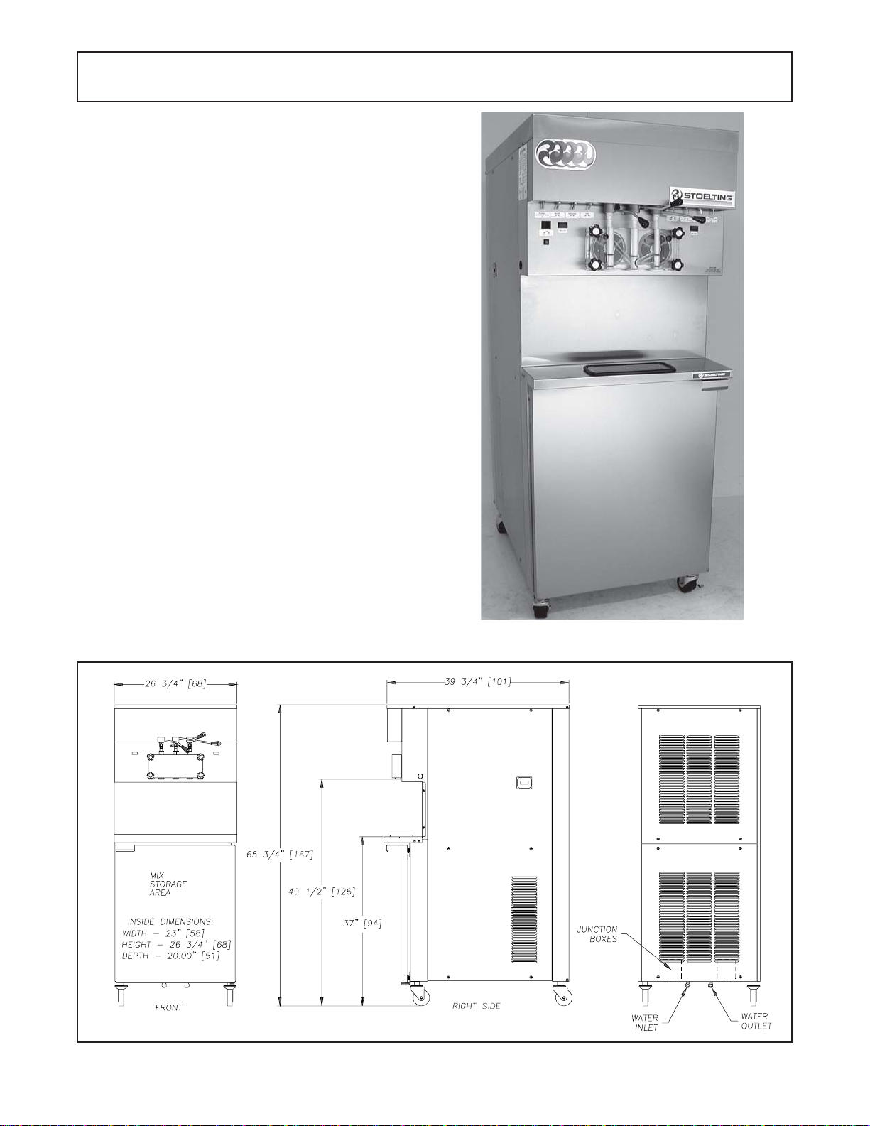
1.1 Description.............................................................................................. 1
1.2 Specifications.......................................................................................... 2
Section 2 .............................................................................................................. 3
2.1 SafetyPrecautions .................................................................................. 3
2.2 Shipment &Transit .................................................................................. 4
2.3 FreezerInstallation................................................................................... 4
2.4 Installing PermanentWiring...................................................................... 4
2.5 Mix Pump ................................................................................................ 5
Section 3 .............................................................................................................. 9
3.1 SafetyPrecautions .................................................................................. 9
3.2 OperatingControls andIndicators............................................................ 9
3.3 Sanitizing ................................................................................................ 10
3.4 InitialFreeze DownandOperation ........................................................... 11
3.5 MixInformation ........................................................................................ 11
3.6 OperationofMix Pump ............................................................................ 11
3.7 RemovingMix fromthe Freezer ............................................................... 12
3.8 Cleaningthe Freezer ............................................................................... 12
3.9 Disassemblyof Freezer Parts.................................................................. 12
3.10 RoutineCleaning ..................................................................................... 13
3.11 MixPump Cleaning ................................................................................. 14
3.12 SanitizeFreezerParts ............................................................................. 14
3.13 AssemblyofFreezer................................................................................ 14
Section 4 .............................................................................................................. 17
4.1 Freezer Adjustment ................................................................................. 17
4.2 ProductTemperatureAdjustment ............................................................. 17
4.3 OverrunAdjustment ................................................................................. 17
4.4 Mix PumpHoseReposition ..................................................................... 18
4.5 MixPump HoseReplacement.................................................................. 18
4.6 CabTemp.Adjustment............................................................................. 18
4.7 DriveBeltTensionAdjustment.................................................................. 18
4.8 Condenser Cleaning(Air Cooled Freezers) ............................................. 19
4.9 PreventativeMaintenance........................................................................ 19
4.10 ExtendedStorage ................................................................................... 19
4.11 Troubleshooting ....................................................................................... 20
Section 5 .............................................................................................................. 25
5.1 How toOrderReplacement Parts ............................................................ 25
5.2 PartsLists and ReferenceDrawings........................................................ 25

ILLUSTRATIONS
Figure 1 ModelU431 Freezer ..............................................................1
Figure 2 Specifications........................................................................1
Figure 3 Decal Locations.....................................................................3
Figure 4 Water/ElectricalConnections .................................................4
Figure 5 AugerRotation.......................................................................4
Figure 6 MixHoseInstallation...............................................................5
Figure 7 MixPump...............................................................................6
Figure 8 4WayTee .............................................................................7
Figure 9 MixInletTube &ProbeAssy.Clip...........................................7
Figure 10 HoseHolder...........................................................................7
Figure 11 OperatingControls.................................................................9
Figure 12 Air Bleed Valves ....................................................................10
Figure 13 DrainingSanitizer ..................................................................10
Figure 14 MixContainer.........................................................................11
Figure 15 MixPumps.............................................................................12
Figure 16 AugerFlight Wear& FrontAuger SupportBushingWear .......13
Figure 17 FrontDoor Disassembly ........................................................13
Figure 18 AugerFlightRemoval.............................................................13
Figure 19 RearSealRemoval................................................................13
Figure 20 CleaningFeedTube ..............................................................14
Figure 21 CleaningAirTube ..................................................................14
Figure 22 RemovableParts ...................................................................14
Figure 23 RearSeal Lubrication ............................................................14
Figure 24 SpringInstallation...................................................................15
Figure 25 FrontDoorAssembly .............................................................15
Figure 26 Potentiometer ........................................................................17
Figure 27 OverrunAdjustment................................................................17
Figure 28 TemperatureControlCab ......................................................18
Figure 29 BeltAdjustment ......................................................................19

1
SECTION 1
INTRODUCTION
1.1 DESCRIPTION
The Stoelting U431 floor model freezer is pressure fed.
The freezer is equipped with fully automatic controls to
provide a uniform product. The freezer is designed to
operate with almost any type of commercial soft-serve
ornon-dairy mixesavailable,including icemilk, icecream,
yogurt, and frozen dietary desserts.
Thismanual isdesignedto assistqualified personneland
operators in the installation, operation and maintenance
of the Stoelting Model U431 pressure freezer.
Figure 1. Model U431 Freezer
Figure 2. Specification

2
134ULEDOM
SNOISNEMID
)mc761("4/3-56:thgieH)mc101("4/3-93:htpeD)mc86("4/3-62:htdiW
THGIEW
)gk244(etarC/w.sbl579)gk5,914(.sbl529
LACIRTCELE
rewopetarapes2( ).deriuqersecruos
HP3HP1HP3HP1
ediStfeL ediSthgiR ediStfeL ediSthgiR ediStfeL ediSthgiR ediStfeL ediSthgiR
2.118.412.718.022.116.112.716.71spmAgninnuRlatoT 1262136312121313yticapmAtiucriCmuminiM 035354050303545
4rekaerBtiucriC.xaMRCAH 0353540503035454eziSesuFmumixaM
ROSSERPMOC
hcae.H.U.T.B096,11
ROTOMEVIRD
hcaePH2
GNILOOC
.ecnaraelcpot)mc52("01dnaecnaraelcdnuoralla)mc5,7("3s'qer.deloocriaroretaW .sgnittifniarddnaretawTPN)m
m5,21("2/1s'qerdeloocretaW
1.2 SPECIFICATIONS

3
SECTION 2
INSTALLATION INSTRUCTIONS
2.1 SAFETY PRECAUTIONS
WARNING CAUTION
Donotattempt to operatethefreezer until thesafetypre-
cautionsand operatinginstructionsin themanual areread
completely and are thoroughly understood.
Takenoticeofallwarning labelson thefreezer (Fig.3).The
labels have been put there to help you maintain a safe
working environment. The labels have been designed to
withstand washing and cleaning. All labels must remain
legiblefor thelife ofthefreezer.Labels shouldbechecked
periodically to be sure they have not been painted over,
rubbed off, fallen off, and can be recognized as warning
labels.
Ifyouare in needofreplacement labels, indicatethepart
number, type of label, location of label, and quantity re-
quired along with your name and address and mail to:
Stoelting, LLC
Commercial Products
502 Hwy. 67
Kiel, WI 53042
Figure 3. Decal Locations

4
2.2 SHIPMENT AND TRANSIT
The freezer has been assembled, operated, and in-
spected at the factory. Upon arrival at the final destina-
tion, the freezer must be checked for any damage which
may have occurred during final transit.
With the method of packaging used, the equipment
should arrive in excellent condition. THE CARRIER IS
RESPONSIBLE FOR ALL DAMAGE IN TRANSIT,
WHETHER VISIBLE OR CONCEALED. Do not pay the
freight bill until the freezer has been checked for dam-
age. Have the carrier note any visible damage on the
freightbill. If concealeddamageand/or shortageisfound
later advise the carrier within ten days and request in-
spection. The customer must place claim for damage
and/or shortages in shipment with the carrier. Stoelting,
Inc. cannot make any claims against the carrier.
2.3 FREEZER INSTALLATION
WARNING
INSTALLATION MUST BE PERFORMED BY A
QUALIFIED ELECTRICIAN/REFRIGERATION
SPECIALIST. INCORRECT INSTALLATION WILL
VOID THE WARRANTY, AND MAY CAUSE SE-
VERE DAMAGE TO THE MACHINE. MAY
CAUSE PERSONAL INJURY.
Installation of the freezer involves moving the freezer
closetoits permanent location, removingallcrating, set-
ting in place, assembling parts, and cleaning.
A. Uncrate the freezer.
B. Install the four casters. Turn the threaded end into
the freezer until zero threads are showing.To level,
turn out casters no more than 1/4" maximum, then
tighten all jam nuts.
C. The freezer must be placed in a solid level position.
NOTE
Accuratelevelingis necessary forcorrect drainage
of freezer barrel and to insure correct overrun.
D. The freezer must have a minimum of 3" (7,5cm)
-6" (15cm) high ambient conditions- of space on all
sides and 10" (25cm) at the top for proper circula-
tion.
CAUTION
FAILURE TO PROVIDE ADEQUATE VENTILA-
TION WILL VOID WARRANTY!
E. Water-cooled freezers need an adequate water
supply. Install 1/2" (12,7mm) pipe or 1/2" (12,7mm)
inside diameter copper water line to the freezer.
Connect water outlet to a drain using a 1/2"
(12,7mm) inside diameter line. Automatic washer
hoses work well for final connections. All water
connections must comply with local codes. Fig. 4.
CAUTION
FLUSH ALL WATER LINES BEFORE INSTALLA-
TION. IN STORES WITH SEDIMENT IN WATER,
ADD SUITABLE FILTER OR STRAINER TO WATER
INLET.
Figure 4. Water/Electrical Connections
F. Place theCLEAN-OFF-SERVEswitches in theOFF
position before continuing. Figure 11.
2.4 INSTALLING PERMANENT WIRING
Permanent wiring is required by local codes, the follow-
ing procedure must be performed:
A. Refer to the nameplate at the rear of the freezer for
specificelectricalrequirements.Makesurethepower
source in the building matches the freezer name-
platerequirements.Bringthewiresintothejunction
boxesthroughtheaccessholesinthebottomrearof
the freezer. Figure 4.
NOTE
Threephasefreezers in areas ofunbalanced elec-
tricalloads require specialattentionwhen connect-
ing input electrical power. The unbalanced leg of
power (called wild or high) must be connected to
L2 in the junction box.
B. Remove the lower back panel and the two junction
box covers located at the bottom of the freezer.
C. lnstall permanent wiring according to local code.
D. Check the auger shaft rotation by placing the MAIN
DRIVE switch in the CLEAN position. Auger shaft
rotation is clockwise as viewed through the clear
plastic front door. If the rotation is not clockwise,
turn main electrical power OFF. Then reverse L1
and L3 electrical power lines to the junction box
(three phase only). Re-check auger shaft rotation.
Figure 5.
Figure 5. Auger Rotation

5
2.5 MIX PUMP
A. Mix Pump Hose Installation
Followthestepsbelowtoinstallthemixpumphose.
1. Turn pump on.
2. Feedoneendofmixpumphoseintotheentering
or pick-up hose side (left) of black cover.
3. Gently push the hose into the black cover until it
begins to feed.
Figure 6. Mix Hose Installation
4. Allow the hose to feed itself thru the pump
until6"(15cm)remainsontheenteringside.
5. Turn pump off.
6. Connect mix pump hose to pickup hose
adapter using small hose clamp.
CAUTION
DO NOT TWIST MIX PUMP HOSE.
7. Turn pump on.
8. Allowremaining6"(15cm)oftubingtofeedthrupump
until hose adapter prevents further feeding.
9. Turn pump off.
10.Connect free end of mix pump hose to "4 way
Tee" as shown in Figure 7. When all connections
are complete the "4 way Tee" must be lower than
the black pump housing. Figure 8.
6" (15cm)

6
Figure 7. Mix Pump
B. Connect1/2inch(12,7mm)I.D.plasticfoodgrade
tubing to check valve and then to the mix con-
tainer. Observe check valve flow arrow. Secure
withhoseclamps.Thenplaceassemblythruhole
in cover and install retainer clip. Figure 9.
C. Connect1/2inch(12,7mm)I.D.plasticfoodgrade
tubing between the large port of air/mix tee and
refrigerated mix transfer line. Secure with large
hose clamp or equivalent. Figure 9.
CAUTION
AIR/MIX TEE MUST REMAIN BELOW THE
BLACK COVER/CLAMP. IF THE TEE IS
ABOVE THE PUMP MIX WILL DRAIN TO THE
AIR COMPRESSOR RESULTING IN PUMP
DAMAGE.
D. Connect mix low cords. Figure 9.
1177816 / 376016 STAINLESS 4-WAY TEE

7
Figure 8. 4 Way Tee
Figure 9. Mix Inlet Tube & Probe Assy. Clip
Refrigerated
Mix Transfer
Line
ÅÅ
ÅÅ
Å
Large Port
Air/Mix Tee
4 Way Tee ÆÆ
ÆÆ
Æ
Low Mix Cord
Cover
Retainer
Clip
Mix
Container
ÌÌ
ÌÌ
Ì
ÉÉ
ÉÉ
É
ÇÇ
ÇÇ
Ç
Hose Holder
ÈÈ
ÈÈ
È
Figure 10. Hose Holder
ÅÅ
ÅÅ
Å

8

9
SECTION 3
INITIAL SET-UP AND OPERATION
3.1SAFETY PRECAUTIONS
SAFE OPERATION IS NO ACCIDENT; observe these
rules:
A. Know the freezer. Readandunderstandthe operat-
ing instructions.
B. Notice all warning labels on the freezer.
C. Wear proper clothing. Avoidloose fittinggarments,
andremovewatches, rings orjewelry which could
cause a serious accident.
D. Maintain a clean work area. Avoid accidents by
cleaning the area and keeping it clean.
E. Stay alert at all times. Know which switch, push
button or control you are about to use and what
effect it is going to have.
F. Disconnect electrical power for maintenance.
Neverattempt to repairor performmaintenance on
the freezer until the main electrical power has been
disconnected.
G. Do not operate under unsafe operating condi-
tions. Neveroperatethisfreezerif unusualorexces-
sivenoise or vibrationoccurs.
3.2 OPERATING CONTROLSAND INDICATORS
Beforeoperatingthe freezer,it is requiredthat the opera-
tor know the function of each operating control. Refer to
Fig.11 for the location of the operating controls on the
freezer.
WARNING
THE CLEAN-OFF-SERVE SWITCH MUST BE
PLACED IN THE OFF POSITION WHEN DISAS-
SEMBLINGFORCLEANINGORSERVICING.THE
FREEZER MUST BE DISCONNECTED FROM
ELECTRICALSUPPLYBEFOREREMOVINGANY
ACCESSPANEL.
A. Spigot Switch
Whenthespigot handle is openedtheSPIGOT
switchwillstarttheaugerdriveandrefrigeration
systems.Whenthespigothandleisclosed,thedrive
motorandcompressorwillremainonuntiltheproduct
inthebarrelreachesthepropertemperature.
B. Clean-Off-Serve Switch
TheCLEAN-OFF-SERVEswitch is a threeposition
toggle switch used to control the operation of the
refrigeration system and auger. When the switch is
placedin theCLEAN position,the refrigerationsys-
tem will be off and auger will rotate for cleaning.
When the switch is placed in the OFF position, the
refrigeration system and auger will not operate.
When the switch is placed in the SERVE position,
therefrigerationsystemandaugerwilloperateauto-
matically.TheswitchshouldbeplacedintheSERVE
positionfornormaloperation.
C. Cabinet-Off-OnSwitch
TheCABINET-OFF-ONswitch isatwo position
toggleswitch.When theswitchis placedintheOFF
position,thelower cabinet refrigerationsystem will
not run. When the switch is placed in the ON
position,thelower cabinet refrigerationsystem will
rununtilthe preset temperatureis reached; then
cycle ON and OFF to maintain that temperature.
D. Cab Indicator Light
A flashing light indicates the cab OFF-ON switch is
intheOFFposition,norefrigeration.PlacetheOFF-
ONswitchin the ONposition for cab refrigeration.
E. Pump Switch
The pump motor switch is a two position toggle
switch. When the switch is placed in the OFF
position, the pump will not run. When the switch is
placedintheONposition,thepumpwillrununtilthe
presetpressureisreached,thencycleONandOFF
as product is drawn to maintain that pressure.
F. Standby/Serve Switch
The standby/serve switch is a two position toggle
switch. When the switch is placed in the Standby
position the freezer will cycle to maintain a
temperature below 41°F. When the switch is in the
Serve position the freezer will cycle to maintain a
servableproduct.
G. Freezing Switch
The freezing switch is a two position toggle switch.
When the switch is placed in the ON position
thefreezerwillbeforcedtorun30secondsafterthe
temperaturecontrolissatisfied.
H. DispenseRateAdjusters
Thedispenserate adjuster limitsthe opening ofthe
spigot. To adjust product dispense rate, turn the
adjustingknobclockwiseforslowerflowandcounter-
clockwisefor fasterflow.
I. High Head Pressure Cut Out
Ifthe headpressure exceeds445 PSIG(28 bar)air
cooledandwatercooled,thehighheadpressure
cutout will trip. The reset button can be accessed
from the side of thefreezer.
Figure 11. Operating Controls
Clean-
Off-Serve
Standby-
Serve
Cab Indicator
Light Pump Switch
Low Mix
Light
Clean-
Off-Serve
Standby-
Serve
Freezing
Dispense Rate
Adjusters
Low
Mix
Light
Cab
Off-On

10
A. Clean andlubricateparts.
B. Prepare 3gallonsof sanitizing solutionfollowing
manufacturer'sinstructions,and pour intostorage
container.
C. Place the mix pump switch in the ON position and
openair bleed valveon the frontdoor by pushing
valvein andholding.Figure 12.
D. Letsanitizingsolutionfillthefreezerbarreltoairbleed
valve, then close the valve by pulling out to lock in
place.
E. Place theCLEAN-OFF-SERVE switchinthe CLEAN
position.
F. Check for leaks when the freezer barrel is first
pressurizedwithsanitizing solution.
1. Check for leaks at the plastic front door, the
0-rings may not be sealed.
2. Check the drain tray located at the right or left
side of the freezer for leaks.
3. Check inside cab unit for leaks at hose connec-
tionsandmanifolds.
G. Usingasanitized soft bristle brushorequivalent,
dipped in sanitizing solution, clean mix container.
H. After five minutes, open spigot to expel sanitizing
solution.Drainallsolutionfrom freezerusingall three
spigots. Figure 13.
3.3 SANITIZING
Sanitizingmust be doneafter thefreezeris cleanand just
before the freezer is filled with mix. Sanitizing the night
before isnot effective. However,youshouldalwaysclean
the freezer and parts after using it.
WARNING
THE UNITED STATES DEPARTMENT OF AGRI-
CULTUREAND THEFOODAND DRUGADMINIS-
TRATION REQUIRE THATALL CLEANINGAND
SANITIZING SOLUTIONS USED WITH FOOD
PROCESSING EQUIPMENT BE CERTIFIED FOR
THIS USE.
Whensanitizing the freezer,refer to localsanitaryregula-
tions for applicable codes and recommended sanitizing
productsandprocedures.Thefrequencyofsanitizingmust
comply with local health regulations. Mix sanitizer ac-
cording to manufacturer’s instructions to provide a 100
parts per million strength solution. Mix sanitizer in quan-
titiesofno less than 2gallons of 120°F water.Allow sani-
tizer to contact the surfaces to be sanitized for 5 min-
utes.Anysanitizer must beusedonly in accordancewith
themanufacturer’sinstructions.
Figure 13. Draining Sanitizer
Figure 12. Air Bleed Valves
CAUTION
PROLONGED CONTACT OF SANITIZER WITH
FREEZER MAYCAUSE CORROSION OF STAIN-
LESS STEEL PARTS.
In general, sanitizing may be conducted as follows:
J. Low Mix Light
Thelowmix lightwillilluminate whentheliquid level
in the mix container drops below two gallons.
K. Front Door Safety Switch
Thefrontdoorsafetyswitchpreventstheaugerfrom
turningwhenthefrontdoorisremoved.Theswitch
isopen whenthe dooris removedand closedwhen
the door is properly installed.
I. Close thespigot and placethe mixpumpswitch and
theCLEAN-OFF-SERVE switchin theOFF position.
Thefreezeris now sanitized andready for adding mix.
Air Bleed Valves

11
During normal operation it is not necessary to be overly
concerned about capacity. But, if there is an order for six
products at one time, each using 9 ounces of product, it
should be considered as 54 ounces of product. Approxi-
mately two minutes must be allowed for this drawing. Af-
ter a while most operators will sense, or feel, when the
freezerisbeginning to fallbehind, and will slowup on the
rate of draw so as not to exceed capacity.
3.5MIXINFORMATION
Mix can vary considerably from one manufacturer to
another.Differencesintheamountofbutter-fatcontentand
quantity and quality of other ingredients have a direct
bearingonthefinishedfrozenproduct.Achangeinfreezer
performance that cannot be explained by a technical
problem may be related to the mix.
Proper product serving temperature varies from one
manufacturer's mix to another. Mixes should provide a
satisfactory product in the 17° to 20°F range.
When checking the temperature, stir the thermometer in
thefrozenproduct toreadthetruetemperature.
Mix does not improve with age. Old mix, or mix that has
been stored at too high a temperature, can result in a
finished product that is less than satisfactory from the
appearanceandtastestandpoint.Toretardbacteriagrowth
indairybasedmixes,thebeststoragetemperaturerange
is between 36° to 40°F.
3.6 OPERATION OF MIX PUMP
The PUMP switch is located on the front of the freezer.
When the pump switch is placed in the ON position, the
mix pump motor will be actuated to pump mix into the
freezer cylinder. When the set pressure is reached, the
mix pump will shut off automatically. When the switch is
placedintheOFFposition,themixpumpwillbeinopera-
tive. NOTE
The mix pump motor is equipped with an internal
overloadthat will "kick-out"when the motoris over-
loaded.Consultthe trouble shooting sectionfor
correctiveinformation. Theinternal overloadwill
automaticallyresetaftercooling.Ifthecondition con-
tinues,contacta qualified service person.
Thepumphosemustberepositionedevery1-2weeksor
60 hours of operation. Failure to comply will result in
reduced mix pump liquid capacity, dispense stoppage,
popping, and possible mix pump hose leakage.
Find a system that works for you. Operating until hose
breaks shortens pump life, causes downtime and in-
creases cleaning costs.
A. Mix Operation: The peristaltic mix pump contains
onecontinuousmixpumphose.Whenlookingatthe
face of the peristaltic mix pump, the left side of the
hose is the suction or pickup. The right side of the
hose is the discharge. Mix is drawn up the suction
sideof thehoseand transferredthru thedischarge
side to the freezer. Figure 15.
C. Place the mix pump switch, located on the front of
the freezer, in the ON position. Immediately open
the spigot and let approximately 8 ounces of liquid
mix with sanitizing solution drain out of the spigot.
D. Closethe spigotand open theair bleed valveon the
frontdoor by pushingthe valvein and holding.Allow
the barrel to fill until the mix level is 1/2 inch below
airbleed valve,thenrelease valveand pullclosed to
lock in place.
E. Start the compressor and drive by placing the
CLEAN-OFF-SERVEswitch intheSERVE position.
F. The productwill beready toserveafterthecompres-
sorand drive havecycled off,or in approximately12
minutes.
G. Therefrigeration is automaticallyactuated whenthe
spigot is opened. For normal dispensing, open the
spigot no more then 90°. (This is when the handle
knob is pointed directly away from the front door.)
Thispositionprovidesexcellentcontroloverthe prod-
uct and aids in making desired shaped portions.
Close spigot completely after dispensing.
It is possible to overdraw if rate of draw is exceeded for
extended periods. If the freezer is overdrawn, the result
will be a soft product and air pops. To draw a quart prop-
erly, it is necessary to use a little more than one minute.
Figure 14. Mix Containers
Mix Low
Sensor
3.4 INITIAL FREEZE DOWNAND OPERATION
This section covers the recommended operating proce-
durestobe followed forthe safe operationofthe freezer.
A. Sanitize just prior to use according to instructions.
B. Prepare thedesired amount ofmixand thenfillstor-
agecontainerwith approximately 3 gallonsor more
of mix. Place a container(s) of mix in the cooler. If
drawingfromastoragecontainer,placethedrawtube
through the cover to the bottom of the container. If
drawing from a bag in a box, remove the cap, push
out all of the air, and insert the adaptor.

12
Figure 15. Mix Pumps
C. Theover-runadjustmentispresetatthefactory.Ifan
adjustment becomes necessary, refer to Section 4.
3.7 REMOVING MIX FROM THE FREEZER
This cleaning procedure must be followed each time the
freezer is to be shut off for an extended period of time
such as overnight or on non-business days.
A. Place the mix pump in the OFF position.
B. Draw desiredfrozenmix from freezer.Close spigot.
C. Place CLEAN-OFF-SERVE switch in CLEAN posi-
tion. Allow mix to agitate in freezer barrel until the
mix has become liquid.
D. Place the mix pump in the SERVE position. Open
spigotandpump liquidmixthroughthe freezer.When
empty, place CLEAN-OFF-SERVE switch and the
mix pump switches in the OFF position. Figure 12.
E. Close the spigot and place the mix pump suction
tube into the pail of cold tap water.
F. Open airbleed valve onthe front doorby pushing
valveinandholding.
G. Place the mix pump switch in the ON position.
H. Letthe cold waterfill freezer to airbleedvalve, then
close the valve by pulling out to lock in place.
I. PlacetheCLEAN-OFF-SERVEswitchinthe CLEAN
position.
J. Allowwaterto agitateuntil the insidesurface offront
doorhasrinsed clean.
K. Open spigot to expel water. When the pail is empty,
placethemix pumpswitchand CLEAN-OFF-SERVE
switch in the OFF position. Allow freezer barrel to
draincompletely.
3.8CLEANINGTHEFREEZER
NOTE
The frequency of cleaning the freezer and freezer
parts must comply with local health regulations.
After the mix has been removed from the freezer, the
freezermustbecleaned.Tocleanthefreezer,refertothe
followingsteps:
A. Closethespigotandfillthebarrelwithcoldtapwater.
B. PlacetheCLEAN-OFF-SERVEswitchintheCLEAN
position.
C. Allowthewatertoagitateforapproximately five
minutes.
D. Open the spigots to drain the water. Remember to
placeabucketorcontainerunderthespigotstocatch
the water. Repeat this process using a total of
2 gallons of cold tap water. When the water has
drained,turn theCLEAN-OFF-SERVE switchesto
theOFFposition. Allow the freezerbarrelto drain
completely.
E. Repeat steps A through D using a mild detergent
solution.
F. Repeat steps A through D using 120° to 130°F hot
rinsewater.
3.9 DISASSEMBLYOF FREEZER PARTS
CAUTION
PLACETHE CLEAN-OFF-SERVETOGGLESWITCH IN
THE OFF POSITION BEFORE DISASSEMBLING FOR
CLEANINGOR SERVICING.
Inspection for worn or broken parts should be made at
every disassembly of the freezer for cleaning or other
purposes.All wornor brokenparts shouldbereplacedto
ensuresafetyto both the operatorand the customer and
tomaintaingoodfreezerperformanceandaqualityprod-
uct.Twonormalwearareasaretheaugerflightsandfront
augersupportbushing.Figure16.Frequencyofcleaning
must comply with the local health regulations.
To disassemble the freezer, refer to the following steps:
ÉÉ
ÉÉ
É
Pressure
Switch
Manifold
Mix
Discharge
4 Way Tee
ÆÆ
ÆÆ
Æ
ÊÊ
ÊÊ
Ê
Hose
Holder
Mix
Intake
B. AirOperation:Theaircompressoroperatesconcur-
rentlywiththeperistalticmixpump.Airentersthrua
checkvalveon the pistondownstroke. The airis
dischargedthruasecondcheckvalve,onthepiston
upstroke. The air and mix join at the tee and then
traveltothefreezer.
ÆÆ
ÆÆ
Æ
ÆÆ
ÆÆ
Æ
Table of contents
Other Polar Ware Freezer manuals