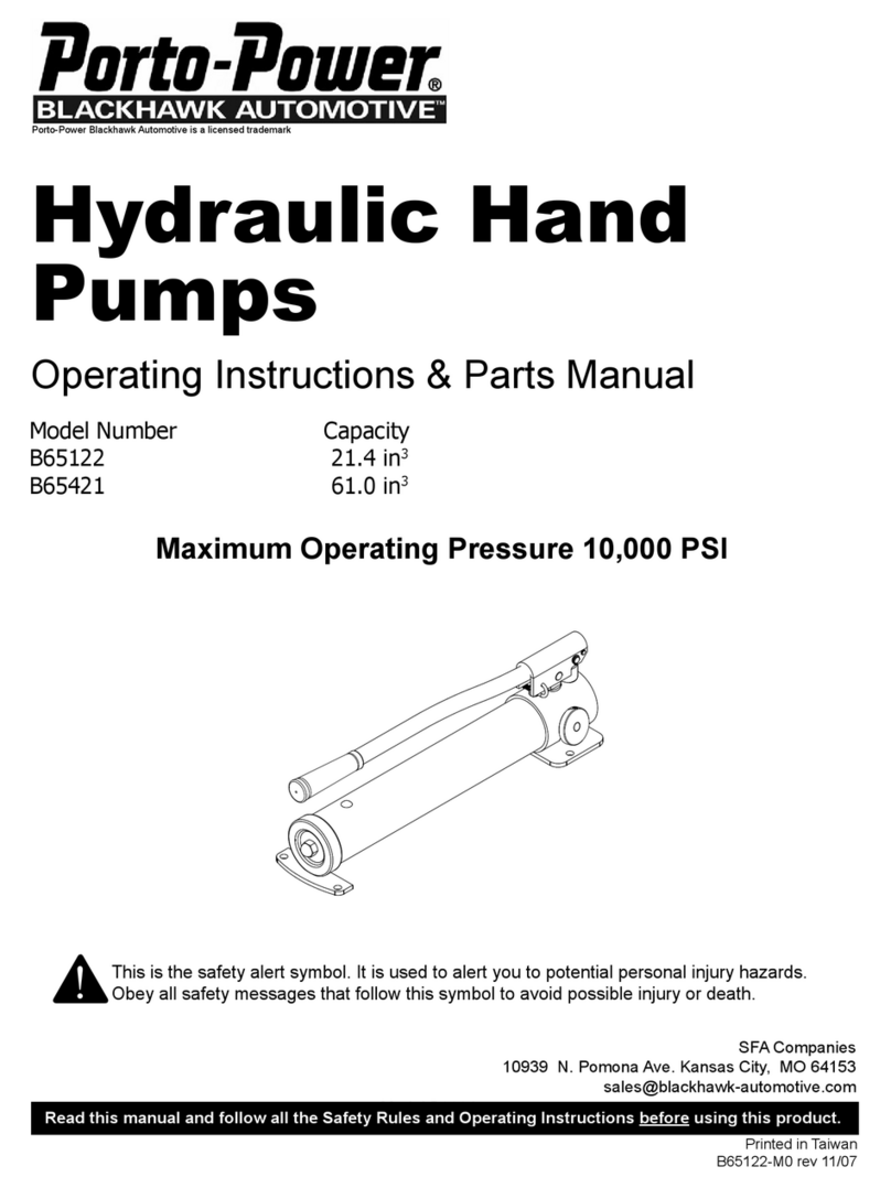
Porto-Power Blackhawk Automotive B93601A Instructions for use

Itemsincluded:
B93600A •10Ton Pulling Post
B65428 • Air Pump with Hose
B65444 • 10 Ton 10" Stroke Ram
B97662 •Chain & Craw Hooks (2pc.)
B97691 •Chain & Grab Hook
Pulling PostKit
Operating Instructions & Parts Manual
- Before using this product, read this manual and follow all its Safety Rules and Operating Instructions
SFA Companies ©2005
10939 N. PomonaAve. Kansas City, MO 64153
816-891-6390
Made in USA
Porto-PowerBlackhawkAutomotiveisalicensedtrademark
Model Number B93601A

2
TIME LIMITED WARRANTY
For the periods of time indicated below, SFA Companies will repair or replace, at its option, without charge, any of its
productswhichfailsduetoadefectinmaterialorworkmanshipundernormalusage.Thislimitedwarrantyisaconsumer's
exclusiveremedy.
Performanceof any obligationunderthis warranty maybe obtained byreturningthe warranted product,freightprepaid,
toSFA Companies Warranty Service Department, 10939 N. PomonaAve.,Kansas City,MO64153.
Except where such limitations and exclusions are specifically prohibited by applicable law.
(1)THE CONSUMER'SSOLEANDEXCLUSIVEREMEDYSHALL BETHEREPAIRORREPLACEMENT OFDEFEC-
TIVEPRODUCTSAS DESCRIBEDABOVE.
(2) SFA COMPANIES SHALL NOT BE LIABLE FORANY CONSEQUENTIAL OR INCIDENTAL DAMAGE OR LOSS
WHATSOEVER.
(3) ANY IMPLIED WARRANTIES, INCLUDING WITHOUT LIMITATION THE IMPLIED WARRANTIES OF
MERCHANTABILITYANDFITNESSFORA PARTICULARPURPOSE,SHALL BELIMITEDTO THE TIMEPERIODS
FORTHEEXPRESSWARRANTYDESCRIBEDABOVE,OTHERWISE THE REPAIR,REPLACEMENTORREFUND
ASPROVIDEDUNDER THISEXPRESS LIMITEDWARRANTY ISTHE EXCLUSIVEREMEDY OFTHE CONSUMER,
ANDIS PROVIDED IN LIEU OFALLOTHERWARRANTIES,EXPRESS OR IMPLIED.
(4)ANY MODIFICATION,ALTERATION,ABUSE, UNAUTHORIZED SERVICE OR ORNAMENTAL DESIGN VOIDS
THISWARRANTYANDISNOTCCOVEREDBYTHISWARRANTY.
Some states do not allow limitations on how long an implied warranty lasts, so the above limitation may not apply to
you. Some states do not allow the exclusion or limitation of incidental or consequential damages, so the above
limitationorexclusionmaynotapplytoyou. Thiswarrantygivesyouspecificlegalrights,andyoumayalsohaveother
rights which vary from state to state.
Items Covered Length of Coverage
B93600A (Pulling Post Frame) Five (5) years from date of first consumer
purchase of the product
B65428 (Air Pump), B65444 (Ram),
B97662 (Chain) & B97691 (Chain) One (1) year from date of first consumer
purchase of the product
SFA Companies ©2005
10939 N. Pomona Ave. Kansas City, MO 64153
816-891-6390

3
SAVE THESE INSTRUCTIONS
Foryoursafety,readandunderstandtheinformationcontainedwithin.Theownerandoperatorshallhavean understanding
ofthis productandsafe operatingproceduresbefore attemptingtouse this product.Instructions and Safetyinformation
shall be conveyed in the operators native language before use of this product is authorized. Make certain that the
operatorthoroughly understands the inherent dangers associated with the use and misuse of the product.Ifanydoubt
exists as to the safe and proper use of this product as outlined in this factory authorized manual, remove from service
immediately.
Inspectbefore each use. Do notuseif broken,bent, crackedorotherwise damagedparts arenoted.If anycomponent
of this product has been or suspected to have been subjected to a load dropped suddenly, unexpectedly upon it,
discontinue use until checked out by a Porto-Power BlackhawkAutomotive Authorized Service Center. Owners and
operators of this equipment shall be aware that the use and subsequent repair of this equipment may require special
training and knowledge. It is recommended that an annual inspection be done by qualified personnel and that any
missing or damaged parts, decals, warning / safety labels or signs be replaced with factory authorized replacement
partsonly. Any component ofthisproduct that appearstobe damaged inanyway, is worn or operates abnormally shall
beremoved fromservice immediately untilsuch timeasit canberepaired/replaced. LabelsandOperator's Manualsare
availablefrommanufacturer.
PRODUCT DESCRIPTION
Porto-Power PullingPost Kit is designed for rated capacity lifting and pulling jobs. This kitincludesapullingpostframe
(B93600A), a 10,000 psi air pump with hose (B65428), a 10 ton 10 inch stroke threaded ram (B65444), a 9 feet chain
with grab hook (B97691), and two 6 feet chain with two craw hooks (B97662). This pulling post can be used with
common pot patterns or new chainless anchor system. Building Block design lets users create their own custum pull
system.A wide variety of applications exist for this category of product. Special skill, knowledge and training may be
requiredfor a specifictaskandthe product maynotbe suitable for allthejobs described above. Unsuitableapplications
wouldinclude applicationsthatcall foradevice tomove,level orsupportpersons, animals,hazardousmaterials, mobile
homes/dwellingsingeneral,mirrorsand/orplateglass,and/ortoconnect/securehatches,components, etc. between
bulkheads. The user must ultimately make the decision regarding suitability of the product for any given task and
assume the responsibility of safety for himself and others in the work area.
SPECIFICATIONS
Height
Base Size
( L x W)
Floating
Pulley
Position
Usable
Oil
Capacity
Rated
Pressure Input Air
pressure Stroke Oil
Capacity Min.
Height
Operating
Pressure
B93601A 10 ton 59" 31" x 16" 10 36.6 in310,000 psi 90-175 psi 10" 22.7 in315 5/8" 8950 psi
Ram
Model Capacity
Pulling Post Frame Air Pump

Porto-Power
BLACKHAWK AUTOMOTIVE
4
SAFETY INSTRUCTIONS
BEFORE USE
1. Study, understand, and follow all instructions provided with and on this device before use.
2. Inspect before each use. Do not use if bent, broken, leaking or damaged components are noted.
3. Ensure that product and application are compatible.
4. Ensure that all parts of your kit are included.
5. Connect hose coupler to ram coupler, ensure that there are no fluid leaks.
6. Ram shold be stored in vertical position.
• If oil leakage is detected, discontinue use of the
ram immediately and contact your nearest
Porto-PowerBlackhawkAutomotiveAuthorized
ServiceCenter. The ram could develop excessive
pressure and cause the ram, hose or coupler to
burst which could cause serious injury or death.
• When loading a ram, always insure that coupler,
port,andadapterthreadshave not been damaged.
Failure to do so could cause serious injury or death.
! DANGER !WARNING
!
Figure1 -B93601A Components
Air Hydraulic Pump
6' Chain with 2
Claw Hooks, 3/8"
Floating Pulley
SupportBar
9' Pull Chain with
GrabHook, 3/8"
10TonThreadedRam
PowerLeverArm
Wheel
HydraulicHose
Oil Outlet Port, 3/8"
Air Inlet Port, 1/4"
Idle Pulley Recycling Lock
SafetyChain
Hanger
Secondary
SafetyTie

!
5
•All WARNING statementsmust becarefully observed
tohelp prevent personal injury.
•Do not exceed rated capacity.
• All devise used must be rated for the same
maximumoperating pressure, correctly connected
and compatible with the hydraulic fluid used.An
improperly matched system can cause the system
to fail and possibly cause serious injury.
• Use only on hard, level surfaces capable of
sustaining rated capacity loads.
• For safety, operate equipment at least 6 feet from
either side of post and chains.
•Do not stand behind post, chain and clamps when
underload.
•Do not use the safety chain under floating pulley as
a "pull" chain.
•On severe pulls, use secondary safety ties and/or
tarps and blankets around chains.
• Do not pull chain over sharp corners. Use protective
pads.
• Listen for popping noises indicating weld fractures
andpossible sudden separation.
• Avoid sudden jerks when applying tension to chain.
•Wear protective clothing and safety goggles to
reduce the risk of injection.
•Do not wear sandals and jewelry when operating
thisequipment.
•Never use chain assemblies not intended for
collision repair equipment.
•The chain/hooks must be 3/8" trade size, heat
treated, alloy type rated for "collision repair"
applications.
• Do not cut chain with cutting torches. Heat will
degradechain.
• Removedamaged,kinked,twisted,stretchedorrusty
chainfromserviceso itcannot beaccidentallyreused.
• Monitor pressure and load at all times.
• Always verify load with calibrated load cell and
indicator,knowngoodpressuregaugeorequivalent
devices.
•As the load is lifted, use blocking and cribbing to
guardagainst a falling load.
•Neverallow personnel to work on, under or around a
loadbeforeitisproperly supported by appropriate
mechanicalmeans.Never rely on hydraulic pressure
alone to support load.
•Allpersonnelmust be clear before lowering.
• Never try to disassemble a ram or pump. Refer
repairsto qualified, authorized personnel.
•Do not modify this device.
•When the ram is not is use, keep ram fully retracted.
•Failure to heed these markings may result in
personalinjuryand/orpropertydamage.
Hydraulic Hoses and Fluid Transmission Lines
• Neveroperate pump with release valve closed and
disconnectedfromapplication. If operated in this
condition, the hose and connections become
pressurized.Thisincreasesbursthazard.Damage
may occur to pump and its components
• Avoid short runs of straight line tubing. Straight line
runsdo not provide for expansion and contraction
dueto pressure and/or temperature changes.
• Reduce stress in tube lines. Long tubing runs
should be supported by brackets or clips. Before
operating the pump, all hose connections must be
tightened with the proper tools. Do not overtighten.
Connections should only be tightened securely and
leak-free.Overtighteningcancausepremature
thread failure or high pressure fittings to burst.
• Should a hydraulic hose ever rupture, burst or need
to be disconnected, immediately shut off the pump
and release all pressure. Never attempt to grasp a
leaking pressurized hose with your hands. The
force of escaping hydraulic fluid can inflict injury.
•Do not subject the hose to potential hazard such
as fire, sharp objects, extreme heat or cold, or
heavyimpact.
•Do not allow the hose to kink, twist, curl, crush, cut
or bend so tightly that the fluid flow within the hose
is blocked or reduced. Periodically inspect the hose
for wear, because any of these conditions can
damage the hose and possibly result in personal
injury.
•Do not pull, position or move setup by the hose.
Doing so can damage the hose and possibly cause
personalinjury.
•Hose material and coupler seals must be compat-
ible with hydraulic fluid used. Hoses also must not
come in contact with corrosive materials such as
batteryacid,creosote-impregnatedobjectsandwet
paint.Hosedeteriorationduetocorrosivematerial
can result in personal injury. Never paint a coupler
orhose.
•Useonly approvedaccessories andapproved
hydraulicfluid.
•To help prevent material fatigue if the ram is to
be used in a continuous application, the load
should not exceed 85% of the rated capacity.
•Usean approved, high-grade pipe thread sealant to
seal all hydraulic connections. Teflon tape can be
used if only one layer of tape is used and it is
applied carefully (two threads back) to prevent the
tape from being introduced into hydraulic system.A
piece of tape could travel through the system and
obstructthe flow of fluid and adversely affect
function.
!WARNING !WARNING

SET UP (refer to figure 1 on page 4)
Safety Mesage! It is recommended that you install a pressure gauge on your pump to indicate a relative level of
pullingforce.
1. Secure the threaded ram to bottom of puller post, then connect ram to air pump with hydraulic hose provided.
2. Slide the 9 feet pull chain thru the floating pully, idle pulley and power lever arm.
3. Secure the safety chain on floating pulley to an anchor pot or between two anchor pots using 6 feet claw hooks
chain
Note: The dual chain helps to devide the pull force exerted by the post and also allows positioning the post between
twoanchor ports.
OPERATION
Note: The pull post is operated by a 10Ton 10 inch stroke hydraulic ram attains 20,000 pounds of pull on the chain
at 8950 psi pressure.
Safety Message! operate equipment from at least 6 feet from either side of post and chains.
1. Adjust the floating pulley to desire height to pull using the handle bar. For low pull, can pull without floating pulley,
just slide thru the idle pully.
2. Connect air nipple (not included) to air input port before connecting air hose.
3. Connect to suitable air supply, ensure air input pressure range from 95 to 175 psi.
4. Secure the pull chain before pulling object.
5. To operate, press the foot pedal of air pump until desire height or position is reached.Always monitor pressure
and load. Do not exceed 8950 psi and use caution when nearing this maximum operating ram pressure.
Caution! Never operate pump with release valve closed and disconnected from ram. If operated in this condition, the
hoseandconnectionsbecomepressurized.Thisincreasesbursthazard.Damagemayoccurtopumpand itscomponents
6. To release, simply press the release valve by stepping on the raised, stirrup shaped portion of the foot pedel.
7. Figure 2 below shows illustrations of common applications.
6
Figure2- Illustrations of different methods for pulling application

7
MAINTENANCE
1. Inpect and replace damaged, kinked, twisted, stretched or rusty chain.
2. Inspect hoses and connections. Replace damage components immediately with Porto-Power Blackhawk
replacement parts only.
3.Tighten connections as needed. Usenon-hardeningpipe thread compound when servicingconnections.
4.Useonlygood quality hydraulic fluid. We recommend Hein-Werner HW93291 or equivalent.
Lubrication
Use a light machine oil to lubricate pivot points, hinges and all joints of post that move under heavy load.
Adding Hydraulic Fluid
1. Depressurize and disconnect hydraulic hose from application.
2. Withpumpinitsvertical position, remove the reservoir cap located on the reservoir.
3. Use a small funnel to fill reservoir to within 3/4" (19mm) of the opening.
Note: Use only a good quality hydraulic jack fluid. Never use brake fluid, transmission fluid, turbine oil, motor oil,
alcohol,glycerin etc. Use of other than good quality hydraulic oil will void warrantyanddamagethepump,hose,
andapplication.
4. Wipe up any spilled fluid. Reinstall the reservoir cap.
Changing Hydraulic Fluid
For best performance and longest life, replace the complete fluid supply at least once per year.
1. Depressurize and disconnect hydraulic hose from application.
2. Repeat #2 above, then pour used fluid into a sealable container.
4. Use a small funnel to fill reservoir to within 3/4" (19mm) of the opening.
5. Dispose of fluid in accordance with local regulations.
6. Fill with a good quality hydraulic oil as recommended above. Reinstall reservoir cap.
Storage
1. Depressurize and disconnect hydraulic hoses from ram.
2. Wipeclean and store in dry environment. Avoidextream temperatures.
TROUBLESHOOTING
Symptom PossibleCauses Corrective Action
Ram will not extend
System does not maintain
pressure
Will not lift to full extension
•Overloadcondition
•Fluidlevel low
•Fluidlevel low
•Air trapped in system
•Hydraulicunit malfunction
•Remedyoverload condition
•Replaceram and / or pump
•Ensureproper fluidlevel
•Withramfullyretracted,removeoil
filler screw to let pressurized air
escape, then reinstall oil filler screw
Poor performance
Ram does not return fluid to
pump (i.e. ram will not retract) •Reservoiroverfilled
•Ramdamaged
•Malfunctioningcoupler,
damagedapplication
•Drainfluid toproperlevel
•Replaceram
•Secure load by other means.
Depressurizepump and hose,
removecoupler and/orapplication,
then replace with a new one.

8
Figure3 - Replacement Parts Illustration for B93601A
REPLACEMENT PARTS
Please refer to the Parts drawing when ordering parts. Not all components are replacement items, but are illustrated
as a convenient reference of location and position in the assembly sequence. Whenordering parts, give model no.,
serial no. and description below. Call or write for current pricing: SFA Companies 10939 N. PomonaAve. Kansas
City,MO 64153, U.S.A. Tel:(816)891-6390 Fax:(816)891-6599 E-Mail: [email protected]
1
11
3
4
5
7
7
2
14
10
9
8
7
15
16
18
17
13
19 20
8
6
12
Item# Part# Description Qty
1600-001-100 Recyling Lock 1
2600-001-201 Heel Block 1
3600-001-203 Floating Pulley with Chain Retarder 1
4600-001-205 Chain Retarder 1
5600-001-206 Idle Pulley 1
6600-001-213 Bar with Clips, D3/4"x3-3/8" 1
7600-001-208 Bar with Clips, D3/4"x7" 3
8600-001-209 Bar with Handle Grip, D3/4"x11" 2
9600-001-210 Wheel Assembly 2
10 600-001-214 Power Lever Arm (for 10" ram) 1
11 600-001-212A Ram Coupling 1
12 B93652A Power Lever Arm Assembly -
13 B93600A Puller Post Frame 1
14 B65444 Ram, 10 Ton 10" Stroke 1
15 B65582 Ram Coupler, 3/8" 1
16 B65581 Hose Coupler, 3/8" 1
17 B65426 Air Pump 1
18 B65594 Hydraulic Hose, 6' x ID3/8" 1
19 B97691 Chain with Grab Hook, 9' x ID3/8" 1
20 B97662 Chain with 2 Claw Hooks, 6' x ID3/8" 2
Table of contents
Other Porto-Power Water Pump manuals
Popular Water Pump manuals by other brands

Titan
Titan 100 owner's manual

Bestway
Bestway 62038 operating instructions

GORMAN-RUPP PUMPS
GORMAN-RUPP PUMPS VG Series Installation, operation, and maintenance manual with parts list

Dantherm
Dantherm CDT 30 installation guide

Lutz-Jesco
Lutz-Jesco MEMDOS SMART LB operating instructions

BUSCH
BUSCH COBRA BC 0101 G instruction manual

Finish Thompson
Finish Thompson HVDP Series Operation-Installation-Parts Manual

Enerpac
Enerpac SCH121H instruction sheet

BUSCH
BUSCH PUMA WP 0250 D4 instruction manual

EINHELL Expert
EINHELL Expert GE-AW 9041 E Original operating instructions

EINHELL
EINHELL RHW 1300 Niro operating instructions

Base
Base RB750 installation instructions