Potter PAD100-SPKB User manual

PAD100-SPKB
Speaker Base
8830143 - REV B • 4/18 PAGE 1 OF 3
Potter Electric Signal Company, LLC • St. Louis, MO • Phone: 800-325-3936 • www.pottersignal.com
Description
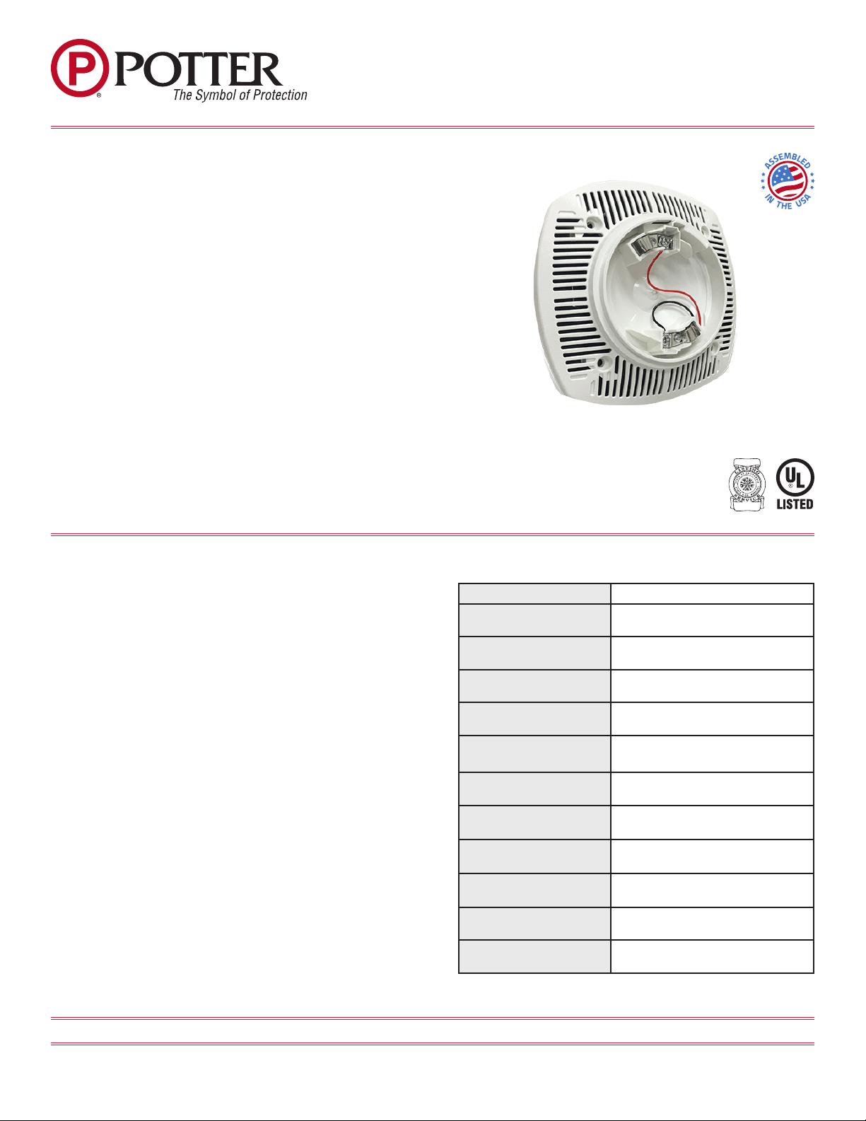
The Speaker Base (PAD100-SPKB) is a wall or ceiling mount
adjustable speaker that may be utilized in a variety of applications.
The speaker is designed to meet code requirements for audio and voice
communications. The PAD100-SPKB offers dependable evacuation
signaling. The PAD100-SPKB provides a 25 or 70.7 VRMs speaker
with eld selectable power taps of 1/8W, 1/4W, 1/2W, 1W, 2W or 4W.
The frequency range of the PAD100-SKPB is 400-4000 Hz and is
suitable for 520 Hz low frequency tone applications. The base has a
locking feature for the sensor that may be used or removed in the eld.
The panel will support any combination of sensors or modules on the
SLC. The PAD100-SPKB does not consume an address on the loop.
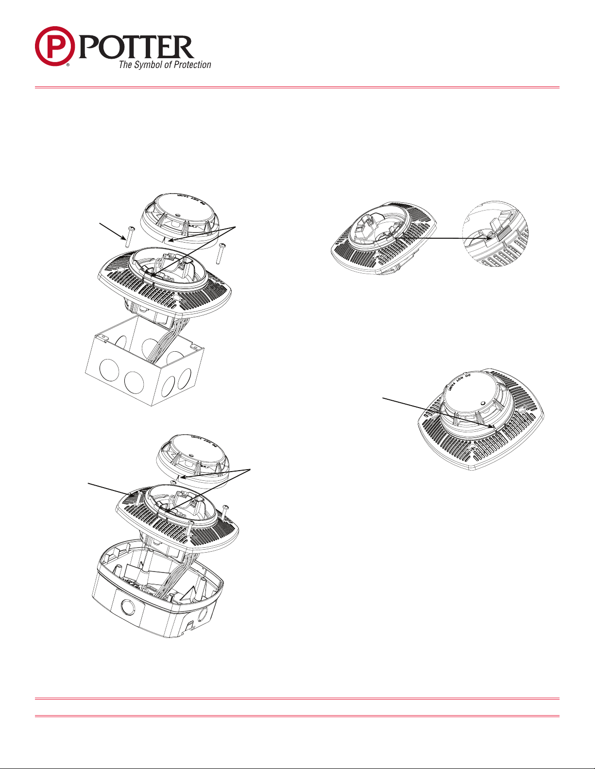
The PAD100-SKPB can be mounted to a 4” by 2-1/8” deep square box
or the LFSBBB-W back box.
The Speaker Base is not an addressable device. Independent control of
the speaker base requires a PAD100-SM speaker module.
Technical Specications
Working Range for SLC 24 VDC
Standby/Alarm Current 150 μA
Installation temperature
range 32°F to 150°F (0°C to 66°C)
Active Current (including
indicator) 3.8 mA
Working Voltage 25 Volts, 70.7 Volts
Power Tap Selection for
SPK
1/8 Watt , 1/4 Watt, 1/2 Watt, 1 Watt,
2 Watt, 4 Watt
Applicable SLC Wiring
Style Class A, Class B, Class X
Active Indicator 1 LED
Operating relative
humidity range 0% to 93% (Non-condensing)
Maximum number of
devices per SLC Loop 127
Dimensions (without
detector)
Height: 2.75 in (70mm)
Diameter: 6 in x 6 in
Mounting Options Wall or Ceiling
Features
• Speaker voltage 25 or 70.7 VRMs standard, eld selectable
• Field selectable power taps: 1/8W, 1/4W, 1/2W, 1W, 2W, 4W
• High quality DBA output (intelligible)
• Frequency range 400-4000 Hz
• Suitable for 520 Hz low frequency signaling applications
• Screw terminals, separate in/out wiring (18-12 gauge)
• SLC supports NFPA Class B, A and X wiring
• Tamperproof grill
• Off White Faceplate
• Product includes a 5 year warranty

8830143 - REV B • 4/18 PAGE 2 OF 3
Potter Electric Signal Company, LLC • St. Louis, MO • Phone: 800-325-3936 • www.pottersignal.com
PAD100-SPKB
Speaker Base
Detector Base Mounting Locking Feature
PAD100-SPKB should be mounted directly on an electrical box (see
Figure 1) or the LFSBBB-W back box (see Figure 2). The PAD100-
SPKB mounting holes are congured for a 4” x 2-1/8” deep square
box. Use a box for each base and run the power circuit to all base
locations.
Eliminate the Locking Feature
PAD100-SPKB include a locking feature that prevents removal of the
detector and removal of the base cover without using a tool.
1. To eliminate this feature, break off the locking tab and then install
the detector. See Fig. 3.
Removing of Detector Head from Base
2. To remove the detector from the base once the locking feature has
been activated, insert a small screwdriver into the slot on the base to
push the plastic tab while simultaneously turning the detector head
counter-clockwise. See Fig. 4.
3. To remove the base cover from the lower enclosure once the locking
feature has been activated, insert a small screwdriver into the slot on
the on the base to push the plastic tab while simultaneously turning the
detector head counter-clockwise.
Four screws are
provided, two for
securing speaker to
the back box and two
for aesthetics. The two
non-functional screws
will be held in place
by the pressure t of
the faceplate.
Mount the detector
bracket to the back box
using the mounting
screws.
Break off tab (gray
area) in image to disable
locking feature.
Insert small screwdriver
into slot to remove
detector from base.
Alignment
Features
Fig. 1
Fig. 3
Fig. 4
Alignment
Features
Mount the detector
bracket to the back box
using the mounting
screws.
Fig. 2
Four screws are
provided, two for
securing speaker to
the back box and two
for aesthetics. The two
non-functional screws
will be held in place
by the pressure t of
the faceplate.

8830143 - REV B • 4/18 PAGE 3 OF 3
Potter Electric Signal Company, LLC • St. Louis, MO • Phone: 800-325-3936 • www.pottersignal.com
PAD100-SPKB
Speaker Base
Model Description Stock No.
PAD100-SPKB Speaker Base 3992762
LFSBB-W Speaker Base Back Box 3992761
Ordering Information
Wiring Diagrams
The SLC supports NFPA wiring Class B, A and X. In the Class A
arrangement, two separate conductors would return from the last
detector base to a listed compatible Fire Alarm Control Panel (FACP).
The frequency range of the PAD100-SPKB is 400-4000Hz and is
suitable for line supervision.
Fig. 5
SPK SLC
Adjust power taps using needle
nose pliers.
PAD100-SPKB Field Selectable Power Tap Selection - Reverberant (dBA @ 10ft.)
Voltage 1/8 Watt 1/4 Watt 1/2 Watt 1 Watt 2 Watt 4 Watt
25 Volts 75.0 dBA 78.1 dBA 81.2 dBA 83.8 dBA 86.6 dBA 89.7 dBA
70.7 Volts 75.1 dBA 78.1 dBA 80.9 dBA 83.8 dBA 86.9 dBA 89.6 dBA
System Considerations
1. To select the proper wattage input for the speaker, move the jumper
to the appropriate pin.
2. Always maintain electrical isolation between speaker and strobe
wiring on combination units.
3. Do not exceed 130% of rated speaker voltage. If excessive distortion
is heard, check amplier for signal clipping. If clipping exists, reduce
either amplier input or gain.
Other Potter Speakers manuals