manuals.online logo
Brands
  1. Home
  2. •
  3. Brands
  4. •
  5. Meyer Sound
  6. •
  7. Speakers
  8. •
  9. Meyer Sound MSL-5 User manual

Meyer Sound MSL-5 User manual

Operating Instructions
Meyer Sound Laboratories, Inc.
2832 San Pablo Avenue
Berkeley, CA 94702
MSL-5
Loudspeaker
loudspeaker constructed as a 30-degree arrayable
section, and is designed to be operated with the
Meyer Sound M-5 Control Electronics Unit (one M-
5 per channel). The M-5 comprises electronic
crossover, Meyer Sound's exclusive
SpeakerSense™ driver protection circuitry, and
amplitude and phase response alignment circuitry
optimized for the loudspeaker.
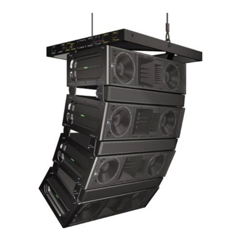
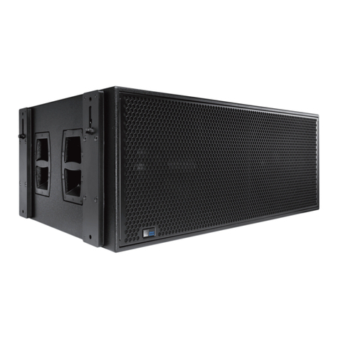
The Meyer Sound MSL-5 is an extremely high-
power, high-performance loudspeaker designed for
large-scale music reinforcement and public address
applications. It is a bi-amplified system consisting
of two proprietary 12" cone drivers in a unique
horn-loaded vented enclosure, and three 2" throat
diameter (4" diaphragm) high frequency drivers with
vertical 70-degree horns. The MSL-5 is a full-range
Operating Instructions
Meyer Sound Laboratories, Inc.
2832 San Pablo Avenue
Berkeley, CA 94702
MSL-5
Loudspeaker
Amplifier
Requirements The MSL-5 requires two channels of amplification with
each channel meeting the following specifications:
1. Inputs. Must utilize XLR-type connectors with bal-
anced input circuitry wired such that a positive voltage on
connector pin 3 results in a positive voltage at the ampli-
fier output.
2. Voltage Gain. Must be fixed at 16 dB (6.3 volts out
for 1 volt in) when measured from input to output.
3. Mains AC Power. AC power inlet must be a three-
circuit grounded plug with earth (mains AC) ground
permanently connected to chassis. The amplifier must
meet the power output criteria over a line voltage range
of 180V to 260V AC, 50/60 Hz (may be split into two
switch-selectable ranges).
4. Power Output. Each channel of amplification must
meet two power criteria:
• The amplifier must be capable of driving an 8Ωload
at 367 W continuously for 60 minutes without shut-
down or distortion exceeding 0.1%. Following the
above preconditioning, it must deliver 1100 W for 5
minutes without shut-down or distortion exceeding
0.1%.
• The amplifier must be capable of driving a 4Ωload
at 1800 W in 0.5 sec. bursts without shut-down,
peak clamping or distortion exceeding 0.1%.
It is highly recommended that only one high or low
frequency section of the MSL-5 be driven by a single
amplifier channel as each section represents a 4 ohm
load.
For further information on power amplifiers, please refer
to Power Amplifier Criteria, a Meyer Sound Technical
Note available from your dealer.
The MSL-5 is a bi-amplified system and must be used
with the M-5 Control Electronics Unit. The M-5 func-
tions as an active crossover, dividing the input signal into
high and low frequency components. The connection
terminals of the high and low frequency drivers appear
on a single EP-type 4-pin connector located on the rear
of the MSL-5 cabinet. The pin assignments for this
connector are:
Pin 1–Low frequency drivers, hot
Pin 2–Low frequency drivers, common
Pin 3–High frequency drivers, common
Pin 4–High frequency drivers, hot
(When the cabinet is fitted with an EP-5 connector for
European use, Pin 5 is unconnected.)
Note: If you are using standard Meyer Sound loud-
speaker cables and adapters, simply connect the fe-
male end of the speaker cable to the MSL-5, the male
end of the cable to the Meyer Sound pigtail adapter,
and the banana connectors of the adapter to your
amplifier outputs. In making connections between the
MSL-5 and its amplifiers, be sure to connect the 12-inch
drivers to the Lo amplifier, and the horn drivers to the
Hi amplifier. The adapter banana plugs are color-
coded as follows:
Red – Low frequency drivers
Black – High frequency drivers
For connections between the M-5 and the power ampli-
fiers, refer to the M-5 Operating Instructions.
The minimum wire size for connections between the
MSL-5 and the power amplifiers is 14 gauge (larger for
runs over 100 feet).
Connections
Verifying System
Polarity All Meyer Sound loudspeakers are thoroughly tested in
all stages of manufacture and correct polarity of indi-
vidual cabinets is assured. However, accidental polarity
reversal is possible when there are multiple amplifier
connections, and a single cabinet which is out of polarity
with the rest of its array will cause severe cancellation.
This will result in a noticeable decrease in SPL and
possible component damage.
Because of the extensive signal processing circuitry of
the M-5 Control Electronics Unit, the "phase-popper"
type of speaker polarity checkers cannot reliably be used
to test for correct polarity of the low and high drivers of
the MSL-5. However, because the MSL-5 is phase-
corrected through crossover, many of the portable spec-
trum analyzers can be used, with a pink noise source, to
test for driver polarity as follows:
1. Single cabinets. First, verify polarity of the woofers
by connecting a 9 volt battery at the end of the loud-
speaker cable.
EP connector Battery
Pin 1 + terminal
Pin 2 – terminal
• The woofer cones should move outward. Connect
the speaker cable to the amplifier.
• Input the pink noise source to the M-5 and advance
its level control to a convenient measuring level.
• Standing in front of the loudspeaker, position the
analyzer microphone directly between the HF horns
section and the 12-inch drivers, at a right angle to
Operating Instructions
Meyer Sound Laboratories, Inc.
2832 San Pablo Avenue
Berkeley, CA 94702
MSL-5
Loudspeaker
the cabinet face, and about 1 meter in front of the
MSL-5.
• If polarity of the high frequency drivers is reversed, a
trough will appear in the response curve centered
near 800 Hz. If in doubt, reverse the polarity of the
Hi amplifier output while you watch the analyzer
display.
2. Multiple cabinet arrays. Each cabinet should first be
tested as above.
• Connect one loudspeaker and advance the pink
noise to a convienent measuring level. Position the
measuring microphone on the axis between the
loudspeaker and the cabinet adjacent to it, and
about 2 meters distant. Note the frequency re-
sponse and overall level.
• Leaving the first loudspeaker connected, connect
the adjacent one and observe the analyzer display.
The entire curve should jump up in level, indicating
correct addition between the loudspeakers. A polar-
ity reversal between the loudspeakers will show up
as severe broadband cancellation.
• Similarly, add in the rest of the cabinets of the array
one at a time, looking for correct addition as each
loudspeaker is connected. (It will be necessary to
reposition the microphone.)
Rigging The MSL-5 loudspeaker has twelve offset pivoting lift
rings (6 top and 6 bottom) fastened externally through
cabinet cut-outs to an internal steel frame. Please
consult Meyer Sound about any questions concerning
MSL-5 rigging strength and loading conditions. If the
structural integrity of any cabinet has been compromised
by damage or negligence, then the safety of the rigging
cannot be assured. All rigging should be done by
competent professionals.
Placement and
Arraying The MSL-5 is designed to function as a 30-degree
arrayable section with additional cabinets being em-
ployed as modular 30-degree building blocks.
42.52
56.75
32.28
22.51
14.00
7.38
32.19
C
SYM
24.18
1.63
3.12
C
30.42
15°
26.88
29.39
REF
Front Side Rear
Top
(TYP, BOTH ENDS)
EP-4 CONN, TYP
EP-5, EUROPE ONLY
PYLE, OPTIONAL
±0.50
28.63 C.G.
14.00 C.G. ±0.50
Operating Instructions
Meyer Sound Laboratories, Inc.
2832 San Pablo Avenue
Berkeley, CA 94702
MSL-5
Loudspeaker
Specifications Acoustical MSL-5 / M-5 System1 (two 30osections)
Frequency Response2100 Hz - 16 kHz ±4 dB
Maximum SPL at 100 feet
Continuous 110 dB
Peak 120 dB
HF Coverage
Horizontal 60 degrees
Vertical 70 degrees
MSL-5 Loudspeaker (one 30osection)
Driver Complement
Low Frequency Drivers (2) MS-12 12-inch cone drivers
High Frequency Drivers (3) MS-2001A 2-inch throat (4" diaphragm)
compression drivers
HF DC Protection 50 µf polypropylene capacitor
Enclosure Vented, horn-loaded multi-ply hardwood
Finish Black textured
Protective Grill Two piece hex perforated metal, powder
coated, charcoal-grey foam covering
Rigging 12 points, offset pivoting lift rings mounted on
internal steel framing
Dimensions 42.52" W x 56.75" H x 32.28" D
Weight 480 lbs. (218.2 kg)
Connector EP-4 (male),
EP-5 (male, Europe only)
Pyle National (optional)
Notes:
1. Acoustical specifications are given for the minimum configuration of two 30-degree sections.
2. Measured 5 meters on axis, free-field conditions, pink noise input, in third-octave bands.
05.022.017.01 A
© 1994, Meyer Sound

Other Meyer Sound Speakers manuals

Meyer Sound Self-Powered Reinforcement Loudspeaker MTS-4 User manual

Meyer Sound

Meyer Sound Self-Powered Reinforcement Loudspeaker MTS-4 User manual

Meyer Sound Self-Powered Reinforcement Loudspeaker MTS-4 User manual

Meyer Sound

Meyer Sound Self-Powered Reinforcement Loudspeaker MTS-4 User manual

Meyer Sound High-Power Loudspeaker MSL-2A User manual

Meyer Sound

Meyer Sound High-Power Loudspeaker MSL-2A User manual

Meyer Sound MILO 120 User manual

Meyer Sound

Meyer Sound MILO 120 User manual

Meyer Sound CQ-1 User manual

Meyer Sound

Meyer Sound CQ-1 User manual

Meyer Sound UltraCompact High-Power Curvilinear Array Loudspeaker... User manual

Meyer Sound

Meyer Sound UltraCompact High-Power Curvilinear Array Loudspeaker... User manual

Meyer Sound UltraMonitor UM-1C User manual

Meyer Sound

Meyer Sound UltraMonitor UM-1C User manual

Meyer Sound UP-4XP User manual

Meyer Sound

Meyer Sound UP-4XP User manual

Meyer Sound MSL-10A User manual

Meyer Sound

Meyer Sound MSL-10A User manual

Meyer Sound Ashby-5C User manual

Meyer Sound

Meyer Sound Ashby-5C User manual

Meyer Sound M1D User manual

Meyer Sound

Meyer Sound M1D User manual

Meyer Sound CQTM Series User manual

Meyer Sound

Meyer Sound CQTM Series User manual

Meyer Sound 1100-LFC User manual

Meyer Sound

Meyer Sound 1100-LFC User manual

Meyer Sound Studio Reference Monitor System 833 User manual

Meyer Sound

Meyer Sound Studio Reference Monitor System 833 User manual

Meyer Sound Self-Powered Loudspeaker HM-1 User manual

Meyer Sound

Meyer Sound Self-Powered Loudspeaker HM-1 User manual

Meyer Sound UPL-2 User manual

Meyer Sound

Meyer Sound UPL-2 User manual

Meyer Sound MM-4XP User manual

Meyer Sound

Meyer Sound MM-4XP User manual

Meyer Sound Stella-4 Constellation User manual

Meyer Sound

Meyer Sound Stella-4 Constellation User manual

Meyer Sound Acheron 100 User manual

Meyer Sound

Meyer Sound Acheron 100 User manual

Meyer Sound Self-Powered Studio Monitor HM-1S User manual

Meyer Sound

Meyer Sound Self-Powered Studio Monitor HM-1S User manual

Meyer Sound 750-LFC User manual

Meyer Sound

Meyer Sound 750-LFC User manual

Meyer Sound Stella-8C User manual

Meyer Sound

Meyer Sound Stella-8C User manual

Meyer Sound LEOPARD User manual

Meyer Sound

Meyer Sound LEOPARD User manual

Meyer Sound Stella - 4 Constellation User manual

Meyer Sound

Meyer Sound Stella - 4 Constellation User manual

Popular Speakers manuals by other brands

Anchor AN-1000X+ owner's manual

Anchor

Anchor AN-1000X+ owner's manual

PHL Audio 5100 Specifications

PHL Audio

PHL Audio 5100 Specifications

JAMO A 355 user guide

JAMO

JAMO A 355 user guide

Tannoy REVEAL 66 owner's manual

Tannoy

Tannoy REVEAL 66 owner's manual

Turcom HR903 instruction manual

Turcom

Turcom HR903 instruction manual

Orion COBALT CM65 manual

Orion

Orion COBALT CM65 manual

Memorex MSBW101 quick start guide

Memorex

Memorex MSBW101 quick start guide

Kogan KABTSXXBLKA user manual

Kogan

Kogan KABTSXXBLKA user manual

Ateis PENTON RNS Series installation guide

Ateis

Ateis PENTON RNS Series installation guide

Mi WLSYJ01CM quick start guide

Mi

Mi WLSYJ01CM quick start guide

fontastic Hora user manual

fontastic

fontastic Hora user manual

Motorola Sonic Play+ 275 quick start guide

Motorola

Motorola Sonic Play+ 275 quick start guide

EarthQuake ONE-HANDER OH6 user manual

EarthQuake

EarthQuake ONE-HANDER OH6 user manual

SE m-a2 user manual

SE

SE m-a2 user manual

MK Sound SURROUND-550THX Operation manual

MK Sound

MK Sound SURROUND-550THX Operation manual

EisSound KBSound iSelect user manual

EisSound

EisSound KBSound iSelect user manual

Promate LumiPlay user guide

Promate

Promate LumiPlay user guide

Philips HTL5120 quick start guide

Philips

Philips HTL5120 quick start guide

manuals.online logo
manuals.online logoBrands
  • About & Mission
  • Contact us
  • Privacy Policy
  • Terms and Conditions

Copyright 2025 Manuals.Online. All Rights Reserved.