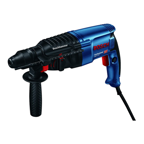
Power works HMM402 User manual

HMM402
PD24SDS1
OPERATOR MANUAL / BEDIENUNGSHANDBUCH / MANUAL DEL OPERARIO /
MANUALE DELL’OPERATORE / MANUEL OPÉRATEUR / MANUAL DE UTILIZAÇÃO /
GEBRUIKSAANWIJZING / РУКОВОДСТВО ОПЕРАТОРА / KÄYTTÖOPAS /
ANVÄNDARHANDBOK / BRUKERVEILEDNING / BRUGSVEJLEDNING / INSTRUKCJA
UŻYTKOWNIKA / NÁVOD K OBSLUZE / NÁVOD NA OBSLUHU / Uporabniški priročnik /
PRIRUČNIK ZA RUKOVANJE / HASZNÁLATI ÚTMUTATÓ / MANUAL DE UTILIZARE /
РЪКОВОДСТВО НА ОПЕРАТОРА / ΕΓΧΕΙΡΙΔΙΟ ΧΡΗΣΗΣ / / KULLANIM
KILAVUZU / / OPERATORIAU VADOVAS / LIETOTĀJA ROKASGRĀMATA /
KASUTUSJUHEND
OriginalInstructions / Übersetzung der Originalanweisungen/ Traducciónde las instrucciones originales/ Traduzione delle istruzioni originali/ Traductiondes
instructions d'origine/ Traduzidoa partir das instruções originais/ Vertaling van de originelegebruiksaanwijzing/ Переводоригинальных инструкций/
Alkuperäisten ohjeiden käännös/ Översättning av originalinstruktionerna/ Produsentens instruksjoner / Oversættelse af de originale vejledninger/ Tłumaczenie
oryginalnej instrukcji / Překlad originálního návodu/ Prekladoriginálneho návodu / Prevodoriginalnih navodil/ Prijevod izvornih uputa/ Az eredeti utasítás
fordítása/ Traducere a instrucţiunilor originale/ Превод на оригиналните инструкции / Αυθεντικέςοδηγίες/ / Orijinal
Talimatların Tercümesi // Originalių instrukcijųvertimas/ Instrukcijutulkojums no oriģinālvalodas/ Originaalkasutusjuhendi tõlge

DECLARATION OF CONFORMITY (UK)
Name and address of the manufacturer:
Name: GLOBGRO AB
Globe Group Europe
Address: Riggaregatan 53, 211 13 Malmö Sweden
Name and address of the Authorized representative:
Name: Garden Equipment Ltd
Address:
Name and address of the person authorised to compile the technical file:
Name: Simon Del-Nevo
Address:
Here with we declare that the product
Category:
Model: HMM402
Serial number: See product rating label
Year of Construction: See product rating label
• is in conformity with the relevant provisions of the Supply of Machinery (Safety) Regulations 2008.
• is in conformity with the provisions of the following other UK legislation:
• Electromagnetic Compatibility Regulations 2016
• The Restriction of the Use of Certain Hazardous Substances in Electrical and Electronic Equipment Regulations 2012
Furthermore, we declare that the following standard have been used:
BS EN 60745-1, BS EN 60745-2-6,BS EN 55014-1, BS EN 55014-2, BS EN 62321-3-1, BS EN 62321-4,
BS EN 62321-5, BS EN 62321-6, BS EN 62321-7-1,BS EN 62321-7-2, BS EN 62321-8
Place, date: Christchurch, Dorset, UK 07.06.2021 Signature: Ted Qu, Quality Director
First Floor, 3a Groveley Road, Christchurch, Dorset, BH23 3HB, UK
SDS Rotary Hammer

1 Description.........................................4
1.1 Purpose.............................................................. 4
1.2 Overview........................................................... 4
2 General safety warnings................... 4
3 Installation......................................... 4
3.1 Unpack the machine.......................................... 4
3.2 Install the battery pack.......................................4
3.3 Remove the battery pack................................... 4
3.4 Install the bit...................................................... 4
3.5 Remove the bit...................................................4
3.6 Fit and change the SDS bit................................ 4
4 Operation........................................... 5
4.1 Start the machine............................................... 5
4.2 Stop the machine............................................... 5
4.3 Adjust the direction button................................ 5
4.4 Select the mode..................................................5
4.5 Drill materials....................................................5
5 Maintenance.......................................5
5.1 General manintenance....................................... 6
6 Technical data....................................6
7 Warranty............................................6
8 EC Declaration of conformity..........6
3
English EN

1 DESCRIPTION
1.1 PURPOSE
The machine is intended for hammer drilling in concrete,
bricks and masonry, as well as for light chiselling work. It is
also suitable for drilling without impact in wood, metal,
ceramics and plastic, as well as for screwdriving.
1.2 OVERVIEW
Figure 1.
1Clamp collar
2Mode selection switch
3Direction button
4Switch trigger
5LED work light
2 GENERAL SAFETY
WARNINGS
WARNING
Read all safety warnings, instructions, illustrations and
specifications provided with this machine. Failure to
follow all instructions listed below may result in electric
shock, fire and/or serious injury.
Save all warnings and instructions for future reference.
The term "power tool" in the warnings refers to your mains-
operated (corded) power tool or battery-operated (cordless)
power tool.
3 INSTALLATION
3.1 UNPACK THE MACHINE
WARNING
Make sure that you correctly assemble the machine before
use.
WARNING
• If parts of the machine are damaged, do not use the
machine.
• If you do not have all the parts, do not operate the
machine.
• If parts are damaged or missing, contact the service
center.
1. Open the package.
2. Read the documentation provided in the box.
3. Remove all the unassembled parts from the box.
4. Remove the machine from the box.
5. Discard the box and packing material in compliance with
local regulations.
WARNING
For your personal safety, do not insert battery before the
tool is assembled completely.
3.2 INSTALL THE BATTERY PACK
Figure 2.
WARNING
• If the battery pack or charger is damaged, replace the
battery pack or the charger.
• Stop the machine and wait until the motor stops before
you install or remove the battery pack.
• Read, know, and follow the instructions in the battery
and charger manual.
1. Align the lift ribs on the battery pack with the grooves in
the battery compartment.
2. Push the battery pack into the battery compartment until
the battery pack locks into place.
3. When you hear a click, the battery pack is installed.
3.3 REMOVE THE BATTERY PACK
Figure 2.
1. Push and hold the battery release button.
2. Remove the battery pack from the machine.
3.4 INSTALL THE BIT
Figure 3.
1. Put the direction button in the center position to lock the
switch trigger.
2. Put bit straight into clamp collar.
3.5 REMOVE THE BIT
Figure 4.
1. Pull back the clamp collar and remove the bit.
3.6 FIT AND CHANGE THE SDS BIT
This machine is equipped with an SDS Plus connection
system.
1. Clean the bit and grease it with machine grease before
inserting it into the chuck.
2. Pull back the clamp collar and hold it.
3. Push and turn the dust-free tool into the bit holder as far
as it can go.
4. Release the clamp collar to lock the bit.
5. Examine that bit has locked by pulling on it.
4
English
EN

4 OPERATION
WARNING
Always wear eye protection.
WARNING
Do not use any attachments or accessories not
recommended by the manufacturer of this product.
4.1 START THE MACHINE
Figure 6.
1. Push the switch trigger.
4.2 STOP THE MACHINE
Figure 6.
1. Release the switch trigger.
4.3 ADJUST THE DIRECTION
BUTTON
Figure 7.
The machine has the direction button (forward/reverse lock)
above the switch trigger to chang the direction of the bit.
1. When the direction button is on the left side of the switch
trigger, the bit direciton is forward.
2. When the direction button is on the right side of the
switch trigger, the bit direction is reversible.
3. Put the direction button in the OFF (center lock) position
to help decrease the possibility of accidental start when
not operate.
CAUTION
To prevent gear damage, always let the chuck come to a
complete stop.
NOTE
The machine does not operate until the direction button is
pushed fully to the left or right.
4.4 SELECT THE MODE
Figure 5.
To change the operation mode, push the release button and
turn the mode selection switch to the correct position until it
clicks.
The machine is used for two functions: drill, hammer drill.
NOTE
Hammer drilling mode can destroy the structure of the
machine when used for fastening or drilling without SDS
Plus bits.
Use bits only with hard metal and SDS Plus shaft only.
NOTE
When hammer drilling, do not apply too much pressure.
4.5 DRILL MATERIALS
WOOD DRILLING
For maximum performance, use high speed steel bits for
wood drilling.
1. Operate the machine at a very low speed to prevent the
bit from slipping off the starting point. Increase the speed
as the drill bit bites into the material.
2. When drilling through holes, put a piece of wood behind
the workpiece to prevent ragged or splintered edges on
the rear side of the hole.
METAL DRILLING
For maximum performance, use high speed steel bits for
metal or steel drilling.
1. Operate the machine at a very low speed to prevent the
bit from slipping off the starting point.
2. Hold a speed and pressure which let cut without
overheating the bit. Apply too much pressure can:
Overheat the drill; Wear the bearings; Bend or burn bits;
and Produce off-center or irregular-shaped holes.
3. When drilling large holes in metal, start with a small bit,
then complete with a large bit. Also, lubricate the bit with
oil to improve drilling action and increase bit life.
MASONRY DRLLING
For maximum performance, use carbide-tipped masonry
impact bits when drilling holes in brick, tile, concrete, etc..
1. Move adjustment button on hammer drill left for hammer
mode.
2. Apply light pressure and medium speed for best results in
brick.
3. When drilling holes in tile, practice on a scrap piece to
find the best speed and pressure. Operate the machine at a
very low speed to prevent the bit from slipping off the
starting point.
5 MAINTENANCE
WARNING
Remove the battery pack from the machine before
maintenance.
5
English EN

WARNING
Do not use strong solvents or detergents on the plastic
housing or components.
5.1 GENERAL MANINTENANCE
• Before each use, examine the machine for damaged,
missing, or loose parts such as screws, nuts, bolts and
caps.
• Clean the machine with a dry cloth. Do not use slovents.
WARNING
Do not let brake fluids, gasoline, petroleum-based materials
touch the plastic parts. Chemicals can cause damage to the
plastic, and make the plastic unserviceable.
CAUTION
Use only approved replacement parts.
6 TECHNICAL DATA
Voltage 24 V
No load speed 0~1440 min-1
Impact rate 0~4800 min-1
Single impact force (EPTA) 1.2 J
Concrete drilling diameter 12 mm
Stone drilling diameter 12 mm
Steel drilling diameter 13 mm
Wood drilling diameter 25 mm
Weight without battery 1.24 kg
Battery model P24B2/P2448B2 and other
BAM series
Charger model P2448C and other CAM ser-
ies
Measured sound pressure
level
88.2 dB(A), KpA=3 dB (A)
Measured sound power level 99.2 dB(A), KwA=3 dB (A)
Vibration 15.671m/s2, K=1.5m/s2
The recommended ambient temperature range:
Item Temperature
Appliance storage tempera-
ture range
32°F (0°C) - 113°F (45°C)
Appliance operation temper-
ature range
32°F (0°C) - 113°F (45°C)
Battery charging temperature
range
39°F (4°C) - 104°F (40°C)
Item Temperature
Charger operation tempera-
ture range
39°F (4°C) - 104°F (40°C)
Battery storage temperature
range
32°F (0°C) - 113°F (45°C)
Battery discharging tempera-
ture range
32°F (0°C) - 113°F (45°C)
7 WARRANTY
(The full warranty terms and conditions can be found on
Powerworks website)
The Powerworks warranty is 3 years on the product, and 2
years on batteries (consumer/private usage) from the date of
purchase. This warranty covers manufacturing faults. A faulty
product under warranty might be either repaired or replaced.
A unit that has been misused or used in other ways then
described in the owner’s manual might be rejected for
warranty. Normal wear, and wear parts are not considered as
warranty. The original manufacturer warranty is not affected
by any additional warranty offered by a dealer or retailer.
A faulty product must be returned to the point of purchase in
order to claim for warranty, together with the proof of
purchase (receipt).
8 EC DECLARATION OF
CONFORMITY
Name and address of the manufacturer:
Name: GLOBGRO AB
Globe Group Europe
Address: Riggaregatan 53, 211 13 Malmö, Sweden
Name and address of the person authorised to compile the
technical file:
Name: Micael Johansson
Address: Riggaregatan 53, 211 13 Malmö, Sweden
Herewith we declare that the product
Category: SDS Rotary Hammer
Model: HMM402
Serial number: See product rating label
Year of Construction: See product rating label
• is in conformity with the relevant provisions of the
Machinery Directive 2006/42/EC.
• is in conformity with the provisions of the following
other EC-Directives:
• 2011/65/EU & (EU)2015/863
6
English
EN

• 2014/30/EU
Furthermore, we declare that the following parts, clauses of
European harmonised standards have been used:
• EN 60745-1; EN 60745-2-6; EN 55014-1; EN 55014-2;
IEC 62321-3-1; IEC 62321-4; IEC 62321-5; IEC
62321-6; IEC 62321-7-1; IEC 62321-7-2; IEC 62321-8
Place, date: Malmö, 07.07.2021 Signature: Ted Qu,
Quality Director
7
English EN

1 Beschreibung......................................9
1.1 Verwendungszweck........................................... 9
1.2 Übersicht............................................................9
2 Allgemeine Sicherheitshinweise....... 9
3 Montage..............................................9
3.1 Maschine auspacken..........................................9
3.2 Akkupack einsetzen...........................................9
3.3 Akkupack entfernen...........................................9
3.4 Einsetzen des Bohrers........................................9
3.5 Entfernen des Bohrers....................................... 9
3.6 Einsetzen und Wechseln von SDS-Bohrern...... 9
4 Bedienung.........................................10
4.1 Maschine starten..............................................10
4.2 Maschine anhalten........................................... 10
4.3 Einstellen der Richtungstaste...........................10
4.4 Modus wählen..................................................10
4.5 Bohrmaterialien............................................... 10
5 Wartung und Instandhaltung.........11
5.1 Allgemeine Wartung........................................ 11
6 Technische Daten............................. 11
7 Garantie............................................11
8 EG-Konformitätserklärung............11
8
Deutsch
DE

1 BESCHREIBUNG
1.1 VERWENDUNGSZWECK
Die Maschine ist für das Hammerbohren in Beton, Ziegel und
Mauerwerk sowie für leichte Meißelarbeiten vorgesehen. Sie
eignet sich auch zum stoßfreien Bohren in Holz, Metall,
Keramik und Kunststoff sowie zum Schrauben.
1.2 ÜBERSICHT
Abbildung 1.
1Klemmhals
2Modus-
Auswahlschalter
3Richtungstaste
4Schaltauslöser
5LED-Arbeitsleuchte
2 ALLGEMEINE
SICHERHEITSHINWEISE
WARNUNG
Lesen Sie alle Sicherheitshinweise, Anweisungen,
Abbildungen und Spezifikationen, die mit diesem Gerät
geliefert werden. Die Nichtbeachtung der unten
aufgeführten Anweisungen kann zu Stromschlag, Feuer und/
oder schweren Verletzungen führen.
Bewahren Sie alle Sicherheitshinweise und Anweisungen
zur späteren Verwendung auf.
Der Begriff "Elektrowerkzeug" in den Sicherheitshinweisen
bezieht sich auf Ihr netzbetriebenes (kabelgebundenes)
Elektrowerkzeug oder akkubetriebenes (kabelloses)
Elektrowerkzeug.
3 MONTAGE
3.1 MASCHINE AUSPACKEN
WARNUNG
Vergewissern Sie sich, dass Sie die Maschine vor dem
Gebrauch richtig montiert haben.
WARNUNG
• Bei beschädigten Maschinenteilen dürfen Sie die
Maschine nicht verwenden.
• Wenn Sie nicht alle Teile haben, dürfen Sie die
Maschine nicht in Betrieb nehmen.
• Wenn Teile beschädigt sind oder fehlen, wenden Sie
sich an die Servicestelle.
1. Öffnen Sie die Verpackung.
2. Lesen Sie die beiliegende Dokumentation.
3. Entnehmen Sie alle unmontierten Teile aus dem Karton.
4. Nehmen Sie die Maschine aus dem Karton.
5. Entsorgen Sie den Karton und das Verpackungsmaterial
gemäß den örtlichen Vorschriften.
WARNUNG
Zu Ihrer eigenen Sicherheit dürfen Sie den Akkupack nicht
einsetzen, bevor das Werkzeug vollständig
zusammengebaut ist.
3.2 AKKUPACK EINSETZEN
Abbildung 2.
WARNUNG
• Wenn der Akkupack oder das Ladegerät beschädigt ist,
ersetzen Sie den Akkupack oder das Ladegerät.
• Stoppen Sie die Maschine und warten Sie, bis der
Motor stoppt, bevor Sie den Akkupack einsetzen oder
entnehmen.
• Lesen, kennen und befolgen Sie die Anweisungen im
Handbuch für Akku und Ladegerät.
1. Richten Sie die Hubrippen am Akkupack mit den Nuten
im Akkufach aus.
2. Schieben Sie den Akkupack in das Akkufach, bis er
einrastet.
3. Wenn Sie ein Klicken hören, ist der Akkupack eingesetzt.
3.3 AKKUPACK ENTFERNEN
Abbildung 2.
1. Drücken und halten Sie die Akkupack-Entriegelungstaste.
2. Nehmen Sie den Akkupack aus der Maschine.
3.4 EINSETZEN DES BOHRERS
Abbildung 3.
1. Die Richtungstaste in die mittlere Position bringen, um
den Schaltauslöser zu verriegeln.
2. Bit gerade in den Klemmhals setzen.
3.5 ENTFERNEN DES BOHRERS
Abbildung 4.
1. Ziehen Sie den Klemmring zurück und entfernen Sie den
Bohrer.
3.6 EINSETZEN UND WECHSELN
VON SDS-BOHRERN
Diese Maschine ist mit einem SDS Plus Verbindungssystem
ausgestattet.
1. Reinigen Sie den Bohrer und fetten Sie ihn mit
Maschinenfett ein, bevor Sie ihn in das Spannfutter
einsetzen.
2. Ziehen Sie den Klemmring zurück und halten Sie ihn fest.
9
Deutsch
DE

3. Drücken und drehen Sie das staubfreie Werkzeug bis zum
Anschlag in die Bohrerhalterung.
4. Lösen Sie den Klemmring, um den Bohrer zu verriegeln.
5. Überprüfen Sie, ob der Bohrer verriegelt ist, indem Sie an
ihm ziehen.
4 BEDIENUNG
WARNUNG
Tragen Sie immer einen Augenschutz.
WARNUNG
Verwenden Sie keine Aufsätze oder Zubehörteile, die nicht
vom Hersteller dieses Produkts empfohlen werden.
4.1 MASCHINE STARTEN
Abbildung 6.
1. Drücken Sie den Schaltauslöser.
4.2 MASCHINE ANHALTEN
Abbildung 6.
1. Lassen Sie den Schaltauslöser los.
4.3 EINSTELLEN DER
RICHTUNGSTASTE
Abbildung 7.
Die Richtungstaste (Vorwärts-/Rückwärtssperre) befindet sich
oberhalb des Schaltauslösers, um die Drehrichtung des
Bohrers zu ändern.
1. Wenn sich die Richtungstaste auf der linken Seite des
Schaltauslösers befindet, so ist die Drehrichtung des
Bohrers vorwärts.
2. Wenn sich die Richtungstaste auf der rechten Seite des
Schaltauslösers befindet, so ist die Drehrichtung des
Bohrers rückwärts.
3. Setzen Sie die Richtungstaste in die Position AUS
(mittlere Verriegelung), um die Möglichkeit eines
unbeabsichtigten Starts bei Nichtgebrauch zu verringern.
VORSICHT
Um Getriebeschäden zu vermeiden, lassen Sie das
Spannfutter immer vollständig zum Stillstand kommen.
HINWEIS
Die Maschine arbeitet erst, wenn die Richtungstaste ganz
nach links oder rechts gedrückt wird.
4.4 MODUS WÄHLEN
Abbildung 5.
Um die Betriebsart zu ändern, drücken Sie die
Entriegelungstaste und drehen Sie den Modus-
Auswahlschalter in die richtige Position, bis er klickt.
Die Maschine wird für zwei Funktionen verwendet: Bohrer
unf Bohrhammer.
HINWEIS
Der Hammerbohrmodus kann die Struktur der Maschine
zerstören, wenn er zum Befestigen oder zum Bohren ohne
SDS-Plus-Bits verwendet wird.
Verwenden Sie nur Bohrer aus Hartmetall und SDS-Plus-
Schaft.
HINWEIS
Beim Hammerbohren nicht zu viel Druck ausüben.
4.5 BOHRMATERIALIEN
HOLZBOHREN
Für maximale Leistung verwenden Sie
Hochgeschwindigkeitsstahlbits zum Holzbohren.
1. Betreiben Sie die Maschine mit einer sehr niedrigen
Geschwindigkeit, um zu verhindern, dass der Bohrer vom
Ansatzpunkt rutscht. Erhöhen Sie die Geschwindigkeit,
wenn der Bohrer in das Material eindringt.
2. Beim Durchbohren von Löchern legen Sie ein Holzstück
hinter das Werkstück, um abgerissene oder zersplitterte
Kanten auf der Rückseite des Lochs zu vermeiden.
BOHREN VON METALLEN
Für maximale Leistung verwenden Sie
Hochgeschwindigkeitsstahlbits zum Bohren von Metall oder
Stahl.
1. Betreiben Sie die Maschine mit einer sehr niedrigen
Geschwindigkeit, um zu verhindern, dass der Bohrer vom
Ansatzpunkt rutscht.
2. Halten Sie eine Geschwindigkeit und einen Druck, die
das Schneiden ermöglichen, ohne den Bohrer zu
überhitzen. Zu viel Druck ausüben kann zu Folgendem
führen: Überhitzung des Bohrers, Verschleiß der Lager,
Verformen oder Verbrennen von Bohrern, und Erzeugen
von unzentrierten oder unregelmäßig geformten Löchern.
3. Wenn Sie große Löcher in Metall bohren, beginnen Sie
mit einem kleinen Bohrer und schließen Sie mit einem
großen Bohrer ab. Schmieren Sie den Bohrer außerdem
mit Öl, um die Bohrleistung zu verbessern und die
Lebensdauer des Bohrers zu erhöhen.
BOHREN IN MAUERWERK
Für maximale Leistung verwenden Sie beim Bohren von
Löchern in Ziegel, Fliesen, Beton usw. hartmetallbestückte
Mauer-Schlagbohrer.
1. Bewegen Sie die Einstelltaste am Hammerbohrer nach
links für den Hammerbohrmodus.
10
Deutsch
DE

2. Wenden Sie leichten Druck und mittlere Geschwindigkeit
an, um beste Ergebnisse beim Bohren in Ziegeln zu
erzielen.
3. Wenn Sie Löcher in Fliesen bohren, üben Sie an einem
Abfallstück, um die beste Geschwindigkeit und den
besten Druck zu finden. Betreiben Sie die Maschine mit
einer sehr niedrigen Geschwindigkeit, um zu verhindern,
dass der Bohrer vom Ansatzpunkt rutscht.
5 WARTUNG UND
INSTANDHALTUNG
WARNUNG
Nehmen Sie den Akkupack vor der Wartung aus der
Maschine.
WARNUNG
Verwenden Sie keine starken Lösungsmittel oder
Reinigungsmittel auf dem Kunststoffgehäuse oder den
Bauteilen.
5.1 ALLGEMEINE WARTUNG
• Prüfen Sie die Maschine vor jedem Einsatz auf
beschädigte, fehlende oder lose Teile wie Schrauben,
Muttern, Bolzen und Kappen.
• Reinigen Sie die Maschine mit einem trockenen Tuch.
Verwenden Sie keine Lösungsmittel.
WARNUNG
Lassen Sie Bremsflüssigkeiten, Benzin und
mineralölbasierte Materialien nicht mit den Kunststoffteilen
in Berührung kommen. Chemikalien können den Kunststoff
beschädigen und ihn unbrauchbar machen.
VORSICHT
Verwenden Sie nur zugelassene Ersatzteile.
6 TECHNISCHE DATEN
Spannung 24 V
Leerlaufdrehzahl 0~1440 min-1
Schlagrate 0~4800 min-1
Einzelschlagkraft (EPTA) 1.2 J
Betonbohrungsdurchmesser 12 mm
Steinbohrungsdurchmesser 12 mm
Stahlbohrungsdurchmesser 13 mm
Holzbohrungsdurchmesser 25 mm
Gewicht ohne Akku 1.24 kg
Akku-Modell P24B2/P2448B2 und andere
BAM Baureihen
Ladegerät-Modell P2448C und andere CAM
Baureihen
Gemessener Schalldruckpe-
gel
88.2 dB(A), KpA= 3 dB(A)
Gemessener Schallleistung-
spegel
99.2 dB(A), KwA= 3 dB(A)
Vibration 15.671m/s2, K=1,5m/s2
Empfohlener Umgebungstemperaturbereich:
Posten Temperatur
Gerätlagertemperaturbereich 32°F (0°C) - 113°F (45°C)
Gerätbetriebstemperaturber-
eich
32°F (0°C) - 113°F (45°C)
Batterieladetemperaturber-
eich
39°F (4°C) - 104°F (40°C)
Ladegerätebetriebstempera-
turbereich
39°F (4°C) - 104°F (40°C)
Batterielagertemperaturber-
eich
32°F (0°C) - 113°F (45°C)
Batterieentladetemperatur-
bereich
32°F (0°C) - 113°F (45°C)
7 GARANTIE
(Die vollständigen Garantiebedingungen finden Sie auf der
Website von Powerworks)
Die Powerworks-Garantie beträgt 3 Jahre auf das Produkt und
2 Jahre auf die Akkus (Käufer/Privatgebrauch) ab
Kaufdatum. Diese Garantie deckt Herstellungsfehler ab. Ein
im Rahmen der Garantie fehlerhaftes Produkt kann entweder
repariert oder ersetzt werden. Ein Gerät, das missbräuchlich
oder auf andere Weise als zu in der Bedienungsanleitung
beschrieben Zwecken verwendet wurde, kann von der
Garantie ausgeschlossen werden. Normaler Verschleiß und
Verschleißteile sind von der Garantie ausgeschlossen. Die
ursprüngliche Herstellergarantie wird durch eine zusätzliche
Garantie eines Händlers oder Einzelhändlers nicht
beeinträchtigt.
Ein fehlerhaftes Produkt muss zusammen mit dem
Kaufnachweis (Quittung) an die Verkaufsstelle
zurückgeschickt werden, um Garantieansprüche geltend zu
machen.
8 EG-
KONFORMITÄTSERKLÄRUNG
Name und Anschrift des Herstellers:
Name: GLOBGRO AB
Globe Group Europe
Adresse: Riggaregatan 53, 211 13 Malmö, Sweden
11
Deutsch
DE

Name und Anschrift der Person, die zur Erstellung der
technischen Unterlagen berechtigt ist:
Name: Micael Johansson
Adresse: Riggaregatan 53, 211 13 Malmö, Schweden
Hiermit erklären wir, dass das Produkt
Kategorie: SDS-Bohrhammer
Modell: HMM402
Seriennummer: Siehe Produktetikett
Baujahr: Siehe Produktetikett
• den einschlägigen Bestimmungen der Maschinenrichtlinie
2006/42/EG entspricht.
• den Bestimmungen der folgenden anderen EG-
Richtlinien entspricht:
• 2011/65/EU & 2015/863/EU
• 2014/30/EU
Darüber hinaus erklären wir, dass die folgenden Teile/
Klauseln von europäischen harmonisierten Normen
verwendet wurden:
• EN 60745-1; EN 60745-2-6; EN 55014-1; EN 55014-2;
IEC 62321-3-1; IEC 62321-4; IEC 62321-5; IEC
62321-6; IEC 62321-7-1; IEC 62321-7-2; IEC 62321-8
Ort, Datum: Malmö, 07.07.2021 Unterschrift: Ted Qu,
Qualitätsleiter
12
Deutsch
DE

1 Descripción.......................................14
1.1 Finalidad.......................................................... 14
1.2 Perspectiva general..........................................14
2 Advertencias de seguridad
generales...........................................14
3 Instalación........................................14
3.1 Desembalaje de la máquina............................. 14
3.2 Instalación de la batería................................... 14
3.3 Retirada de la batería....................................... 14
3.4 Instalación de la broca..................................... 14
3.5 Retirada de la broca......................................... 14
3.6 Instalación y cambio de la broca SDS.............14
4 Funcionamiento...............................15
4.1 Puesta en marcha de la máquina......................15
4.2 Detención de la máquina................................. 15
4.3 Ajuste del botón de dirección.......................... 15
4.4 Selección del modo..........................................15
4.5 Perforación de materiales................................ 15
5 Mantenimiento.................................16
5.1 Mantenimiento general....................................16
6 Datos técnicos.................................. 16
7 Garantía........................................... 16
8 Declaración de conformidad CE....16
13
Español
ES

1 DESCRIPCIÓN
1.1 FINALIDAD
La máquina se ha diseñado para taladrar con percusión en
hormigón, ladrillos y mampostería, así como para trabajos de
cincelado ligero. También es adecuada para taladrar sin
impacto en madera, metal, cerámica y plástico, así como para
atornillar.
1.2 PERSPECTIVA GENERAL
Figura 1.
1Portabrocas
2Interruptor de
selección de modo
3Botón de dirección
4Gatillo interruptor
5Luz de trabajo LED
2 ADVERTENCIAS DE
SEGURIDAD GENERALES
AVISO
Lea todas las advertencias de seguridad, instrucciones,
ilustraciones y especificaciones que se proporcionan con
esta máquina. El incumplimiento de las instrucciones
indicadas a continuación puede provocar descargas
eléctricas, incendios o lesiones graves.
Guarde todas las advertencias e instrucciones para su
consulta posterior.
El término "herramienta eléctrica" empleado en las
advertencias se refiere a su herramienta eléctrica con
funcionamiento de red (con cable) o herramienta eléctrica
con funcionamiento a batería (inalámbrica).
3 INSTALACIÓN
3.1 DESEMBALAJE DE LA MÁQUINA
AVISO
Asegúrese de montar correctamente la máquina antes del
uso.
AVISO
• Si las piezas de la máquina presentan daños, no utilice
la máquina.
• Si no tiene todas las piezas, no utilice la máquina.
• Si faltan piezas o hay piezas dañadas, contacte con el
centro de servicio.
1. Abra el embalaje.
2. Lea la documentación que se proporciona en la caja.
3. Retire todas las piezas sin montar de la caja.
4. Retire la máquina de la caja.
5. Deseche la caja y el material de embalaje de conformidad
con los reglamentos locales.
AVISO
Por su seguridad personal, no inserte la batería antes de
haber montado la herramienta por completo.
3.2 INSTALACIÓN DE LA BATERÍA
Figura 2.
AVISO
• Si la batería o el cargador ha sufrido daños, sustituya la
batería o el cargador.
• Detenga la máquina y espere hasta que el motor se pare
antes de instalar o retirar la batería.
• Debe leer, conocer y seguir las instrucciones del manual
de la batería y el cargador.
1. Alinee las nervaduras de elevación de la batería con las
ranuras del compartimento de la batería.
2. Introduzca la batería en el compartimento de la batería
hasta que encaje en su posición.
3. Cuando escuche un clic, la batería está instalada.
3.3 RETIRADA DE LA BATERÍA
Figura 2.
1. Pulse y mantenga pulsado el botón de desbloqueo de la
batería.
2. Retire la batería de la máquina.
3.4 INSTALACIÓN DE LA BROCA
Figura 3.
1. Sitúe el botón de dirección en la posición central para
bloquear el gatillo interruptor.
2. Introduce la broca directamente en el portabrocas.
3.5 RETIRADA DE LA BROCA
Figura 4.
1. Tire hacia atrás del collarín de la abrazadera y retire la
broca.
3.6 INSTALACIÓN Y CAMBIO DE LA
BROCA SDS
Esta máquina está equipada con un sistema de conexión SDS
Plus.
1. Limpie la broca y engrásela con grasa para máquinas
antes de insertarla en el portabrocas.
2. Tire hacia atrás del collarín de la abrazadera y sujételo.
3. Introduzca y gire la herramienta sin polvo en el
portabrocas todo lo que pueda.
4. Suelte el collarín de la abrazadera para bloquear la broca.
14
Español
ES

5. Examine que la broca se haya bloqueado tirando de ella.
4 FUNCIONAMIENTO
AVISO
Lleve siempre protección ocular.
AVISO
No utilice ningún accesorio no recomendado por el
fabricante de este producto.
4.1 PUESTA EN MARCHA DE LA
MÁQUINA
Figura 6.
1. Apriete el gatillo interruptor.
4.2 DETENCIÓN DE LA MÁQUINA
Figura 6.
1. Suelte el gatillo interruptor.
4.3 AJUSTE DEL BOTÓN DE
DIRECCIÓN
Figura 7.
La máquina tiene el botón de dirección (bloqueo de avance/
retroceso) encima del gatillo interruptor para cambiar la
dirección de la broca.
1. Cuando el botón de dirección está en el lado izquierdo del
gatillo interruptor, la dirección de la broca es hacia
delante.
2. Cuando el botón de dirección está en el lado derecho del
gatillo interruptor, la dirección de la broca es reversible.
3. Sitúe el botón de dirección en la posición de APAGADO
(bloqueo central) para ayudar a disminuir la posibilidad
de una puesta en marcha accidental cuando no esté en
funcionamiento.
PRECAUCIÓN
Para evitar daños en el engranaje, siempre deje que el
portabrocas se detenga por completo.
NOTA
La máquina no funciona hasta que el botón de dirección se
empuja totalmente hacia la izquierda o la derecha.
4.4 SELECCIÓN DEL MODO
Figura 5.
Para cambiar el modo de funcionamiento, pulse el botón de
desbloqueo y gire el interruptor de selección de modo a la
posición correcta hasta que encaje.
La máquina se utiliza para dos funciones: taladro y taladro
percutor.
NOTA
El modo de perforación con percusión puede destruir la
estructura de la máquina cuando se utiliza para apretar o
perforar sin brocas SDS Plus.
Utilice únicamente brocas con metal duro y vástago SDS
Plus.
NOTA
Cuando perfore con percusión, no aplique demasiada
presión.
4.5 PERFORACIÓN DE MATERIALES
PERFORACIÓN EN MADERA
Para obtener el máximo rendimiento, utilice brocas de acero
de alta velocidad para taladrar madera.
1. Utilice la máquina a una velocidad muy baja para evitar
que la broca se deslice del punto de inicio. Aumente la
velocidad a medida que la broca penetra en el material.
2. Cuando taladre orificios, coloque un trozo de madera
detrás de la pieza de trabajo para evitar los bordes
rasgados o astillados en la parte posterior del orificio.
PERFORACIÓN EN METAL
Para obtener el máximo rendimiento, utilice brocas de acero
de alta velocidad para taladrar en metal o acero.
1. Utilice la máquina a una velocidad muy baja para evitar
que la broca se deslice del punto de inicio.
2. Mantenga una velocidad y una presión que permita cortar
sin sobrecalentar la broca. Aplicar demasiada presión
puede: Sobrecalentar el taladro, desgastar los
rodamientos, doblar o quemar las brocas y producir
orificios descentrados o de forma irregular.
3. Cuando taladre orificios grandes en metal, comience con
una broca pequeña, posteriormente finalice con una broca
grande. Asimismo, lubrique la broca con aceite para
mejorar la acción de perforación y aumentar la vida útil
de la broca.
PERFORACIÓN EN MAMPOSTERÍA
Para obtener el máximo rendimiento, utilice brocas de
impacto de mampostería con punta de carburo cuando taladre
orificios en ladrillo, azulejo, hormigón, etc.
1. Mueva el botón de ajuste en el taladro percutor hacia la
izquierda para el modo de percusión.
2. Aplique una ligera presión y velocidad media para
obtener mejores resultados en ladrillo.
3. Cuando taladre orificios en azulejos, practique sobre una
pieza de desecho para encontrar la mejor velocidad y
presión. Utilice la máquina a una velocidad muy baja para
evitar que la broca se deslice del punto de inicio.
15
Español
ES

5 MANTENIMIENTO
AVISO
Retire la batería de la máquina antes de realizar tareas de
mantenimiento.
AVISO
No utilice disolventes o detergentes fuertes en la carcasa o
los componentes de plástico.
5.1 MANTENIMIENTO GENERAL
• Antes de cada uso, examine la máquina para comprobar si
hay piezas dañadas, ausentes o sueltas como tornillos,
tuercas, pernos y tapas.
• Limpie la máquina con un paño seco. No utilice
disolventes.
AVISO
No permita que líquidos de frenos, gasolina y otros
derivados del petróleo toquen las piezas de plástico. Las
sustancias químicas pueden dañar el plástico y hacer que
quede inservible.
PRECAUCIÓN
Utilice únicamente piezas de repuesto aprobadas.
6 DATOS TÉCNICOS
Tensión 24 V
Velocidad sin carga 0~1440 min-1
Velocidad de impacto 0~4800 min-1
Fuerza de impacto simple
(EPTA)
1.2 J
Diám. perforación en hormi-
gón
12 mm
Diám. perforación en piedra 12 mm
Diám. perforación en acero 13 mm
Diám. perforación en madera 25 mm
Peso sin batería 1.24kg
Modelo de batería P24B2/P2448B2 y otras ser-
ies BAM
Modelo de cargador P2448C y otras series CAM
Nivel de presión acústica
medida
88.2 dB (A), KpA=3 dB (A)
Nivel de potencia acústica
medida
99.2 dB (A), KwA=3 dB (A)
Vibración 15.671m/s2, K=1,5m/s2
El intervalo de temperatura ambiente recomendado:
Elemento Temperatura
Intervalo de temperatura de
almacenamiento del aparato
32°F (0°C) - 113°F (45°C)
Intervalo de temperatura de
funcionamiento del aparato
32°F (0°C) - 113°F (45°C)
Intervalo de temperatura de
carga de la batería
39°F (4°C) - 104°F (40°C)
Intervalo de temperatura de
funcionamiento del cargador
39°F (4°C) - 104°F (40°C)
Intervalo de temperatura de
almacenamiento de la batería
32°F (0°C) - 113°F (45°C)
Intervalo de temperatura de
descarga de la batería
32°F (0°C) - 113°F (45°C)
7 GARANTÍA
(La totalidad de las condiciones de la garantía puede
encontrarse en el sitio web de Powerworks)
La garantía de Powerworks es de 3 años para el producto y 2
años para las baterías (uso privado / del consumidor) a partir
de la fecha de compra. Esta garantía cubre defectos de
fabricación. Un producto defectuoso en garantía puede ser
reparado o sustituido. Una unidad que haya sido mal utilizada
o utilizada de modo distinto al que se describe en el manual
del propietario puede no tener derecho a garantía. El desgaste
normal y las piezas de desgaste no están cubiertos por la
garantía. La garantía original del fabricante no se ve afectada
por ninguna garantía adicional ofrecida por un distribuidor o
minorista.
Un producto defectuoso debe devolverse al punto de compra
para reclamar la garantía, junto con el comprobante de
compra (ticket).
8 DECLARACIÓN DE
CONFORMIDAD CE
Nombre y dirección del fabricante:
Nombre: GLOBGRO AB
Globe Group Europe
irección: Riggaregatan 53, 211 13 Malmö, Suecia
Nombre y dirección de la persona autorizada para compilar el
archivo técnico:
Nombre: Micael Johansson
Dirección: Riggaregatan 53, 211 13 Malmö, Suecia
Por la presente declaramos que el producto
Categoría: Martillo rotativo SDS
16
Español
ES

Modelo: HMM402
Número de serie: Véase la etiqueta de clasifi-
cación del producto
Año de construcción: Véase la etiqueta de clasifi-
cación del producto
• es conforme con las disposiciones pertinentes de la
Directiva relativa a las máquinas (2006/42/CE).
• es conforme con las disposiciones de las siguientes
Directivas CE:
• 2011/65UE y (UE)2015/863
• 2014/30/UE
Adicionalmente, declaramos que se han utilizado las
siguientes (partes/cláusulas de) las normas europeas
armonizadas:
• EN 60745-1; EN 60745-2-6; EN 55014-1; EN 55014-2;
IEC 62321-3-1; IEC 62321-4; IEC 62321-5; IEC
62321-6; IEC 62321-7-1; IEC 62321-7-2; IEC 62321-8
Lugar, fecha: Malmö,
07.07.2021
Firma: Ted Qu, Director de
calidad
17
Español
ES

1 Descrizione.......................................19
1.1 Destinazione d'uso........................................... 19
1.2 Panoramica...................................................... 19
2 Avvertenze di sicurezza comuni.....19
3 Installazione.....................................19
3.1 Disimballaggio dell'apparecchio......................19
3.2 Installazione del gruppo batteria......................19
3.3 Rimozione del gruppo batteria........................ 19
3.4 Installazione della punta.................................. 19
3.5 Rimozione della punta.....................................19
3.6 Installazione e rimozione di una punta SDS....19
4 Utilizzo..............................................20
4.1 Avvio dell'apparecchio.................................... 20
4.2 Arresto dell'apparecchio.................................. 20
4.3 Selezione della direzione di rotazione.............20
4.4 Selezione della modalità..................................20
4.5 Suggerimenti di utilizzo...................................20
5 Manutenzione.................................. 21
5.1 Manutenzione generale....................................21
6 Specifiche tecniche...........................21
7 Garanzia...........................................21
8 Dichiarazione di conformità CE.... 21
18
Italiano
IT

1 DESCRIZIONE
1.1 DESTINAZIONE D'USO
Questo apparecchio è progettato per la foratura a percussione
di calcestruzzo, mattoni e muratura e per piccoli lavori di
scalpellatura. È adatto anche per la foratura semplice di
legno, metallo, ceramica e plastica, e per l'avvitatura.
1.2 PANORAMICA
Figura 1.
1Collare di bloccaggio
2Selettore della
modalità
3Selettore della
direzione
4Interruttore a leva
5Luce LED
2 AVVERTENZE DI SICUREZZA
COMUNI
AVVERTIMENTO
Consultare tutte le avvertenze di sicurezza, le istruzioni,
le illustrazioni e le specifiche fornite insieme a questo
dispositivo. Il mancato rispetto delle istruzioni sotto
riportate comporta il rischio di scossa elettrica, incendio
e/o gravi infortuni.
Conservare tutte le avvertenze e le istruzioni per futuro
riferimento.
Il termine "utensile elettrico" utilizzato nelle avvertenze
indica un utensile elettrico alimentato tramite rete elettrica
(con cavo) o batterie (senza cavo).
3 INSTALLAZIONE
3.1 DISIMBALLAGGIO
DELL'APPARECCHIO
AVVERTIMENTO
Assicurarsi di assemblare correttamente l'apparecchio prima
dell'uso.
AVVERTIMENTO
• Se una parte della macchina è danneggiata, non usare
l'apparecchio.
• Se uno o più componenti sono mancanti, non usare
l'apparecchio.
• In caso di componenti danneggiati o mancanti,
contattare il centro di assistenza.
1. Aprire l'imballaggio.
2. Leggere i documenti contenuti nell'imballaggio.
3. Estrarre gli accessori dall'imballaggio.
4. Estrarre l'apparecchio dall'imballaggio.
5. Smaltire l'imballaggio conformemente alle normative
locali.
AVVERTIMENTO
Per motivi di sicurezza, non inserire la batteria prima che
l’utensile sia completamente assemblato.
3.2 INSTALLAZIONE DEL GRUPPO
BATTERIA
Figura 2.
AVVERTIMENTO
• Se il gruppo batteria o il caricabatteria sono
danneggiati, sostituirli.
• Arrestare l'apparecchio e attendere che il motore si
arresti prima di installare o rimuovere il gruppo batteria.
• Leggere, comprendere e rispettare le istruzioni riportate
nel manuale della batteria e del caricabatteria.
1. Allineare le sporgenze sul gruppo batteria con le
scanalature sul vano batteria.
2. Fare scorrere la batteria nel vano batteria finché non si
blocca in posizione.
3. Deve emettere un "clic".
3.3 RIMOZIONE DEL GRUPPO
BATTERIA
Figura 2.
1. Tenere premuto il pulsante di rilascio della batteria.
2. Rimuovere il gruppo batteria dall'apparecchio.
3.4 INSTALLAZIONE DELLA PUNTA
Figura 3.
1. Portare il selettore della direzione in posizione centrale
per bloccare l'interruttore a leva.
2. Inserire la punta nel collare di bloccaggio in linea retta.
3.5 RIMOZIONE DELLA PUNTA
Figura 4.
1. Tirare il collare del mandrino all'indietro e rimuovere la
punta.
3.6 INSTALLAZIONE E RIMOZIONE
DI UNA PUNTA SDS
Il prodotto è dotato di un sistema di collegamento per punte
SDS Plus.
1. Pulire la punta e ingrassarla con del lubrificante prima di
inserirla nel mandrino.
2. Tirare il collare del mandrino all'indietro e tenerlo in
posizione.
19
Italiano
IT

3. Premere e ruotare l'utensile nel mandrino, spingendolo
fino in fondo.
4. Rilasciare il collare del mandrino per bloccare la punta.
5. Tirare la punta per assicurarsi che sia bloccata .
4 UTILIZZO
AVVERTIMENTO
Indossare sempre protezioni per gli occhi.
AVVERTIMENTO
Non usare accessori non raccomandati dal costruttore
dell'apparecchio.
4.1 AVVIO DELL'APPARECCHIO
Figura 6.
1. Premere l'interruttore.
4.2 ARRESTO DELL'APPARECCHIO
Figura 6.
1. Rilasciare l'interruttore.
4.3 SELEZIONE DELLA DIREZIONE
DI ROTAZIONE
Figure 7.
Sopra l'interruttore a leva è presente un selettore della
direzione (avanti/indietro) che modifica la direzione di
rotazione della punta.
1. Quando il selettore della direzione è sul lato sinistro
dell'interruttore a leva, la punta avanzerà.
2. Quando il selettore della direzione è sul lato destro
dell'interruttore a leva, la punta retrocederà.
3. Portare il selettore della direzione in posizione centrale
(bloccaggio) per ridurre il rischio di avvio accidentale
quando l'apparecchio non è in uso.
AVVERTENZA
Per evitare danni al motore, attendere sempre che l'attacco
si arresti completamente.
NOTA
L'apparecchio non funziona finché il selettore della
direzione non viene spostato completamente a destra o a
sinistra.
4.4 SELEZIONE DELLA MODALITÀ
Figura 5.
Per modificare la modalità di funzionamento, premere il
pulsante di rilascio e ruotare il selettore della modalità in
corrispondenza della posizione corretta, finché non scatta.
L’apparecchio è dotato di due modalità di funzionamento:
trapano e trapano a percussione.
NOTA
La modalità di trapanatura a percussione può danneggiare
l'apparecchio se è utilizzato per avvitare o trapanare senza
punte SDS Plus.
Utilizzare questa modalità esclusivamente con punte SDS
Plus e in metallo duro.
NOTA
Durante la trapanatura a percussione, non applicare una
pressione eccessiva.
4.5 SUGGERIMENTI DI UTILIZZO
FORATURA DI LEGNO
Per i migliori risultati, utilizzare punte in acciaio super rapido
per la foratura di legno.
1. Iniziare a forare a velocità ridotta per evitare che la punta
possa scivolare. Aumentare la velocità mano a mano che
la punta penetra nel materiale.
2. Quando si fora da parte a parte, posizionare un blocco di
legno dietro al pezzo per evitare che il bordo sul retro del
foro si spacchi o si scheggi.
FORATURA DI METALLO
Per i migliori risultati, utilizzare punte in acciaio super rapido
per la foratura di metallo o acciaio.
1. Iniziare a forare a velocità ridotta per evitare che la punta
possa scivolare.
2. Mantenere una velocità e una pressione che consentano
alla punta di penetrare senza surriscaldarsi. Una pressione
eccessiva può surriscaldare il trapano, usurare i cuscinetti,
piegare o bruciare le punte e produrre fori decentrati o di
forma irregolare.
3. Per praticare fori di grandi dimensioni nel metallo,
iniziare con una punta piccola e finire con una punta più
grande. Inoltre, lubrificare la punta per migliorare l'azione
di foratura e aumentare la durata di vita della punta.
FORATURA DI MURATURA
Per le migliori prestazioni, usare punte per muratura in
carbonio durante la foratura di mattoni, piastrelle,
calcestruzzo, ecc.
1. Spostare il selettore della modalità verso sinistra per la
trapanatura a percussione.
2. Applicare una leggera pressione e una velocità media per
risultati ottimali nel mattone.
3. Durante la foratura di piastrelle, effettuare una prova su
un pezzo di scarto per determinare la velocità e pressione
più adatte. Iniziare a forare a velocità ridotta per evitare
che la punta possa scivolare.
20
Italiano
IT
This manual suits for next models
1
Table of contents
Languages: