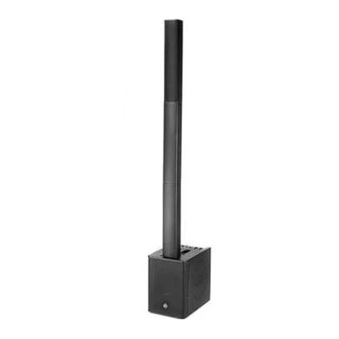
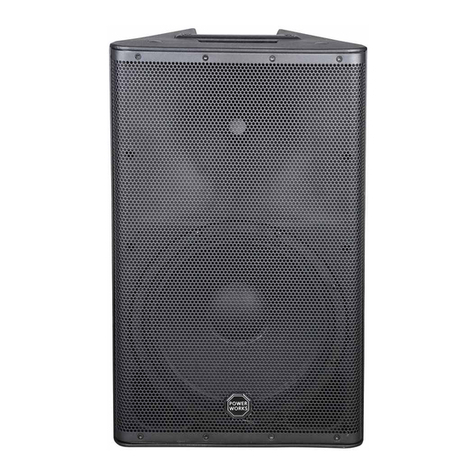
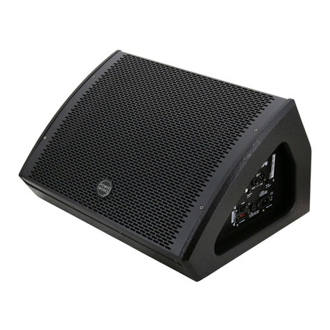
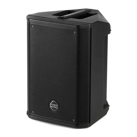
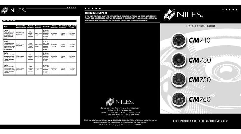
Power works ARTEMIS 08PD User manual

USER MANUAL
ARTEMIS 08PD
ARTEMIS 10PD
ARTEMIS 12PD
ARTEMIS 15PD
ARTEMIS 12P SUB
ARTEMIS 15P SUB
ARTEMIS 18P SUB

1
SAFETY INTRODUCTION
1.Please read the manual carefully and keep it for future reference.
2.All safety instructions and warnings must be adhered to. They are par t of the manual and must be kept
with the manual.
3.Any guarantee claims are rendered invalid if damage occurs due to non-observance of these operating
instructions. We assume no liability for any consequent damage.
4.We assume no liability for personal injury or damage to proper ty caused by incorrect handling or nono-
bservance of the safety instructions. Any guarantee claims expire in such cases.
5.Unauthorized conversions and/or modifications of the appliance are not permitted for safety and licensing
reasons (CE).
6.The appliance is approved for operation in dry, closed rooms only. Do not operate the device nearby water,
such as in bathrooms or nearby swimming pools.
7.The appliance may not be exposed to extreme temperatures (< +5°C / > +35°C) in operation.
8.The appliance may not be subjected to strong vibrations or heavy mechanical strain.
9.The appliance may not be exposed to excessive moisture (due to dripping or sprayed water, for example).
10.Do not place any recipients filled with liquids, such as glasses or vases, on top of or directly next to the
appliance. They could fall over, causing water to enter the appliance. Never pour out liquids above the
appliance. Do not place any small objects, such as coins or paper clips, on the appliance since they could
fall inside the appliance. You run a high risk of causing a fire or life-threatening electrocution! If any liquid
or objects enter the appliance never theless, pull the mains plug out of the socket immediately and contact
a specialist.
11.The appliance has been constructed according to protection class l. The power plug must only be plugged
into a protection class I outlet. The voltage and frequency must exactly be the same as stated on the device.
Wrong voltages or power outlets can lead to the destruction of the device and to lethal electrical shock.
12.110- 240 Vac, 50/60 Hz mains socket may be used as source of power for the appliance. Never try to operate
the appliance with any other voltage.
13.Only pull the mains plug out of the socket by the intended gripping surface. Do not pull it by the cable.
14.Never plug the mains plug in or out with damp or wet hands.
15.Always pull the mains plug out of the mains socket:
16.Before cleaning the appliance
17.If there is a thunderstorm
18.If you will not be using the appliance for a long period of time (>1 week)

2
19.Electrical appliances must be kept out of the reach of children. Be par ticularly careful if children are pre-
sent. Children are not aware of the hazards involved in handing electrical appliances improperly. Children
could attempt to poke objects into the appliance. There is a life-threatening danger of electrocution.
20.Do not leave the appliance unattended while operating it.
21.Never place the appliance on an unstable or movable surface. Persons could be injured or the appliance
damaged by it falling down.
22.When using a rack, make sure it is in a stable position and is transpor ted securely. Installation on uneven,
slanted surfaces or stopping the rack abruptly during transport can result in the rack over turning or applian-
ces falling from or out of the rack and injuring people.
23.Live components can be exposed by opening covers or removing components (unless this can be done wi-
thout tools). Contact points can also be live. If the appliance has to be opened in order to calibrate, service,
repair or replace components or assemblies, all of its poles must be disconnected from all sources of voltage
first. If the appliance has to be kept open and under voltage during maintenance or repairs, this work may only
be carried out by a specialist who is familiar with the risks involved and the relevant regulations.
24.Never connect the appliance directly after transferring it from a cold to a warm room. The condensation
water that forms could destroy the appliance or result in an electric shock. Allow the device to reach
room temperature before connecting it. Wait until the condensation water has evaporated. This can take
some hours.
25.Do not place any naked flames such as those of burning candles on or next to the appliance.
26.Do not place the appliance on soft surfaces such as carpets or beds. Do not cover the air vents of the
appliance. Do not obstruct the air circulation with objects such as magazines, table cloths or curtains. This
prevents the dissipation of heat from the appliance and can result in overheating.
27.Only use the appliance in a moderate climate, not in tropical environments.
28.All persons involved in operating, installing and servicing the appliance and putting it into service must be
trained and qualified accordingly and observe these operating instructions.
29.Defective mains cables may only be replaced by specialists. Danger of shock hazard!
30.Do not leave the packaging material lying around carelessly since it can become a source of danger for
children playing with it.
31.The accident prevention regulations and the regulations of the employers’ liability insurance association
should be observed at commercial institutions.
32.If you are not sure about the correct connection or if questions arise which are not answered by the
operating instructions, please do not hesitate to contact support or a specialist of your choice. Consult a
specialist if you are in doubt about the operating principle or the safety of the product.

3
2
5
1
3
4
78
9
6
ARTEMIS 8PD
ARTEMIS 10PD
ARTEMIS 12PD
ARTEMIS 15PD

4
LCD DSP Controls
An integrated LCD DSP control menu allows the user to select multiple DSP system settings on the loudspeaker.
To access the LCD DSP controls menu, do the following:
1. Push and hold the MASTER VOL knob to enter the LCD DSP controls menu.The LCD DSP Controls menu appears.
2. Turn the MASTER VOL knob to scroll through the menu items.
3. Push the MASTER VOL knob to select the menu item you want to modify.
The focus moves to the menu items on the right side of the LCD screen.
4. Turn the MASTER VOL knob to scroll through the menu items.
5. Push the MASTER VOL knob to confirm the selected menu items.
The setting is saved. The focus returns to the menu items on the left side of the LCD screen.
6. Repeat steps 2–5 to modify additional DSP & system settings.
7. Select EXIT to return to the home screen.
DSP
MASTER
PUSH FOR DSP
LEVEL 00dB
1.[DSP]-backlit display for DSP functions.
2.[ INPUT 1/INPUT 2]-Mic / Line input 1, designed as XLR / 1/4" combo socket, balanced.
3.[ AUX IN]-3.5 mm jack socket for connecting line level devices such as MP3 or CD players.
Stereo signals are combined.
4.[ OUTPUT]-Line output, designed as XLR chassis plug. The combined signal of both inputs is
present here, unaffected by DSP.
5.[ MASTER / PUSH FOR DSP]-Rotary control for the overall volume, push button for activating the DSP functions.
6.[ MAX INPUT 1/INPUT 2]-Rotary gain control for input 1. Turning clockwise increases the input gain for connec-
ting microphones. Turning counterclockwise decreases the input gain for connecting instruments or devices with
line level outputs.
7.[ IEC Socket with Fuse holder]-Plug the line cord into an AC socket properly configured for your particular
model. In case of fuse burn, to prevent the risk of fire and damaging the unit, Before replacing the fuse, make sure
the unit turned off and disconnected from the AC outlet.
8.[ POWER SWITCH]-Switch up to turn the speaker on, and switch down to turn it off. Make sure the level control is
down before you turn it on.
9.[VOLTAGE SELECT SWITCH]-Switch for setting the operating voltage. The mains voltage of your power supplier
and the operating voltage of the device must be the same!

2 5
1
3
4
6
7
8
9
5
ARTEMIS 12SUB
ARTEMIS 15SUB
ARTEMIS 18SUB

6
1.[DSP]-backlit display for DSP functions.
2.[ INPUT 1]-Line input 1, designed as XLR / 1/4" combo socket, balanced.
3.[ INPUT 2]-Line input 1, designed as XLR / 1/4" combo socket, balanced.
4.[ MASTER / PUSH FOR DSP]-Rotary control for the overall volume, push button for activating the DSP functions.
5.[ OUTPUT 1]-Line output, designed as XLR chassis plug. The combined signal of both inputs is
present here, unaffected by DSP.
6.[ OUTPUT 2]-Line output, designed as XLR chassis plug. The combined signal of both inputs is
present here, unaffected by DSP.
7.[ IEC Socket with Fuse holder]-Plug the line cord into an AC socket properly configured for your particular
model. In case of fuse burn, to prevent the risk of fire and damaging the unit, Before replacing the fuse, make sure
the unit turned off and disconnected from the AC outlet.
8.[ POWER SWITCH]-Switch up to turn the speaker on, and switch down to turn it off. Make sure the level control is
down before you turn it on.
9.[VOLTAGE SELECT SWITCH]-Switch for setting the operating voltage. The mains voltage of your power supplier
and the operating voltage of the device must be the same!
LCD DSP Controls
An integrated LCD DSP control menu allows the user to select multiple DSP system settings on the loudspeaker.
To access the LCD DSP controls menu, do the following:
1. Push and hold the MASTER VOL knob to enter the LCD DSP controls menu.The LCD DSP Controls menu appears.
2. Turn the MASTER VOL knob to scroll through the menu items.
3. Push the MASTER VOL knob to select the menu item you want to modify.
The focus moves to the menu items on the right side of the LCD screen.
4. Turn the MASTER VOL knob to scroll through the menu items.
5. Push the MASTER VOL knob to confirm the selected menu items.
The setting is saved. The focus returns to the menu items on the left side of the LCD screen.
6. Repeat steps 2–5 to modify additional DSP & system settings.
7. Select EXIT to return to the home screen.
DSP
MASTER
PUSH FOR DSP
LEVEL 00dB

7
The speakers have a stand flange with a 0° angle socket (rear position) and a socket with a 7° tilt angle (front posi-
tion). Examples of use:Use the socket with a 0° angle for standing audiences and the socket with a 7° tilt angle for
seated audiences.
STAND FLANGE
ARTEMIS 8PD
ARTEMIS 10PD
ARTEMIS 12PD
ARTEMIS 15PD
DUAL TILT FLANGE
0° 7°
DUAL POLE SOCKETS
ARTEMIS 12SUB
ARTEMIS 15SUB
ARTEMIS 18SUB
35mm diameter M20 screws.
Compatible with commercially available speaker poles of 35mm diameter and M20 screws.

8
Model:
Frequency response:
Type:
Coverage Angle
Max.SPL (Peak)
LF transducer
HF transducer
Pole Socket
Amplifier Type
Power output(RMS/peak):
Crossover frequency
Connectors Input
Connectors Output
Dimensions(WxHxD):
Weight:
ARTEMIS 8PD
Active PA Speaker
70Hz-19kHz
300W/600W
90° x 60°
120dB
8"Woofer 2"Voice coil
1" Exit-1.35" Compression Driver
Class D + Class AB
360 x 530 x 380 mm
13kg
3.5KHz
35mm With 1-way feature (0°-7°)
Input: 3.5mm Jack / XLR / 6.35mm TRS combo
Output: XLR
TECHNICAL SPECIFCATIONS
Active PA Speaker
65Hz-19kHz
350W/700W
90° x 60°
122dB
10"Woofer 2"Voice coil
1" Exit-1.35" Compression Driver
Class D + Class AB
3.2KHz
ARTEMIS 10PD
405 x 615 x 405 mm
17kg
Model:
Frequency response:
Type:
Coverage Angle
Max.SPL (Peak)
LF transducer
HF transducer
Pole Socket
Amplifier Type
Power output(RMS/peak):
Crossover frequency
Connectors Input
Connectors Output
Dimensions(WxHxD):
Weight:
ARTEMIS 12PD
Active PA Speaker
55Hz-19kHz
450W/900W
90° x 60°
124dB
12"Woofer 3"Voice coil
1" Exit-1.35" Compression Driver
Class D + Class AB
475 x 715 x 465 mm
22kg
2.8KHz
35mm With 1-way feature (0°-7°)
Input: 3.5mm Jack / XLR / 6.35mm TRS combo
Output: XLR
Active PA Speaker
45Hz-19kHz
500W/1000W
90° x 60°
126dB
15"Woofer 3"Voice coil
1" Exit-1.35" Compression Driver
Class D + Class AB
2.6KHz
ARTEMIS 15PD
525 x 815 x 510 mm
28kg

9
TECHNICAL SPECIFCATIONS
Model:
Frequency response:
Type:
Coverage Angle
Max.SPL (Peak)
LF transducer
HF transducer
Pole Socket
Power output(RMS/peak):
Crossover frequency
Connectors
Dimensions(WxHxD):
Weight:
ARTEMIS 8
2-Way passive speaker
70Hz-19kHz
350W/700W
90° x 60°
122dB
8"Woofer 2"Voice coil
1" Exit-1.35" Compression Driver
360 x 530 x 380 mm
9.6kg
3.5KHz
35mm With 1-way feature (0°-7°)
Lockable NL4 mounting connector
65Hz-19kHz
400W/800W
90° x 60°
124dB
10"Woofer 2"Voice coil
1" Exit-1.35" Compression Driver
3.2KHz
ARTEMIS 10
405 x 615 x 405 mm
15kg
Model:
Frequency response:
Type:
Coverage Angle
Max.SPL (Peak)
LF transducer
HF transducer
Pole Socket
Power output(RMS/peak):
Crossover frequency
Connectors
Dimensions(WxHxD):
Weight:
ARTEMIS 12
2-Way passive speaker
50Hz-19kHz
500W/1000W
90° x 60°
126dB
12"Woofer 3"Voice coil
1" Exit-1.35" Compression Driver
475 x 715 x 465 mm
20kg
2.8KHz
35mm With 1-way feature (0°-7°)
Lockable NL4 mounting connector
43Hz-19kHz
550W/1100W
90° x 60°
128dB
15"Woofer 3"Voice coil
1" Exit-1.35" Compression Driver
2.5KHz
ARTEMIS 15
525 x 815 x 510 mm
25kg
2-Way passive speaker
2-Way passive speaker

9
TECHNICAL SPECIFCATIONS
Model:
Frequency response:
Type:
Max.SPL (Peak)
LF transducer
Pole Socket
Power output(RMS/peak):
Weight:
ARTEMIS 12SB
Active PA Subwoofer
40Hz-150Hz
800W/1600W
128dB
12"Woofer 3"Voice coil
32kg
35mm diameter and M20 screws
Amplifier Type Class D
Connectors Input
Connectors Output
Input: 2 x XLR/TRS combo jacks
Output: 2 x XLR link outputs
ARTEMIS 15SB
Active PA Subwoofer
35Hz-150Hz
1000W/2000W
132dB
15"Woofer 4"Voice coil
45kg
Class D
ARTEMIS 18SB
Active PA Subwoofer
30Hz-150Hz
1000W/2000W
134dB
18"Woofer 4"Voice coil
53kg
Class D
Model:
Frequency response:
Type:
Max.SPL (Peak)
LF transducer
Pole Socket
Power output(RMS/peak):
ARTEMIS 12S
40Hz-500Hz
800W/1600W
128dB
12"Woofer 3"Voice coil
35mm diameter and M20 screws
ARTEMIS 15S
35Hz-500Hz
1000W/2000W
132dB
15"Woofer 4"Voice coil
ARTEMIS 18S
30Hz-500Hz
1000W/2000W
134dB
18"Woofer 4"Voice coil
Connectors
Dimensions(WxHxD):
Weight:
Lockable NL4 mounting connector
500 x 680 x 640 mm
29kg
710 x 720 x 575 mm
43kg
775 x 790 x 655 mm
51kg
Passive Subwoofer Passive Subwoofer Passive Subwoofer
Dimensions(WxHxD): 500 x 680 x 640 mm 710 x 720 x 575 mm 775 x 790 x 655 mm

Version 1.0
This manual suits for next models
6
Table of contents
Other Power works Speakers manuals
Popular Speakers manuals by other brands
Triad Speakers
Triad Speakers OnWall MicroLCR 3.0 installation manual
Hifonics
Hifonics ZS35CX Quick start installation guide
Bg
Bg Radia Series R-800 Specifications

Better Music Builder
Better Music Builder CLASSIC Series owner's manual

Philips
Philips Fidelio DS3800W brochure

Bush
Bush Wi-768 instruction manual
