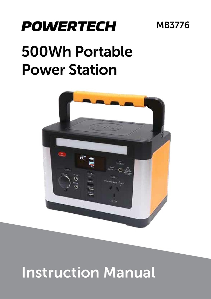
PowerTech HB8506 User manual

Instruction Manual
Portable Battery Box
Power Station
with Integrated 25A DCDC Charger
HB8506

2
• For charging 12V rechargeable batteries only.
• Never attempt to recharge non-rechargeable batteries.
• The lid of the battery box must remain shut at all times while charging a battery
or powering a device from an outlet.
• Do not allow any metal objects to fall into the battery box or enter any of the
ports.
• Never insert anything other than a compatible electrical plug into any of the
ports on the battery box.
• Ensure that the battery box is shut and the screws are tight before powering
any devices.
• Do not try to jumpstart when using lithium batteries.
IMPORTANT SAFETY INSTRUCTIONS:
PRODUCT OVERVIEW:
CIGARETTE
SOCKET

3
ACCESSORIES:
Step 1: Peel o the plastic film to expose
the non-slip surface of the silicone pads.
Step 3: Secure the battery in place by
fastening the buckle over the battery
pads.
Step 4: Install the battery cables onto
the terminal posts of the battery.
Ensure the red cable is connected to
the positive(+) terminal and both black
cables connected to the negative(-)
terminal. Tighten firmly but be sure not
to over-tighten the battery terminals.
Step 2: Place your battery carefully into
the battery box base, positioning it as
centrally as you can on the non-slip
pads.
Note: the pads may be washed to regain stickiness

4
BATTERY TO USE:
Max.Battery Dimensions: 340mm x 185mm W x 235mm H (with Silicone Mat)
Max.Battery Weight: 35kg
Supported Chemistries: AGM, Calcium, Wet, Gel or Lithium LiFePO4
(Deep Cycle Bateries)

5
WIRING DIAGRAM:

6
SWITCH/BUTTONS:
The Master Switch
The master switch disconnects everything (except for the large 175 amp High
Current Connectors) from the battery including the DC-DC Charger. Tuming it o is
a quick way to disconnect all devices to ensure your battery is not being drained.
Note: The DC-DC Charger and Solar Regulator cannot charge the internal battery
while the Master Switch is in the OFF position, nor can an external battery. If
another, external battery is connected through one of the IN/OUT connectors,
the DC-DC is able to charge that battery, even with the Master Switch in the OFF
position-bypassing the internal battery.
The Voltmeter
The inbuilt voltmeter will display the voltage of your battery. For an accurate voltage
reading, disconnect all loads and charging sources from the power station and test.
Note: The battery voltage table on the top sticker of the battery box is to be used
as a guide only, check your battery specifications if you want to be precise.

7
CONNECTIONS:
Outputs
Outputs
3 X Cigarette Socket Outputs
• Maximum 15A output per socket
2 X Dual USB Outputs
• 1 x 4.2A High Powered USB
• 1 x QC3.0+2.4A USB Output
Benefits of Quick Charge Q
When paired with compatible devices, a Quick Charge-enabled charger delivers
more power, allowing the connected device to charge faster. As one of the most
widely used of the fast charging technologies, Quick Charge is already in many of
your favorite smartphones. If your smartphone is Quick Charge 3.0-compatible, you
can charge up to 80% in just 35 minutes. To future-proof your chargers, each new
Quick Charge generation is backwards compatible, meaning it will work with the
generations that came before.
6 X (50A) High Current Connectors
• Input/Output Capable.
• All High Current Connectors combined must not exceed 50A total current.
WARNING:
• Do not plug in multiple chargers as inputs.
• Do not use an external charger while the DC-DC Charger is operating.
• Exceeding 50A combined current rating will trigger the safety breaker.
Safety breaker will auto-reset in time.

8
NOTE: THE 6 HIGH CURRENT CONNECTORS INDICATED CANNOT EXCEED A
TOTAL OF 50 AMPS COMBINED.
1X (175A) High Current Connectors
• High Current Inverter Output
• Emergency 600A Jump Starter
Output (7 seconds)
• Connected directly to battery
WARNING:
• The Master switch does not
disconnect the battery from this
connector.
• This output is NOT Fused or Short
Circuit Protected.
• Do not jump start a vehicle for longer
than 7 seconds.
• Deep Cycle batteries should be
used for jump starting in emergency
situations ONLY, as it will aect the
battery life.
• Check battery specifications and
compatibility with high current draw
before using the jump start connector.
• Lithium batteries should not be used
for jump starting.
CONNECTIONS:

9
Inputs
Alternator
1 X Triple High Current Connectors
• 9-32V DC Starter Battery Input(+/-)
• Ignition source connection
MPPT Solar
1 X (50A) High Current Connectors
• Minimum Solar Input Voltage: 9V DC
• Maximum Solar Input Voltage: 23V DC
• Maximum Solar Input Current: 25A
Unregulated Solar Input-utilises the inbuilt DC-DC MPPT regulator.
Not suitable for regulated solar input, connect to a standard in/out connector when
using an external or panel-mounted solar controller/regulator.
WARNING:
• Do not exceed the Maximum Voltage of 23V DC
• Do not exceed the Maximum Input Current of 25A
CONNECTIONS:

10
CONNECTION DC-DC CHARGER:
The 12V BATTERY BOX includes a built-in DC-DC Charger suitable for charging
from a vehicle alternator.
The easiest way to connect the Power Station to your vehicle is by using the Plug &
Play Wiring Kit (sold separately).
The triple High Current connector fitted to the Battery Box interfaces with the Plug
& Play Wiring Kit, providing a simple, quick release vehicle charging solution. This
triple connector and cable provides alternator power to the DC-DC on the Power
Station, along with an Ignition Source for charging in vehicles that are fitted with
Smart or Temperature Compensating Alternator.

11
DC-DC CHARGER GUIDE:
Understanding Solar, Alternator & Charging Lights
Alternator LED Battery Status
Alternator LED Battery Status Within Ignition Wire Connected
Solar LED Status
NOTE:
• Alternator has priority over solar therefore, if both solar and the alternator are
connected, only alternator LED is Solid and the alternator is charging.
• 30 second delay between the cut-in voltage being reached and charging beginning
and a 60 second delay before disconnecting when under cut-out voltage.
Voltage 12V Voltage 24V LED Status
0-8.9 Volts 12-17.9 Volts OFF Under operating
voltage
9-12.6 Volts 18-25.2 Volts Flash 1 sec on 5 sec o Under cut-out voltage
12.7-13.1 Volts 25.3-26.3 Volts Flash 1 sec on 1 sec o Under cut-in voltage
13.2 Volts 26.4 Volts Solid On
Cut-in voltage reached
charging will start after
30 sec delay
Voltage 12V Voltage 24V LED Status
0-8.9 Volts 12-17.9 Volts OFF Under operating
voltage
9-11.6 Volts 18-23.2 Volts Flash 1 sec on 5 sec o Under cut-out voltage
11.7-12.1 Volts 23.3-24.3 Volts Flash 1 sec on 1 sec o Under cut-in voltage
12.2 Volts 24.4 Volts Solid On
Cut-in voltage reached
charging will start after
30 sec delay
Solar Voltage LED Status
0-8.9 Volts OFF Under cut-in voltage
Unregulated 9-23V DC Solid ON
Cut-in voltage reached charging will
begin after 10 sec delay
(please note alternator has priority over solar)
23V Solar LED is O
Stage 1&3 LED Fault Code Indication Solar input Voltage Exceeded

12
DC-DC CHARGER GUIDE:
Choosing the battery type:
Charging Stage Profile
Lithium BMS Sleep Mode & Recovery Feature
Most lithium batteries are built with a Battery Management System (BMS) inside to
protect the battery from overcharging, overdischarging and extreme temperature
changes. One of the key functions of the BMS is to protect your battery by
internally disconnecting the load’ when voltage drops below specific parameters,
this will then result in the battery entering a “sleep” mode. 1 (Load includes any
accessories and/or device(s) drawing charge from the battery. (Eg. fridges, pumps,
food sealers, etc) The DC-DC MPPT Solar Battery Charger has a lithium battery
recovery function. This function has been designed to recover lithium batteries
from sleep mode.
Lithium Battery Sleep Mode Indication:
When the lithium battery has entered sleep mode, the charger will show fault
codes for output open circuit, until all loads’ are disconnected and a sucient
charge source is connected.
Stage Description
Bulk
GEL
100% Current
until 14.1V
AGM
100% Current
until 14.4V
WET
100% Current
until 14.7V
Calcium
100% Current
until 15.4V
Lithium
100% Current
until 14.4V
Absorption Constant 14.1V
Until 3.8A
Constant 14.4V
Until 3.8A
Constant 14.7V
Until 3.8A
Constant 15.4V
Until 3.8A
Constant 14.4V
Until 3.8A
Float 13.7V at 100% Current Max
Pulse
Begins after a continuous float stage of 10 days and pulses power through the battery
using the same current and voltage as the absorption stage to maintain charge.
During this PULSE time, if the voltage of the auxiliaty battery drops below 12.6V, the
charger will restart the charge cycle at Bulk. Once pulse is completed, the charger
reverts to float stage.
The default battery setting is AGM.
When the auxiliary battery is connected, press and hold the mode button for
5 seconds or until the battery light starts flashing. Then select from either GEL,
AGM,WET,CALCIUM or LITHIUM and wait for the battery light to stop flashing.
When this occurs, your selection is saved.
NOTE: When in the float stage, the battery is fully charged. At the “float stage”,
when the battery voltage drops to 12.7 volts, the charger will restart charging
from the “bulk” stage.

13
DC-DC CHARGER GUIDE:
IMPORTANT: You must select ‘LITHIUM’ as the battery type by using the ‘MODE’
button prior to connecting it to a lithium battery in sleep mode to attempt
recovery.
How to Wake a Lithium Battery to Begin Recovery Mode
1. Disconnect any load connected to the lithium battery.
2. Connect Alternator Input or Solar Input? to the DC-DC MPPT Solar Battery
Charger.
3. Connect the output from the DC-DC charger to the lithium battery. The Charger
will have all battery types (GEL,AGM,WET CALCIUM,LITHIUM) flashing and the
BULK and PULSE LED lights will remain on for 30 seconds (as indicated in diagram
above,) before entering Recovery Mode. (Alternator and Solar inputs must be
above the cut-in voltage for DC-DC Charger)
Recovery Mode Indicator
When the lithium battery has entered recovery mode, the DC-DC MPPT Solar
Battery Charger display will have the source indicator illuminate(eg;SOLAR) and
the battery type LITHIUM will be flashing. See the diagram below.
When the battery voltage has been recovered to 12V, the DC-DC charger will
automatically change to normal stage charging programs and loads may be
reconnected.

14
DC-DC CHARGER GUIDE:
Fault Codes
If all battery type selection lights are flashing simultaneously please see
troubleshooting guide below.
There are error codes that may be displayed. These will be displayed in the
following way:
Stage LED S1 S2 S3 S4 Cause Remedy
Solar input
high voltage XOutput voltage is
detected at solar input
Check solar panel open
circuit voltage
Solar input
reverse XSolar input is reversely
connected
Check solar input
connection
Alternator
high voltage XOvervoltage is detected at
alternator input
Check vehicle battery
voltage
Alternator
input reverse X X Alternator input is
reversely connected
Check alternator input
connection
Output fault
mode X
Output battery is reversely
connected
Check output cable
connection
Overvoltage is detected
at output
Check auxiliary battery
voltage
Output open circuit or
dead battery
Check auxiliary battery
voltage & cable
connections

15
TECHNICAL SPECIFICATIONS:
Battery Box Information
Material ABS
Tempetature Range -10°C - 60°C+
Battery Information
Supported Chemistries AGM, Calcium, Wet, Gel or Lithium (Deep Cycle Only)
MAX Battery Dimensions 340mm L x 185mm W x 235mm H (with Silicone Mat)
MAX Battery Weight 35kg
Ports (Input/Output)
6 x (50A) High Current
Connectors
Input/Output Capable
Maximum Combined 50A Current Rating
WARNING:
1. Do not plug in multiple chargers as inputs
2. Do not use an external charger while the DC-DC Charger is
operating
3. Exceeding 50A combined current rating will trigger the
safety breaker
1 x (175A) High Current
Connectors
High Current Inverter Output
WARNING:
1. Master switch does not disconnect the battery from this
connector
2. This output is NOT Fused or Short Circuit Protected
3. Do not jump start a vehicle for longer than 7s
4. Deep cycle batteries should be used for jump starting in
emergency situations ONLY, as it will aect battery health
5. Check battery specifications and compatibility with high
current draw before using jump start connector
6. Lithium batteries should not be used in this box when
intending to jump start
3 x Cigarette Socket
Outputs Maximum 15A output per socket
2 x Dual USB Outputs 1 x 4.2A Standard USB Output
1 x QC 3.0+2.4A USB Output
Alternator Input
1 x Triple High Current
Connectors
9-32V DC Starter Battery Input (+/-)
Ignition Override input (I)
Solar Input
1 x (50A) High Current
Connectors
Minimum Solar Input Voltage: 9V DC
Maximum Solar Input Voltage: 23V DC
Maximum Solar Input Current: 25A
WARNING:
1. Do not exceed the Maximum Voltage of 23V DC
2. Do not exceed the Maximum Input Current of 25A

16
FREQUENTLY ASKED QUESTIONS:
Q. What types of batteries can | charge with this battery box?
The battery box is compatible with most 12V deep cycle batteries. This includes
AGM, Calcium, Wet, Gel or Lithium LiFePO4.
Q. If storing my 12 Power Box for long periods, what should I do to look after
my battery’s health?
An AGM battery is best stored fully charged. The 12V Power Box is fitted with
a Master Switch that allows all to be disconnected from the battery for storage
-meaning nothing can drain the battery over time.
For short term storage we recommend fully charging the battery with a 240V
mains charge, before switching o the Master Switch and storing.
For longer term storage, we recommend instead connecting a 240V mains
charger to the battery in order to continually maintain a full state of charge-this
process is called trickle charging.
Q. Is the Power Station waterproof?
The 12V Power Box has been designed to be as resistant to moisture and
dust as possible, though it is not waterproof.
Do not leave exposed to rain or weather, and do not submerge.


Distributed by:
Electus Distribution Pty Ltd
46 Eastern Creek Dr,
Eastern Creek NSW 2766 Australia
Ph 1300 738 555
Int’l +61 2 8832 3200
Fax 1300 738 500
www.electusdistribution.com.au
Table of contents
Other PowerTech Portable Generator manuals
Popular Portable Generator manuals by other brands
AIDA
AIDA TGEN-6P Operation guide

Schmalz
Schmalz ECBPMi UR operating instructions
Scheppach
Scheppach DGS5500 Translation of original instruction manual

American Rescue Technology
American Rescue Technology ART-10K258 instruction manual

Sportsman
Sportsman GEN2K Step-By-Step Quick Start Guide
Fischer Panda
Fischer Panda Panda 5000i PMS manual
