Schmalz ECBPMi UR User manual

Electrical Vacuum Generator ECBPMi
Operating Instructions
WWW.SCHMALZ.COM EN-US · 30.30.01.02196 · 01 · 11/20

Note
The Operating instructions were originally written in German. Store in a safe place for future reference.
Subject to technical changes without notice. No responsibility is taken for printing or other types of er-
rors.
Published by
© J.SchmalzGmbH, 11/20
This document is protected by copyright. J.SchmalzGmbH retains the rights established thereby. Repro-
duction of the contents, in full or in part, is only permitted within the limits of the legal provisions of
copyright law. Any modifications to or abridgments of the document are prohibited without explicit writ-
ten agreement from J.SchmalzGmbH.
Contact
J. Schmalz GmbH
Johannes-Schmalz-Str. 1
72293 Glatten, Germany
T: +49 7443 2403-0
www.schmalz.com
Contact information for Schmalz companies and trade partners worldwide can be found at:
www.schmalz.com/salesnetwork
2 / 56 EN-US · 30.30.01.02196 · 01 · 11/20

Contents
EN-US · 30.30.01.02196 · 01 · 11/20 3 / 56
Contents
1 Important Information ...................................................................................................................................6
1.1 Note on Using this Document ............................................................................................................ 6
1.2 The technical documentation is part of the product ........................................................................ 6
1.3 Type Plate ............................................................................................................................................ 6
1.4 Warnings in This Document................................................................................................................ 7
1.5 Symbol.................................................................................................................................................. 7
2 Fundamental Safety Instructions...................................................................................................................8
2.1 Intended Use........................................................................................................................................ 8
2.2 Non-Intended Use ............................................................................................................................... 8
2.3 Personnel Qualification....................................................................................................................... 8
2.4 Modifications to the Product.............................................................................................................. 8
3 Product Description ........................................................................................................................................9
3.1 Design of the ECBPMi ......................................................................................................................... 9
3.2 Display and Control Elements........................................................................................................... 10
3.2.1 Description of the Display and Control Elements.................................................................... 10
3.2.2 Operation with Gloves ..............................................................................................................10
3.2.3 LED State Indicators...................................................................................................................11
3.2.4 Vacuum Level Indicator............................................................................................................. 12
4 Technical Data ...............................................................................................................................................13
4.1 Electrical Parameters ......................................................................................................................... 13
4.2 Mechanical Data................................................................................................................................ 13
4.2.1 General Parameters ................................................................................................................... 13
4.2.2 Mechanical Performance Data..................................................................................................14
4.2.3 Dimensions................................................................................................................................. 15
4.2.4 Maximum Torque ......................................................................................................................15
4.2.5 Factory Settings ......................................................................................................................... 15
5 Description of Functions...............................................................................................................................16
5.1 Control Scheme ................................................................................................................................. 16
5.2 Depositing the Workpiece ................................................................................................................ 16
5.3 Interfaces ........................................................................................................................................... 16
5.3.1 Basic Principles of IO-Link Communication.............................................................................. 16
5.3.2 Process Data ............................................................................................................................... 16
5.3.3 ISDU Parameter Data................................................................................................................. 17
5.3.4 Near Field Communication (NFC) .............................................................................................17
5.4 Lifting the Workpiece ....................................................................................................................... 18
5.5 Automatic Operation ........................................................................................................................ 18
5.6 Monitoring the System Vacuum and Displaying the Control Value [0x0040] ............................... 18
5.7 Setting the Vacuum Limit Value H2 ................................................................................................. 19
5.8 Calibrating the Vacuum Sensor [0x0002]......................................................................................... 20
5.9 Control Function................................................................................................................................ 20
5.9.1 Sustained Suction ...................................................................................................................... 20
5.9.2 Control ....................................................................................................................................... 20
5.10 Blowoff Modes [0x0045] ................................................................................................................... 21
5.10.1 Externally Controlled Blowoff ..................................................................................................21
5.10.2 Internally Time-controlled Blowoff .......................................................................................... 22
5.10.3 Externally Time-controlled Blowoff ......................................................................................... 22
5.10.4 Setting the Blowoff Time.......................................................................................................... 22

Contents
4 / 56 EN-US · 30.30.01.02196 · 01 · 11/20
5.11 Output and Input Signals.................................................................................................................. 22
5.11.1 Signal Inputs .............................................................................................................................. 22
5.11.2 Signal Outputs ...........................................................................................................................22
5.11.3 Signal Type................................................................................................................................. 23
5.12 Activating a Freedrive Request......................................................................................................... 23
5.13 Switch-Off Delay [0x004B] ................................................................................................................ 24
5.14 Device Functions................................................................................................................................ 24
5.14.1 Restricting Access Using Device Access Locks [0x000C] ........................................................... 24
5.14.2 Restricting Extended Access with Extended Device Access Locks [0x005A] ........................... 24
5.15 Resetting the Device to the Factory Settings................................................................................... 24
5.16 Counter(s) .......................................................................................................................................... 25
5.17 Displaying Errors and Warnings ....................................................................................................... 26
5.17.1 Displaying Errors........................................................................................................................ 26
5.17.2 Display of Warnings .................................................................................................................. 27
5.17.3 Temperature Display [0x0044] .................................................................................................. 27
5.17.4 Monitoring the Supply Voltages [0x0042] ............................................................................... 28
5.18 Energy and Process Control (EPC)..................................................................................................... 28
5.18.1 Condition Monitoring (CM) [0x0092] ....................................................................................... 28
5.18.2 Energy Monitoring (EM) [0x009D]............................................................................................ 31
5.18.3 Predictive Maintenance (PM) ................................................................................................... 31
5.19 Production Setup Profiles ................................................................................................................. 32
5.20 Device Data........................................................................................................................................ 32
5.21 User-Specific Localization ................................................................................................................. 32
5.22 Robot-specific Device Data ............................................................................................................... 33
5.23 Device Status...................................................................................................................................... 33
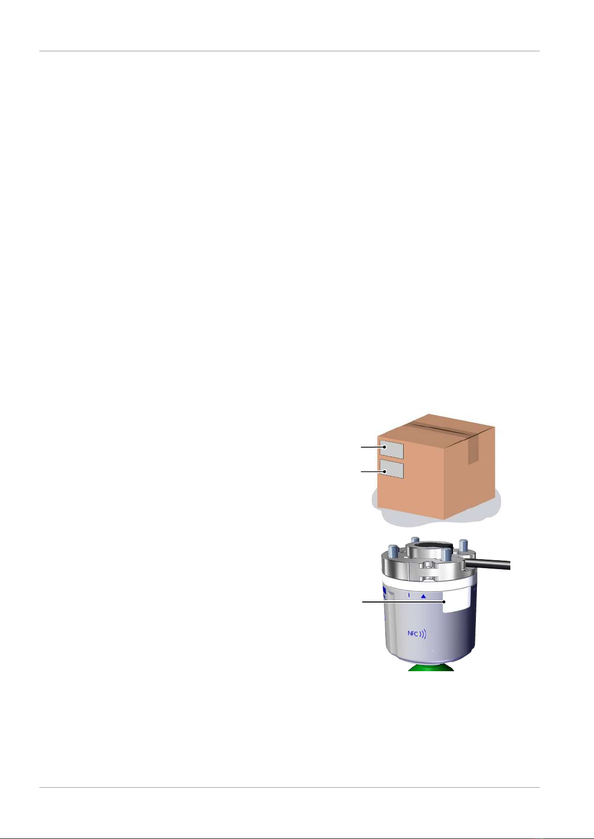
6 Transport and Storage..................................................................................................................................34
6.1 Checking the Delivery ....................................................................................................................... 34
7 Installation.....................................................................................................................................................35
7.1 Installation Instructions..................................................................................................................... 35
7.2 Mechanical Attachment.................................................................................................................... 35
7.3 Compatibility ..................................................................................................................................... 36
7.4 Description of the Electrical Connection ......................................................................................... 37
7.5 Start of Operations............................................................................................................................ 40
8 Operation ......................................................................................................................................................41
8.1 Hazard during Operation ................................................................................................................. 41
8.2 Preparations....................................................................................................................................... 41
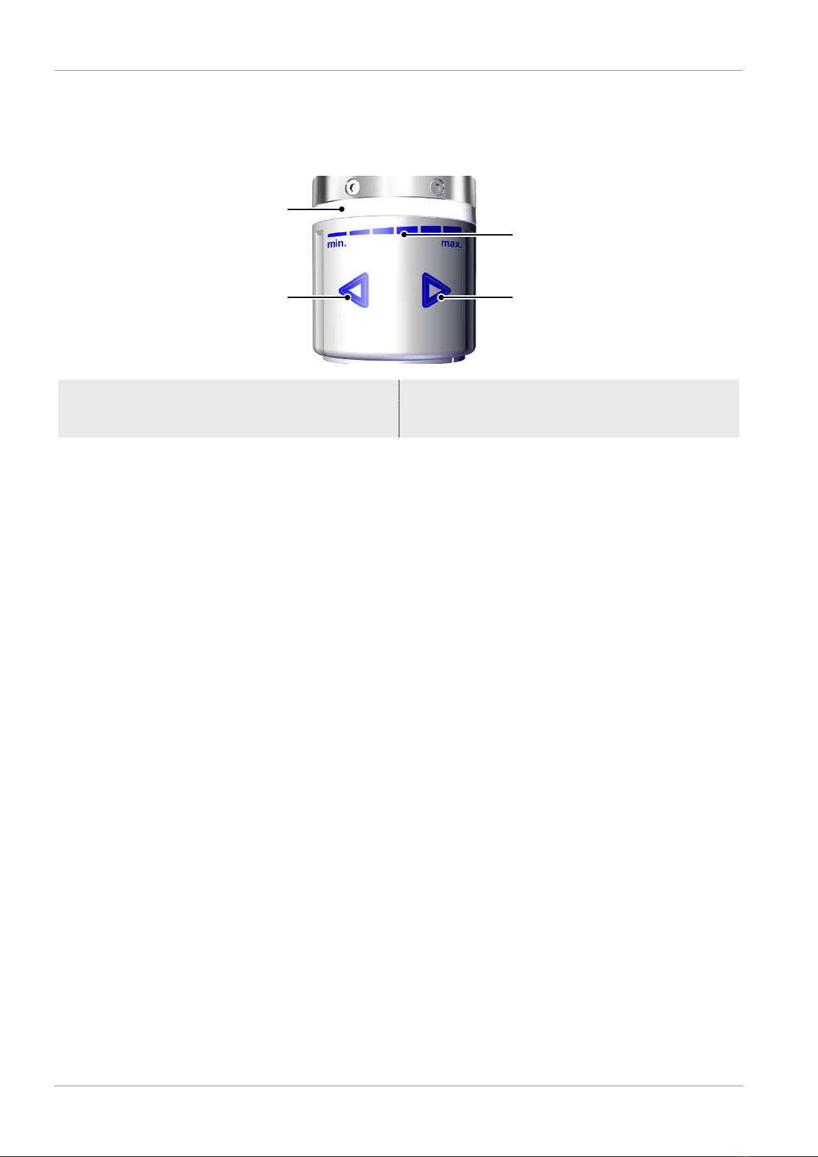
8.3 Operating Modes .............................................................................................................................. 41
8.3.1 SIO Operating Mode ................................................................................................................. 42
8.3.2 IO-Link Operating Mode ........................................................................................................... 42
8.3.3 Operating Mode RS-485............................................................................................................ 42
9 Maintenance..................................................................................................................................................43
9.1 Safety ................................................................................................................................................. 43
9.2 Cleaning the Device .......................................................................................................................... 43
9.3 Cleaning the Sieve Insert .................................................................................................................. 43
9.4 Replacement of the Device with a Parameterization Server.......................................................... 43
10 Warranty........................................................................................................................................................44
11 Troubleshooting............................................................................................................................................45

Contents
EN-US · 30.30.01.02196 · 01 · 11/20 5 / 56
12 Spare and Wearing Parts, Accessories.........................................................................................................46
13 Disposing of the Device................................................................................................................................47
14 Appendix .......................................................................................................................................................48
14.1 EC Declaration of Conformity........................................................................................................... 48
14.2 ECBPMi Data Dictionary_21.10.01.00140_00.PDF............................................................................ 49

Important Information
6 / 56 EN-US · 30.30.01.02196 · 01 · 11/20
1Important Information
1.1Note on Using this Document
J.SchmalzGmbH is generally referred to as Schmalz in these Operating instructions.
These Operating instructions contain important notes and information about the different operating
phases of the product:
• Transport, storage, start of operations and decommissioning
• Safe operation, required maintenance, rectification of any faults
The Operating instructions describe the product at the time of delivery by Schmalz.
1.2The technical documentation is part of the product
1. For problem-free and safe operation, follow the instructions in the documents.
2. Keep the technical documentation in close proximity to the product. The documentation must be ac-
cessible to personnel at all times.
3. Pass on the technical documentation to subsequent users.
ðFailure to follow the instructions in these Operating instructions may result in injuries!
ðSchmalz is not liable for damage or malfunctions that result from failure to heed these instructions.
If you still have questions after reading the technical documentation, contact Schmalz Service at:
www.schmalz.com/services
1.3Type Plate
The type plates (1) and (2) are attached to the packag-
ing.
The type plate (1) contains data for the robot set:
• Name
• Article/part number
The type plate (2) contains data for the Mini-Cobot-
Pump ECBPMi:
• Name
• Article/part number
• Manufacturing date
• Serial number
• QR code
• CE label
• Voltage range
• IO-Link symbol
The type plate (3) is permanently attached to for the
Mini-CobotPump (which is referred to below as the
ECBPMi ) and must always be clearly legible. It contains
the same data as the type plate (2).
3
1
2
Please specify all the information above when ordering replacement parts, making warranty claims or for
any other inquiries.

Important Information
EN-US · 30.30.01.02196 · 01 · 11/20 7 / 56
1.4Warnings in This Document
Warnings warn against hazards that may occur when handling the product. This document contains three
levels of danger that you can recognize by the signal word.
Signal word Meaning
WARNING Indicates a medium-risk hazard that could result in death or serious injury if
not avoided.
CAUTION Indicates a low-risk hazard that could result in minor or moderate injury if not
avoided.
NOTE Indicates a danger that leads to property damage.
1.5Symbol
This symbol indicates useful and important information.
üThis symbol represents a prerequisite that must be met prior to an operational step.
4This symbol represents an action to be performed.
ðThis symbol represents the result of an action.
Actions that consist of more than one step are numbered:
1. First action to be performed.
2. Second action to be performed.

Fundamental Safety Instructions
8 / 56 EN-US · 30.30.01.02196 · 01 · 11/20
2Fundamental Safety Instructions
2.1Intended Use
The ECBPMi is built in accordance with the latest standards of technology and is delivered in a safe oper-
ating condition; however, hazards may arise during use.
The ECBPMi is designed to generate a vacuum for gripping and transporting objects when used in con-
junction with suction cups. The pump is designed to be connected to a PLC or a robot control unit.
It has been specially developed for use in collaborative robot systems.
Non-aggressive and flammable gases and dry and oil-free air (no graphite) are permitted as the media to
be evacuated.
Schmalz URCap (V2.0.1) can be used from Polyscope 3.12 (for UR series) or Polyscope 5.5. (for URe series)
Note: Version not downward compatible
Intended use includes observing the technical data and the installation and operating instructions in this
manual.
2.2Non-Intended Use
Schmalz does not accept any liability for any direct or indirect losses or damages that result from using
the product. This applies, in particular, to any use of the product that is not in accordance with the in-
tended purpose and to any use that is not described or mentioned in this documentation.
2.3Personnel Qualification
Unqualified personnel cannot recognize dangers and are therefore exposed to higher risks!
1. Only instruct qualified personnel to perform the tasks described in this manual.
2. The product may only be operated by persons who have undergone appropriate training.
3. Electrical work and installations may only be carried out by qualified electrical specialists.
4. Assembly and maintenance work may only be carried out by qualified personnel.
The following target groups are addressed in this manual:
• Installers who are trained in handling the product and can operate and install it
• Technically trained service personnel performing the maintenance work
• Technically trained persons who work on electrical equipment
2.4Modifications to the Product
Schmalz assumes no liability for consequences of modifications over which it has no control:
1. The product must be operated only in its original condition as delivered.
2. Use only original spare parts from Schmalz.
3. The product must be operated only in perfect condition.

Product Description
EN-US · 30.30.01.02196 · 01 · 11/20 9 / 56
3Product Description
3.1Design of the ECBPMi
13
12
7
14
11
4
6
1
2
3
8
9
16
15
3
5
10
1 Housing of ECBPMi 2 LED status indicator, 360° RGB circumfer-
ential light
3 Customer-specific robot connection flange 4 Electrical connection, connection cable
with robot-specific length and connection
plug
5 Fastening screw for the robot, 4x M6x10 6 Fastening screw for the customer-specific
robot connection flange, 2x M3x14
7 Thread insert, 4x M4 female thread 8 Marking for the alignment of the op-
tional VEE flange 1)
9 Touch capacitive button, 2x 10 Vacuum display field, segmented LED dis-
play in the front section
11 Bayonet fastener position indicator 12 NFC symbol
13 Ventilation opening 14 Vacuum connection with G1/4" female
thread
15 Pin spring contact for the flange 16 ECBPMi PNP/NPN setting for the inputs
and the output OUT2
1) When mounting the VEE flange, the side marking on the ECBPMi (8) must align with the marking on
the flange.

Product Description
10 / 56 EN-US · 30.30.01.02196 · 01 · 11/20
3.2Display and Control Elements
3.2.1Description of the Display and Control Elements
1
2
3
4
1 “Less” touch capacitive button 2 LED illuminated ring
3 Vacuum scale, min. 100mbar to max.
600mbar
4 “More” touch capacitive button
The ECBPMi is operated using two touch capacitive buttons.
The buttons are used to set the limit value H2 (“Part Present”). When this limit value is exceeded, the digi-
tal output OUT2 is activated.
The LED illuminated ring conveys various status information and the vacuum level is shown in the front
section when adjusting the limit value.
When the power supply is switched on, the touch capacitive buttons self-calibrate. The buttons should not
be touched at this time.
3.2.2Operation with Gloves
The sensitivity of the touch capacitive buttons is designed in such a way that the relevant button is acti-
vated only if the housing is touched during operation with the finger or hand. However, it can also be op-
erated with a variety of thin or special gloves.
Wear gloves made from cotton or gloves with touch-sensitive surfaces with the capacitive touch feature.
Do not use thick gloves to operate the touch-sensitive buttons.
If the buttons do not respond while you are wearing gloves, please remove the gloves and try again with-
out them.

Product Description
EN-US · 30.30.01.02196 · 01 · 11/20 11 / 56
3.2.3LED State Indicators
The integrated LED status indicators show the current process statuses.
The ECBPMi has two LED areas for displaying the status.
The table below explains the meaning of the LEDs:
360° status indicator LEDs ECBPMi status
All lights are off. No power supply
The device is inactive
Default color
Green light remains illuminated, re-
duced brightness
Green light remains illuminated,
bright
Default status:
“Part Present” status:
The brightness of the status lights lets you
immediately identify whether the “Part
Present” limit value is fallen below or ex-
ceeded.
Ready,
vacuum < H2 (vacuum has fallen below
“Part Present” limit value), OUT2 is deac-
tivated
Vacuum limit value H2 is reached, vacuum
> H2, output OUT2 is activated
Blue light, circulating
Blue light, flashing
Freedrive:
The robot arm is free to move to a new
position, output OUT3 is activated.
The set value has been saved.
Yellow light, which illuminates sec-
tion by section
Pulsing yellow light
Initiating “Reset to factory settings” via
manual operation
Performing “Reset to factory settings”
Orange light remains illuminated
Orange light, flashing
Warnings have been issued
The set value was not saved.
Red light pulsing
1x supply voltage error
2x temperature error
3x pump error
For more information, see (> See ch. Dis-
playing Errors,Page 26)

Product Description
12 / 56 EN-US · 30.30.01.02196 · 01 · 11/20
Adjusting the color and brightness of the “Part Present” LED status display
The green light to indicate “Part Present” status is selected in the default settings.
“Part Present” status can be adjusted in IO-Link mode in terms of color and brightness. Individual settings
can be configured for “Ready” status, “Vacuum < H2” as well as the status “Vacuum limit value H2”
reached, “Vacuum > H2.”
The “Color-Profile” parameter [0x0052] can then be used to define color tone (RGB) and brightness for
the above-mentioned statuses using four bytes each.
The brightness setting has no influence on the color tone. I.e. when the brightness changes, the perceived
brightness is changed — not the color, the color tone remains the same.
The “System Command” parameter [0x0002] can be used to reset the LED settings to the factory settings
(default values) using the 0xAC command.
3.2.4Vacuum Level Indicator
Above the printed scale on the front, six LEDs indicate the vacuum level of the vacuum limit value H2 for
the “Part Present” check, in a range of 100 to 600mbar.
Illuminated display with 6 LEDs
The indicator for the vacuum level that is currently set is activated using one of the buttons.
The vacuum limit value can be increased or lowered either by tapping or holding down the two touch ca-
pacitive buttons.
The scale shows a range of 100 (min.) to 600mbar (max.) (100mbar per LED). It can be adjusted in
10mbar increments.
The example above shows a vacuum level of 240mbar:
• The first two LEDs light up with 100% brightness
• The third LED lights up with 40% brightness
You can save a new setting for vacuum limit value H2 by pressing both buttons for more than onesecond.
A blue flashing light indicates that the setting was saved successfully.
If the set value is not compatible with the set profile because the H1 value is exceeded, this is also indi-
cated by an orange flashing light.
If the buttons are not pressed for more than five seconds, the display is deactivated and the current set
value is not saved. This is also indicated by the LED ring flashing orange.

Technical Data
EN-US · 30.30.01.02196 · 01 · 11/20 13 / 56
4Technical Data
4.1Electrical Parameters
Parameter Symbol Limit values Unit Comment
min. typ. max.
Supply voltage US19.2 24 26.4 V DC PELV1)
Rated current from USIS— 130 180 mA US = 24.0V
Voltage of signal output OUT2
(PNP)
UOH US-2 — USVDC IOH < 140mA
Voltage of signal output OUT2
(NPN)
UOL 0 — 2 VDC IOL < 140mA
Voltage of signal output OUT3
(PNP)
UOH US-1 — USVDC IOH < 5mA
Current of signal output OUT2
(PNP)
IOH — — 140 mA Short-circuit-proof
2)
Current of signal output OUT2
(NPN)
IOL — — -140 mA Short-circuit-proof
2)
Current of signal output OUT3
(only PNP)
IOH — — 5 mA Not protected
against short cir-
cuits
Voltage of signal input IN1 / IN2
(PNP)
UIH 15 — UAVDC —
Voltage of signal input IN1 / IN2
(NPN)
UIL 0 — 9 VDC —
Current of signal input IN1 / IN2
(PNP)
IIH — 5 — mA —
Current of signal input IN1 / IN2
(NPN)
IIL — -5 — mA —
Reaction time of signal inputs tI— 3 — ms —
Reaction time of signal output tO— 2 3 ms —
1) The power supply must correspond to the regulations in accordance with EN60204 (protected extra-low
voltage). The signal inputs and signal outputs are all protected against reverse polarity.
2) The signal output OUT2 is protected against short circuits. However, it is not protected against over-
loading. Constant load currents of > 0.14A can lead to impermissible heating and subsequent functional
failure.
4.2Mechanical Data
4.2.1General Parameters
Parameter Symbol Limit values Unit Comment
min. typ. max.
Temperatures of working
medium and environment
Tamb 0 –– 40 °C ––
Storage temperature TSto -10 –– 60 °C ––
Humidity Hrel 10 –– 90 % r.h. Free from conden-
sation
Degree of protection with
flange
–– –– –– IP40 –– ––

Technical Data
14 / 56 EN-US · 30.30.01.02196 · 01 · 11/20
Parameter Symbol Limit values Unit Comment
Service life — 6,000 –– –– h At an ambient
temperature of
25°C
Permitted operating medium — Non-aggressive and flammable gases; dry, oil-free air (no
graphite)
4.2.2Mechanical Performance Data
Max. vac-
uum
Suction rate Sound
level
Weight Load limit
Horizontal installation1
Load limit
Vertical installation2
(l=100mm)
600mbar 0 to 1.6l/min 57dBA 230g Max. 30N Max. 10N
Note on the specifications for the ECBPMi load limits
These figures apply for static loads. The maximum load limits given here apply to the ECBPMi only. For use
in connection with an HRC-capable robot, observe the maximum weight limits determined by the manu-
facturer of the robot.
1 horizontal installation 2 vertical installation
Fmax. = 30 N
L = 100mm
Fmax. = 10 N

Technical Data
EN-US · 30.30.01.02196 · 01 · 11/20 15 / 56
4.2.3Dimensions
Type D D2 L L1 Dmk1 G1 G2 G3 Lk
Schmalz
standard
63 31.5 67.4 73.4 46 M4 inter-
nal thread
G1/4" in-
ternal
thread
M12 8-pin
connector
500
UR 3/5 ro-
bot
63 31.5 67.4 73.4 46 M4 inter-
nal thread
G1/4" in-
ternal
thread
M8 8-pin
female
connector
120.5
All dimensions given in millimeters [mm].
Other robot sets (robot flange and connection cable) available upon request.
4.2.4Maximum Torque
Connection Max. torque
G1 thread (4x injection bushing) 1.3Nm
G2 thread (vacuum connection) 2.0Nm
Attachment (2x threaded spindle M3x14) 0.6Nm
4.2.5Factory Settings
Parameter Value of the factory setting
Vacuum limit value H1 600mbar
Reset point h1 580mbar (H1 - 20mbar)
Vacuum limit value H2 480mbar
Reset point h2 460mbar (H2 - h2)
Signal type for inputs and OUT2 PNP
Signal type for OUT3 PNP

Description of Functions
16 / 56 EN-US · 30.30.01.02196 · 01 · 11/20
5Description of Functions
5.1Control Scheme
The controls of the ECBPMi are defined in such a way that, if both inputs are activated at the same time,
blowoff has priority over suction.
5.2Depositing the Workpiece
The “blowoff” valve is controlled directly via the “blowoff” signal input IN2 in SIO mode. In IO-Link
mode, the device changes to “Blowoff” mode via the “Drop-off” output process data bit.
In “Blowoff” operating mode, the vacuum circuit of the ECBPMi is vented to the outer atmosphere while
the signal is issued. This ensures that the vacuum drops immediately and the workpiece is deposited
quickly (> See ch. Blowoff Modes [0x0045],Page 21).
In IO-Link mode, the set input process data bit “Signal H3 (part detached)” provides information about:
• Whether, after reaching the limit value H2 (vacuum > H2), the vacuum has dropped again during
suction (vacuum < H2)
• Whether a picked-up part has been deposited.
The ventilation opening on the underside must not be covered. Otherwise, error-free blowoff will not be
possible.
5.3Interfaces
5.3.1Basic Principles of IO-Link Communication
The product is operated in IO-Link mode to enable intelligent communication with a control unit.
The IO-Link communication takes place using cyclical process data and acyclical ISDU parameters.
The product’s parameters can be set remotely using IO-Link mode. In addition, the energy and process
control (EPC) feature is available. The EPC is divided into 3 modules:
• Condition monitoring (CM): Condition monitoring to increase system availability.
• Energy monitoring (EM): Energy monitoring to optimize the vacuum system’s energy consumption.
• Predictive maintenance (PM): Predictive maintenance to increase the performance and quality of the
gripping systems.
5.3.2Process Data
The cyclical process data is used to control the product and receive current information reported from the
component. There is a difference between the input data (Process Data In) and the output data (Process
Data Out) for control:
The input data Process Data In is used to report the following information cyclically:
• Limit values H1 and H2
• The status of H3
• The product device status in the form of a status traffic light
• EPC data
• Feedback about the executed Autoset function
• Freedrive request and approval
• Feedback about the operating mode
The output data Process Data Out is used to control the product cyclically:
• EPC Select is used to define which data is sent.
• The product is controlled using the suction and blowoff commands.

Description of Functions
EN-US · 30.30.01.02196 · 01 · 11/20 17 / 56
• The desired operating mode is specified via control mode (continuous suction or control)
• Condition monitoring parameters can be determined automatically with CM Autoset
• Activation of predetermined parameter profiles (production profiles)
• Specification of limit value H1 in control mode
• Specification of pump capacity in continuous suction mode
• Specification of limit value H2
• Can be set to Freedrive, Warning or Error states by the robot
The exact meaning of the data and functions is described in more detail in the “Description of Functions”
chapter. A detailed description of the process data can be found in the data dictionary.
The corresponding device description file (IODD) is available for integration into a higher-level control
unit.
5.3.3ISDU Parameter Data
The acyclical communication channel can be used to retrieve what are known as ISDU (Index Service Data
Unit) parameters, which contain further information on the system status.
The ISDU channel can also be used to read or overwrite all the settings, e.g. the limit values, additional
leakage, etc. Further information on the identity of the product, such as the part number and serial num-
ber, can be retrieved using the IO-Link. The product also provides space for saving user-specific informa-
tion here, such as the installation and storage location.
The exact meaning of the data and functions is described in more detail in the “Description of Functions”
chapter.
You can find a detailed diagram of the process data in the data dictionary and IODD.
In order for a control unit to access the ISDU parameters, the necessary system functions must be pur-
chased from the manufacturer of the control unit and used.
5.3.4Near Field Communication (NFC)
NFC (Near Field Communication) refers to a standard for wireless data transfer between different devices
over short distances.
The ECBPMi functions as a passive NFC tag that can be read or written by a read or write device which has
NFC activated, such as a smartphone or tablet. Access to the ECBPMi’s parameters via NFC also works
when the supply voltage is not connected.
There are two options for communicating via NFC:
• Read access only can be obtained via a website viewed in a browser. For this, no additional app is
needed. It requires only that NFC and the Internet connection are enabled.
• Another option for communication is the “Schmalz ControlRoom” control and service app. This per-
mits not only read access, but also active reconfiguration of the parameters via NFC. The Schmalz
ControlRoom app is available at the Google Play Store.

Description of Functions
18 / 56 EN-US · 30.30.01.02196 · 01 · 11/20
For the best data connection, place the read-
ing device on the NFC symbol in the middle
of the ECBPMi.
The reading distance is very short for NFC applications. Determine the position of the NFC an-
tenna in the reading device used. If parameters of the device are modified via IO-Link or NFC,
then the power supply must subsequently remain stable for at least three seconds to prevent
data loss.
5.4Lifting the Workpiece
The ECBPMi is designed for vacuum handling of parts in combination with suction systems and collabora-
tive robots.
The electrical pump is activated and deactivated via the “suction” signal input.
An integrated sensor measures the vacuum generated by the pump. The vacuum level is evaluated by an
electronics system and, in SIO mode, issues a signal on digital output OUT2 when a preset or specified vac-
uum limit value H2 is exceeded. The set vacuum limit value H2 can also be indicated visually in the vacuum
display and changed using the buttons.
The ECBPMi has an integrated energy-saving feature. When the machine is in “Suction” mode, it auto-
matically controls the vacuum to keep it at the preset vacuum limit value H1 in accordance with the de-
fault settings.
5.5Automatic Operation
Once the product is connected to the power supply, it is ready for operation and enters automatic mode.
This is the normal operating mode, in which the product is operated by the system control unit.
5.6Monitoring the System Vacuum and Displaying the Control Value [0x0040]
The ECBPMi has an integrated vacuum sensor for monitoring the current system vacuum. When you press
a touch capacitive button in SIO mode, the current limit value H2 is displayed above the “vacuum display
field.” Note: In IO-Link mode, the “Setpoint H2” parameter [0x0066] is displayed in profile P0.
The limit value H2 is displayed in the front section of the segmented display and can be set using the
touch capacitive buttons.
For control purposes, the limit values are used to control the pump cycle speed.
Overview of the vacuum limit values:
Limit value Description
H1 Vacuum limit value/control value
H1 - h1 Deactivation value of vacuum limit value
H2 Activation value of “Part Present” signal output
H2 - h2 Deactivation value of “Part Present” signal output

Description of Functions
EN-US · 30.30.01.02196 · 01 · 11/20 19 / 56
The current, minimum and maximum applied vacuum (since the supply voltage was applied) can be read
from the “Vacuum value, live / Vacuum value, min / Vacuum value, max” parameters [0x0040]. The maxi-
mum and minimum values can be reset with the command 0xA9 using the “System command” parameter
[0x00002].
5.7Setting the Vacuum Limit Value H2
Display the current set vacuum limit value H2:
üIf the status of the ECBPMi is “Part Present,” the LED ring lights up green (default setting, the color
is freely adjustable) or if the status is “Warning,” the LED lights up orange.
4Press one of the two buttons for at least one second.
ðThe vacuum limit value is displayed.
The vacuum limit value is used for the “Part Present” check. It can be used to check whether a sufficient
vacuum has been generated. If the vacuum limit value is exceeded, the green status indicator switches
from reduced brightness to bright and the output OUT2 is activated in SIO mode. While the vacuum limit
value is being set or displayed, the device can continue to be operated.
Adapt the vacuum limit value H2 for monitoring the control function to the given process conditions:
üThe ECBPMi is ready for operation. There must not be any errors (red lights)
1. Press one of the buttons or for at least
one second.
Illuminated display with 6 LEDs
ðThe indicator LEDs (at the front = blue) are
activated and roughly indicate the current
vacuum limit value H2. If the device is in
IO-Link mode, the value of the “Setpoint
H2” parameter is displayed in the produc-
tion setup profile P0.
ðThe LED ring in the rear section lights up
in green.
2. Continue to press or tap the button. The vac-
uum limit value is lowered ( ) or increased
( ) immediately. When you tap a button,
the value is changed by ±10mbar per tap.
ðThe vacuum display is changed accord-
ingly.
3. The new set value is saved by pressing the but-
tons and simultaneously for more than
one second.
ðThis is indicated by a blue flashing light in the LED status indicator.
If you wait for more than five seconds to press the buttons simultaneously after making the adjustment,
the set value is not saved. This is indicated by an orange flashing light in the LED status indicator.
If the device is in IO-Link mode, the vacuum limit value is specified directly via the “Setpoint H2 demand”
process data byte. If the process data byte is written as “0,” the corresponding value from the “Setpoint
H2” parameter becomes valid, depending on the activated production profile set.

Description of Functions
20 / 56 EN-US · 30.30.01.02196 · 01 · 11/20
In IO-Link mode, the aforementioned procedure for displaying and changing the vacuum limit value is
used to display or change the value in the “Setpoint H2” parameter [0x0066] in the production setup pro-
file P0. (This only corresponds to the currently valid vacuum limit value H2 if profile P0 has been activated
using process data and the “Setpoint H2” process data byte is written as 0.)
The option to change the vacuum limit value H2 using the touch capacitive buttons can be disabled (> See
ch. Device Functions,Page 24).
5.8Calibrating the Vacuum Sensor [0x0002]
Since the production conditions for the integrated vacuum sensor can vary, we recommend calibrating
the sensor once it is installed. To calibrate the vacuum sensor, the system’s vacuum circuit must be open to
the atmosphere.
A zero offset is only possible in the range of ±3percent of the end value of the measuring range.
If the permissible limit of ±3% is exceeded, the LED status display and various diagnostic channels display
(> See ch. Displaying Errors,Page 26) via IO-Link.
The function for zero-point adjustment of the sensor is called from the “System Command” parameter
[0x0002] using the 0xA5 command.
5.9Control Function
To lift the workpiece, the ECBPMi can be operated either in continuous suction mode or in control mode.
The selection is made via “control mode” in the output data byte. In SIO mode, the “control mode” pa-
rameter [0x004E] in the production setup profile P0 determines the operating mode.
5.9.1Sustained Suction
The ECBPMi sustains suction at the set power or motor rotation speed. The setting is made in IO-Link
mode using the bit “control mode” = 1 (speed demand) in the output process data bytes.
To set the device to continuous suction in SIO mode, this setting must first be configured using the “con-
trol mode vacuum/speed” parameter [0x004E] in the “production setup profile P0.” The additional
“Speed” parameter [0x0065] can then be used to specify the speed (in %) at which the pump motor
should rotate (the motor only rotates from a value of around 16%).
The performance of the pump (speed of the pump motor) is set in IO-Link mode using the “setpoint for
control” process data byte. Enter a value in the range from 0 to 255. If a value greater than 100 is en-
tered, then the ECBPMi runs at full power. If the value 50 is entered, then the ECBPMi runs at half power.
If the value 0 is entered, the values set in the activated profile set are used for the motor rotation speed.
5.9.2Control
This function of the ECBPMi allows you to save energy and prevent generation of excessive vacuum levels.
H1 can be specified in IO-Link mode via output process data byte 1. In SIO mode, H1 is determined using
the “Setpoint H1” parameter [0x0064] in the production setup profile P0. (> See ch. Production Setup Pro-
files,Page 32).
The vacuum is regulated to the vacuum limit value H1.
The leakage is also measured during regulation.
The following diagram illustrates the control function.
This manual suits for next models
5
Table of contents
Other Schmalz Portable Generator manuals

Schmalz
Schmalz EVE-TR 60 AC3-F User manual

Schmalz
Schmalz RECB User manual

Schmalz
Schmalz ROB-SET Plus ECBPMi UR User manual

Schmalz
Schmalz EVE-TR 4 User manual

Schmalz
Schmalz RECB User manual

Schmalz
Schmalz SCPSi-2 User manual

Schmalz
Schmalz SCP 15 NO A-SO User manual

Schmalz
Schmalz SCPSb-UHV-HD Series User manual

Schmalz
Schmalz SCPM Series User manual