Powerus PW15000 User manual

PW15000PW15000PW15000
MANUAL DE INSTRUÇÕES
INSTRUCTION MANUAL
AUTOMATIC AUDIO LIMITER
INSTALAÇÃO DA ALIMENTAÇÃO / INSTALLING THE POWER SUPPLY.
Para a instalação da alimentação, utilize cabos com bitola de 70mm².
. O cabo positivo deve vir diretamente
da bateria, com fusível ou disjuntor de proteção localizado a 30cm da bateria. O cabo negativo deverá ter a mesma bitola do
positivo e parafusado no chassi do veículo, tomando-se cuidado de evitar tinta e ferrugem que poderão impedir a passagem
da corrente elétrica, causando perda de potência e ruídos no som.
For power installation, use cables with a 70mm² gauge.
The positive lead should come directly from the battery, with a fuse
or protective circuit breaker located within 30cm of the battery. The negative cable should have the same gauge of the positive
and screwed into the vehicle chassis, being careful to avoid paint and rust that could impede the passage of electric current,
causing loss of power and noise in the sound.
ATENÇÃO: SOMENTE OPERAR O AMPLIFICADOR
COM CABOS CONECTADOS EM TODOS OS BORNES DE ENTRADA (BATTERY)
ATTENTION: OPERATE THE AMPLIFIER ONLY CABLES
CONNECTED WITH ALL INPUT TERMINAL (BATTERY)
PT
EN
BATERIA
BATTERY
12V
+ -
+
-
CHASSI
+
-
REM
DIAGNÓSTICO DE PROBLEMAS / TROUBLESHOOTING
Após acionar o REMOTO é normal que o amplificador fique com o led VERMELHO (PR) aceso entre 2 a 5 segundos até que
entre em funcionamento mudando para AZUL (ON).Caso ocorra algum problema, a proteção do amplificador irá atuar ao
mesmo tempo acenderá um ou mais led de diagnóstico decrito na tabela abaixo.
After turning on the REMOTE it is normal that the amplifier is left with the RED LED (PR) lit for 2 to 5 seconds until it starts
changing to BLUE (ON). If a problem occurs, the protection of the amplifier will operate at the same time, it will turn on one or
more diagnostic LEDs written in the table below.
PT
EN
PT EN
LED BLUE (ON)
Amplifier operating normally.
LED RED (PR)
Short-circuit at the exit;
Amplifier with temperature above 90ºC;
Remote connection failing;
Remote voltage below 6V;
RED (PR) LED + RED LED (<7V)
Input voltage (BATTERY) falling below 7V;
Battery discharged;
Battery terminal or amplifier MAL tight;
Battery wire gauge much smaller than recommended.
RED (PR) LED + BLUE LED (> 16V)
Input voltage (BATTERY) above 16V.
RED LED CONTINUOUS ACTION
If the amplifier has this same problem
After correcting the possible causes mentioned above
Consult our support or refer to a
Technical assistance.
LED AZUL (ON)
Amplificador operando normalmente.
LED VERMELHO (PR)
Curto-cirtuito na saída;
Amplificador com temperatura acima dos 90ºC;
Conexão do remoto falhando;
Tensão do remoto abaixo de 6V;
LED VERMELHO (PR) + LED VERMELHO (<7V)
Tensão de entrada (BATERIA) caindo abaixo dos 7V;
Bateria descarregada;
Borne da bateria ou no amplificador MAL apertado;
Bitola do fio da bateria bem menor que o recomendado.
LED VERMELHO (PR) + LED AZUL (>16V)
Tensão de entrada (BATERIA) acima de 16V.
LED VERMELHO ACESO CONTÍNUO
Se o amplificador apresentar este problema mesmo
após corrigido as possíveis causas acima citado
consultar nosso suporte ou encaminhar a uma
assistência técnica autorizada.
PW15000
ON
CLIP
PR
< 7 V
> 16V
LIMITER
15000W RMS CLASS D
AUTOMATIC AUDIO LIMITER
AMPLIFIERS
REV 1.2
FUSÍVE / FUSE1000A
+
-
+
+
+
REM
-
-
PW15000
ON
CLIP
PR
< 7 V
> 16V
LIMITER
15000W RMS CLASS D
AUTOMATIC AUDIO LIMITER
AMPLIFIERS
ESPECIFICAÇÕES TÉCNICAS / TECHNICAL SPECIFICATIONSESPECIFICAÇÕES TÉCNICAS / TECHNICAL SPECIFICATIONS
IMPEDÂNCIA DO AMPLIFICADOR CARGA / CHARGE
IMPEDANCE OF THE AMPLIFIER 0,5 1 2 4
Potência/Power RMS @ 12,6V 0,5 15400W 7500W 3750W 1875W
Potência/Power RMS @ 12,6V 1 - 15400W 7500W W
Potência/Power RMS @ 14,4V 0,5 17150W 8600W 4300W W
Potência/Power RMS @ 14,4V 1 - 17150W 8600W W
Ω
Ω
Ω
Ω
Ω
Ω
Ω
Ω Ω Ω
3750
Potência/Power RMS @ 12,6V 2 - - 15400W 7500W
2150
4300
Potência/Power RMS @ 14,4V 2 - - 17150W 8600W
Tensão de Alimentação/Power Supply 7Vdc ~ 16Vdc
Consumo em Repouso/Consumption at Rest 4,5A
Consumo Musical/Music Consumption 700A
Impedância de Entrada/Input Impedance 22K Ohms
Sensibilidade de Entrada/Input Sensitivity 0,25V ~ 6V
Distorção Harmônica Total/THD 0,1%
SNR >90dB
Resposta de Frequência/Frequency Response 5Hz ~ 20KHz(-3db)
Crossover Low Pass 80Hz ~ 20(8)KHz
Crossover High Pass 5Hz ~ 200Hz
Ganho do Reforço/Boost Gain 0dB ~ 18dB
Frequência de Reforço Variável/Frequency of Variable Reinforcement. 28Hz ~ 400Hz
L
Dimensões/Dimensions (AxLxC) mm 70x280x580
Peso sem Embalagem/Weight if Packing 10,6Kg
Cons. Máx. em Sinal Senoidal 40Hz/Max. Consump. in Sinusoidal Signal 40Hz 1630A
Eficiência/Efficiency 75~85%
Fator de Amortecimento/Damping Factor 40Hz (12,6V 2 ) >1000
0,5 & 1
Resposta de Frequência/Frequency Response 2 5Hz ~ 8KHz(-3db)
imitador Threshold Variável/Variable Threshold Limiter
Ω
Ω Ω
Ω
1 1
234
56 7 8 9 10 11 12
13
14 15
16
1 - VENTILAÇÃO - circulação de ar, não obstruir.
2 - (+)BATTERY - conector de alimentação positiva.
3 - REM - conector de acionamento remoto.
4 - (-)BATTERY - conector de alimentação negativa.
5 - (+)(-)SPEAKER - conector de sáida para os
alto-falentes.
6 - GAIN - controla a intensidade do reforço na
frequência selecionada em 7 - FREQ.
7 - FREQ - seleciona a frequência que se deseja
itensificar.
8 - HI PASS - filtro passa alta. Possibilita atenuar
gradualmente as frequências baixas de 5HZ ~ 200Hz.
9 - LOW PASS - filtro passa baixa. Possibilita
atenuar gradualmente as frequências altas
de 20KHz ~ 80Hz.
10 - LIMITER - limitador threshold variável.
11 - LEVEL - controla o nível do áudio de entrada.
12 - IN - entrada de áudio conector RCA.
13 - LED vermelho - acende gradualmente quando
o limitador passar a atuar.
14 - LED bi-color - AZUL quando o amplificador
estiver ligado. VERMELHO quando estiver
inicializando ou em estado de proteção.
15 - LED amarelo - indicador de CLIP (distorção).
16 - LED bi-color - AZUL quando a tensão de
entrada (bateria) ultrapassar os 16 volts.
VERMELHO qando a tesão de entrada (bateria)
cair abaixo de 7 volts.
1 - VENTILATION - air circulation, do not obstruct.
2 - (+) BATTERY - positive power connector.
3 - REM - remote control connector.
4 - (-) BATTERY - negative power connector.
5 - (+) (-) SPEAKER - power connector for the
Loudspeakers.
6 - GAIN - controls the strength of the
Frequency selected in 7 - FREQ.
7 - FREQ - selects the desired frequency
Items.
8 - HI PASS - high pass filter. Enables attenuation
Gradually lower frequencies from 5 Hz ~ 200 Hz.
9 - LOW PASS - low pass filter. Enables
Gradually attenuate high frequencies
From 20KHz ~ 80Hz.
10 - LIMITER - Variable threshold limiter.
11 - LEVEL - controls the level of the input audio.
12 - IN - Audio input RCA connector.
13 - Red LED - lights up gradually when
The limiter starts to act.
14 - LED bi-color - BLUE when the amplifier
Is on. RED when you are
Initializing or in protective state.
15 - Yellow LED - CLIP indicator (distortion).
16 - Bi-color LED - BLUE when the
(Battery) to exceed 16 volts.
RED when the input power (battery)
Drop below 7 volts.
PT EN
11
REM
BATTERY
Caution!
Add fuse or circuit breaker to the
positive (+) terminal of the battery.
REM
BATTERY
2
3
4
Never use
only 1
connector.
LEVEL
FREQ
28Hz
400Hz
GAIN
0dB
18dB
Danger! High
voltage on
output terminals.
BOOST
0,25V
6V
LIMITER
MAX
MIN
HI
PASS
LOW
PASS
5Hz
200Hz
80Hz
SPEAKER
MAX

PW15000PW15000PW15000
MANUAL DE INSTRUÇÕES
INSTRUCTION MANUAL
AUTOMATIC AUDIO LIMITER
INSTALAÇÃO DA ALIMENTAÇÃO / INSTALLING THE POWER SUPPLY.
Para a instalação da alimentação, utilize cabos com bitola de 70mm².
. O cabo positivo deve vir diretamente
da bateria, com fusível ou disjuntor de proteção localizado a 30cm da bateria. O cabo negativo deverá ter a mesma bitola do
positivo e parafusado no chassi do veículo, tomando-se cuidado de evitar tinta e ferrugem que poderão impedir a passagem
da corrente elétrica, causando perda de potência e ruídos no som.
For power installation, use cables with a 70mm² gauge.
The positive lead should come directly from the battery, with a fuse
or protective circuit breaker located within 30cm of the battery. The negative cable should have the same gauge of the positive
and screwed into the vehicle chassis, being careful to avoid paint and rust that could impede the passage of electric current,
causing loss of power and noise in the sound.
ATENÇÃO: SOMENTE OPERAR O AMPLIFICADOR
COM CABOS CONECTADOS EM TODOS OS BORNES DE ENTRADA (BATTERY)
ATTENTION: OPERATE THE AMPLIFIER ONLY CABLES
CONNECTED WITH ALL INPUT TERMINAL (BATTERY)
PT
EN
BATERIA
BATTERY
12V
+ -
+
-
CHASSI
+
-
REM
DIAGNÓSTICO DE PROBLEMAS / TROUBLESHOOTING
Após acionar o REMOTO é normal que o amplificador fique com o led VERMELHO (PR) aceso entre 2 a 5 segundos até que
entre em funcionamento mudando para AZUL (ON).Caso ocorra algum problema, a proteção do amplificador irá atuar ao
mesmo tempo acenderá um ou mais led de diagnóstico decrito na tabela abaixo.
After turning on the REMOTE it is normal that the amplifier is left with the RED LED (PR) lit for 2 to 5 seconds until it starts
changing to BLUE (ON). If a problem occurs, the protection of the amplifier will operate at the same time, it will turn on one or
more diagnostic LEDs written in the table below.
PT
EN
PT EN
LED BLUE (ON)
Amplifier operating normally.
LED RED (PR)
Short-circuit at the exit;
Amplifier with temperature above 90ºC;
Remote connection failing;
Remote voltage below 6V;
RED (PR) LED + RED LED (<7V)
Input voltage (BATTERY) falling below 7V;
Battery discharged;
Battery terminal or amplifier MAL tight;
Battery wire gauge much smaller than recommended.
RED (PR) LED + BLUE LED (> 16V)
Input voltage (BATTERY) above 16V.
RED LED CONTINUOUS ACTION
If the amplifier has this same problem
After correcting the possible causes mentioned above
Consult our support or refer to a
Technical assistance.
LED AZUL (ON)
Amplificador operando normalmente.
LED VERMELHO (PR)
Curto-cirtuito na saída;
Amplificador com temperatura acima dos 90ºC;
Conexão do remoto falhando;
Tensão do remoto abaixo de 6V;
LED VERMELHO (PR) + LED VERMELHO (<7V)
Tensão de entrada (BATERIA) caindo abaixo dos 7V;
Bateria descarregada;
Borne da bateria ou no amplificador MAL apertado;
Bitola do fio da bateria bem menor que o recomendado.
LED VERMELHO (PR) + LED AZUL (>16V)
Tensão de entrada (BATERIA) acima de 16V.
LED VERMELHO ACESO CONTÍNUO
Se o amplificador apresentar este problema mesmo
após corrigido as possíveis causas acima citado
consultar nosso suporte ou encaminhar a uma
assistência técnica autorizada.
PW15000
ON
CLIP
PR
< 7 V
> 16V
LIMITER
15000W RMS CLASS D
AUTOMATIC AUDIO LIMITER
AMPLIFIERS
REV 1.2
FUSÍVE / FUSE1000A
+
-
+
+
+
REM
-
-
PW15000
ON
CLIP
PR
< 7 V
> 16V
LIMITER
15000W RMS CLASS D
AUTOMATIC AUDIO LIMITER
AMPLIFIERS
ESPECIFICAÇÕES TÉCNICAS / TECHNICAL SPECIFICATIONSESPECIFICAÇÕES TÉCNICAS / TECHNICAL SPECIFICATIONS
IMPEDÂNCIA DO AMPLIFICADOR CARGA / CHARGE
IMPEDANCE OF THE AMPLIFIER 0,5 1 2 4
Potência/Power RMS @ 12,6V 0,5 15400W 7500W 3750W 1875W
Potência/Power RMS @ 12,6V 1 - 15400W 7500W W
Potência/Power RMS @ 14,4V 0,5 17150W 8600W 4300W W
Potência/Power RMS @ 14,4V 1 - 17150W 8600W W
Ω
Ω
Ω
Ω
Ω
Ω
Ω
ΩΩΩ
3750
Potência/Power RMS @ 12,6V 2 - - 15400W 7500W
2150
4300
Potência/Power RMS @ 14,4V 2 - - 17150W 8600W
Tensão de Alimentação/Power Supply 7Vdc ~ 16Vdc
Consumo em Repouso/Consumption at Rest 4,5A
Consumo Musical/Music Consumption 700A
Impedância de Entrada/Input Impedance 22K Ohms
Sensibilidade de Entrada/Input Sensitivity 0,25V ~ 6V
Distorção Harmônica Total/THD 0,1%
SNR >90dB
Resposta de Frequência/Frequency Response 5Hz ~ 20KHz(-3db)
Crossover Low Pass 80Hz ~ 20(8)KHz
Crossover High Pass 5Hz ~ 200Hz
Ganho do Reforço/Boost Gain 0dB ~ 18dB
Frequência de Reforço Variável/Frequency of Variable Reinforcement. 28Hz ~ 400Hz
L
Dimensões/Dimensions (AxLxC) mm 70x280x580
Peso sem Embalagem/Weight if Packing 10,6Kg
Cons. Máx. em Sinal Senoidal 40Hz/Max. Consump. in Sinusoidal Signal 40Hz 1630A
Eficiência/Efficiency 75~85%
Fator de Amortecimento/Damping Factor 40Hz (12,6V 2 ) >1000
0,5 & 1
Resposta de Frequência/Frequency Response 2 5Hz ~ 8KHz(-3db)
imitador Threshold Variável/Variable Threshold Limiter
Ω
Ω Ω
Ω
1 1
234
56 7 8 9 10 11 12
13
14 15
16
1 - VENTILAÇÃO - circulação de ar, não obstruir.
2 - (+)BATTERY - conector de alimentação positiva.
3 - REM - conector de acionamento remoto.
4 - (-)BATTERY - conector de alimentação negativa.
5 - (+)(-)SPEAKER - conector de sáida para os
alto-falentes.
6 - GAIN - controla a intensidade do reforço na
frequência selecionada em 7 - FREQ.
7 - FREQ - seleciona a frequência que se deseja
itensificar.
8 - HI PASS - filtro passa alta. Possibilita atenuar
gradualmente as frequências baixas de 5HZ ~ 200Hz.
9 - LOW PASS - filtro passa baixa. Possibilita
atenuar gradualmente as frequências altas
de 20KHz ~ 80Hz.
10 - LIMITER - limitador threshold variável.
11 - LEVEL - controla o nível do áudio de entrada.
12 - IN - entrada de áudio conector RCA.
13 - LED vermelho - acende gradualmente quando
o limitador passar a atuar.
14 - LED bi-color - AZUL quando o amplificador
estiver ligado. VERMELHO quando estiver
inicializando ou em estado de proteção.
15 - LED amarelo - indicador de CLIP (distorção).
16 - LED bi-color - AZUL quando a tensão de
entrada (bateria) ultrapassar os 16 volts.
VERMELHO qando a tesão de entrada (bateria)
cair abaixo de 7 volts.
1 - VENTILATION - air circulation, do not obstruct.
2 - (+) BATTERY - positive power connector.
3 - REM - remote control connector.
4 - (-) BATTERY - negative power connector.
5 - (+) (-) SPEAKER - power connector for the
Loudspeakers.
6 - GAIN - controls the strength of the
Frequency selected in 7 - FREQ.
7 - FREQ - selects the desired frequency
Items.
8 - HI PASS - high pass filter. Enables attenuation
Gradually lower frequencies from 5 Hz ~ 200 Hz.
9 - LOW PASS - low pass filter. Enables
Gradually attenuate high frequencies
From 20KHz ~ 80Hz.
10 - LIMITER - Variable threshold limiter.
11 - LEVEL - controls the level of the input audio.
12 - IN - Audio input RCA connector.
13 - Red LED - lights up gradually when
The limiter starts to act.
14 - LED bi-color - BLUE when the amplifier
Is on. RED when you are
Initializing or in protective state.
15 - Yellow LED - CLIP indicator (distortion).
16 - Bi-color LED - BLUE when the
(Battery) to exceed 16 volts.
RED when the input power (battery)
Drop below 7 volts.
PT EN
11
REM
BATTERY
Caution!
Add fuse or circuit breaker to the
positive (+) terminal of the battery.
REM
BATTERY
2
3
4
Never use
only 1
connector.
LEVEL
FREQ
28Hz
400Hz
GAIN
0dB
18dB
Danger! High
voltage on
output terminals.
BOOST
0,25V
6V
LIMITER
MAX
MIN
HI
PASS
LOW
PASS
5Hz
200Hz
80Hz
SPEAKER
MAX
Other Powerus Amplifier manuals
Popular Amplifier manuals by other brands
Dtrovision
Dtrovision PureLink DD-250 owner's manual
Hughes & Kettner
Hughes & Kettner SWITCHBLADE TSC Head 100 manual
GLEMM
GLEMM AMP Series instruction manual
DR. Z Amplification
DR. Z Amplification Z-Wreck ZA-31 manual
Kenwood
Kenwood KAC-M3004 instruction manual
DAS AUDIO
DAS AUDIO INTEGRAL Series user manual
Warwick
Warwick TUBEPATH 5.1 user guide
Gallien-Krueger
Gallien-Krueger Neo 1001/212 owner's manual
Whelen Engineering Company
Whelen Engineering Company 295HFSA1 installation guide
Symmetricom
Symmetricom 5087B Operation and maintenance manual
Stewart Audio
Stewart Audio DA-770 Series owner's manual
Cable Electronics
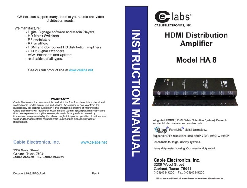
Cable Electronics CE Labs HDMI Distribution Amplifier HA 8 instruction manual

