520-259-000 6/00 Powerwise Models 4061, 4063 Page 10
PRINCIPLE OF PUMP OPERATION
This ball type check valve pump is
poweredbycompressedair andis a1:1
ratio design. The inner side of one
diaphragm chamber is alternately
pressurized while simultaneously
exhaustingtheotherinnerchamber.This
causes the diaphragms, which are
connected by a common rod secured
by plates to the centers of the
diaphragms,to move in a reciprocating
action.(As onediaphragm performsthe
discharge stroke the other diaphragm
is pulled to perform the suction stroke
in the opposite chamber.) Air pressure
is applied over the entire inner surface
of the diaphragm while liquid is
dischargedfromthe oppositeside ofthe
diaphragm.The diaphragm operates in
a balanced condition during the
dischargestrokewhich allowsthe pump
tobe operated atdischarge heads over
200feet (61 meters) of water.
For maximum diaphragm life, keep
the pump as close to the liquid being
pumped as possible. Positive suction
headinexcess of10 feetof liquid(3.048
meters) may require a back pressure
regulating device to maximize
diaphragmlife.
Alternate pressurizing and
exhausting of the diaphragm chamber
isperformed by an externallymounted,
pilot operated, four way spool type air
distributionvalve. Whenthe spoolshifts
to one end of the valve body, inlet
pressure is applied to one diaphragm
chamber and the other diaphragm
chamber exhausts. When the spool
shifts to the opposite end of the valve
body, the pressure to the chambers is
reversed.Theair distributionvalve spool
is moved by a internal pilot valve which
alternately pressurizes one end of the
air distribution valve spool while
exhaustingtheother end.The pilotvalve
is shifted at each end of the diaphragm
stroke when a actuator plunger is
contacted by the diaphragm plate. This
actuatorplunger thenpushesthe end of
the pilot valve spool into position to
activatethe air distributionvalve.
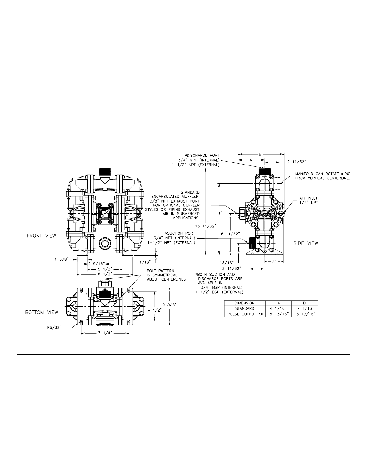
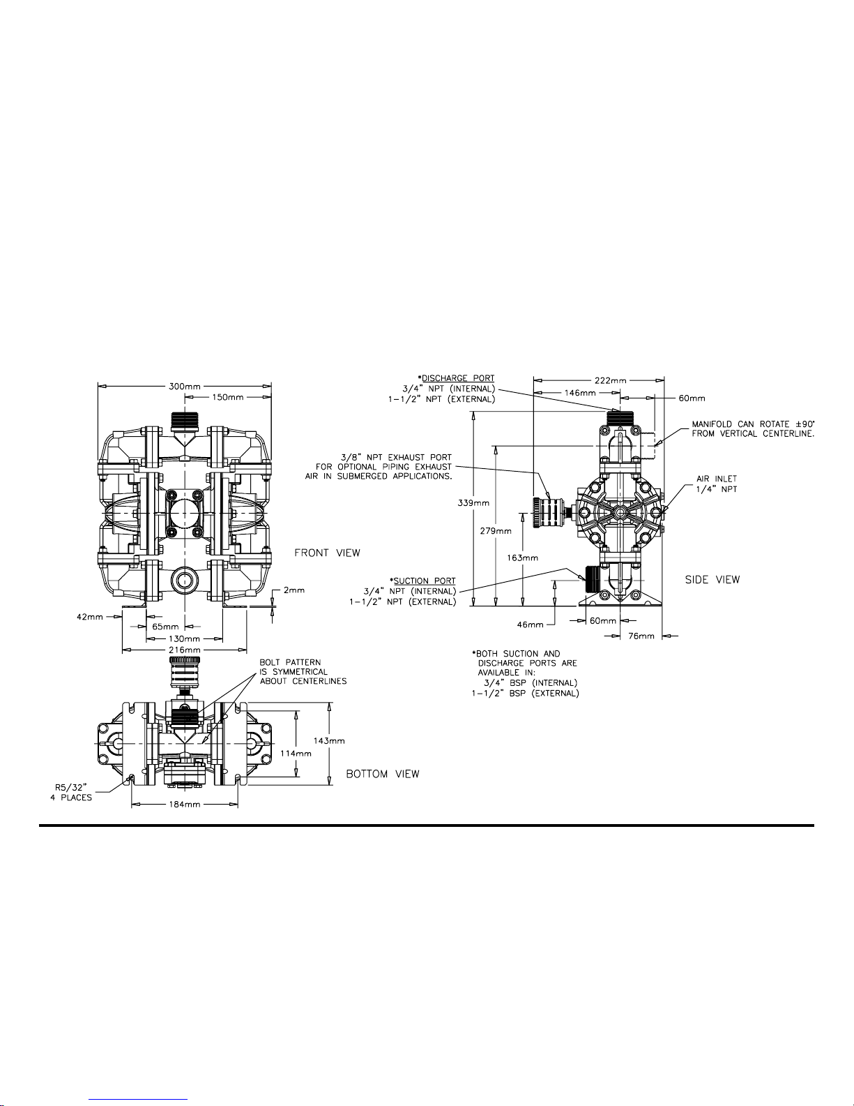
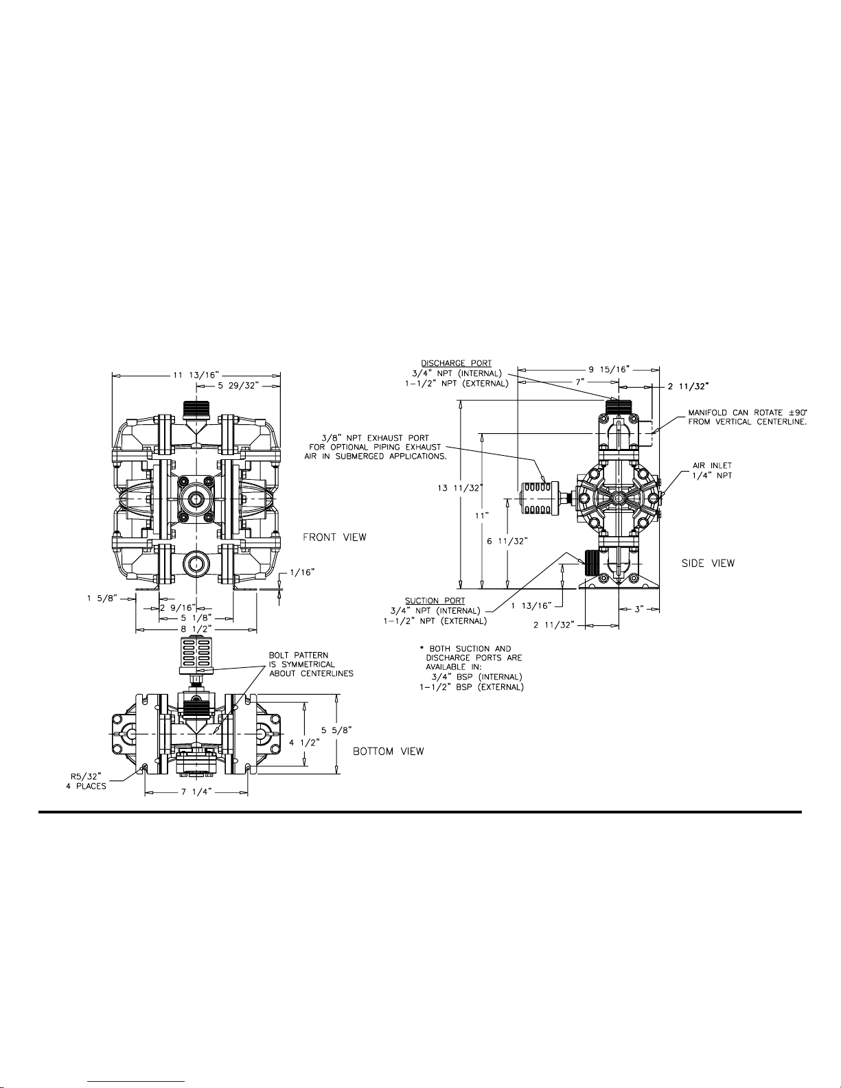
The chambers are connected with
manifolds with a suction and discharge
check valve for each chamber,
maintainingflowin onedirection through
thepump.
INSTALLATION AND START-UP
Locate the pump as close to the
productbeingpumpedaspossible.Keep
the suction line length and number of
fittingsto a minimum.Do not reduce the
suctionline diameter.
Forinstallations of rigid piping,short
sections of flexible hose should be
installed between the pump and the
piping. The flexible hose reduces
vibration and strain to the pumping
system. A surge suppressor is
recommended to further reduce
pulsationin flow.
AIR SUPPLY
Air supply pressure cannot exceed
100 psi (7 bar). Connect the pump air
inlettoan airsupply ofsufficient capacity
and pressure required for desired
performance. When the air supply line
is solid piping, use a short length of
flexible hose not less than ½" (13mm)
in diameter between the pump and the
pipingto reducestrain to thepiping. The
weight of the air supply line, regulators
and filters must be supported by some
meansotherthantheairinletcap.Failure
to provide support for the piping may
resultindamagetothe pump.Apressure
regulating valve should be installed to
insure air supply pressure does not
exceedrecommended limits.
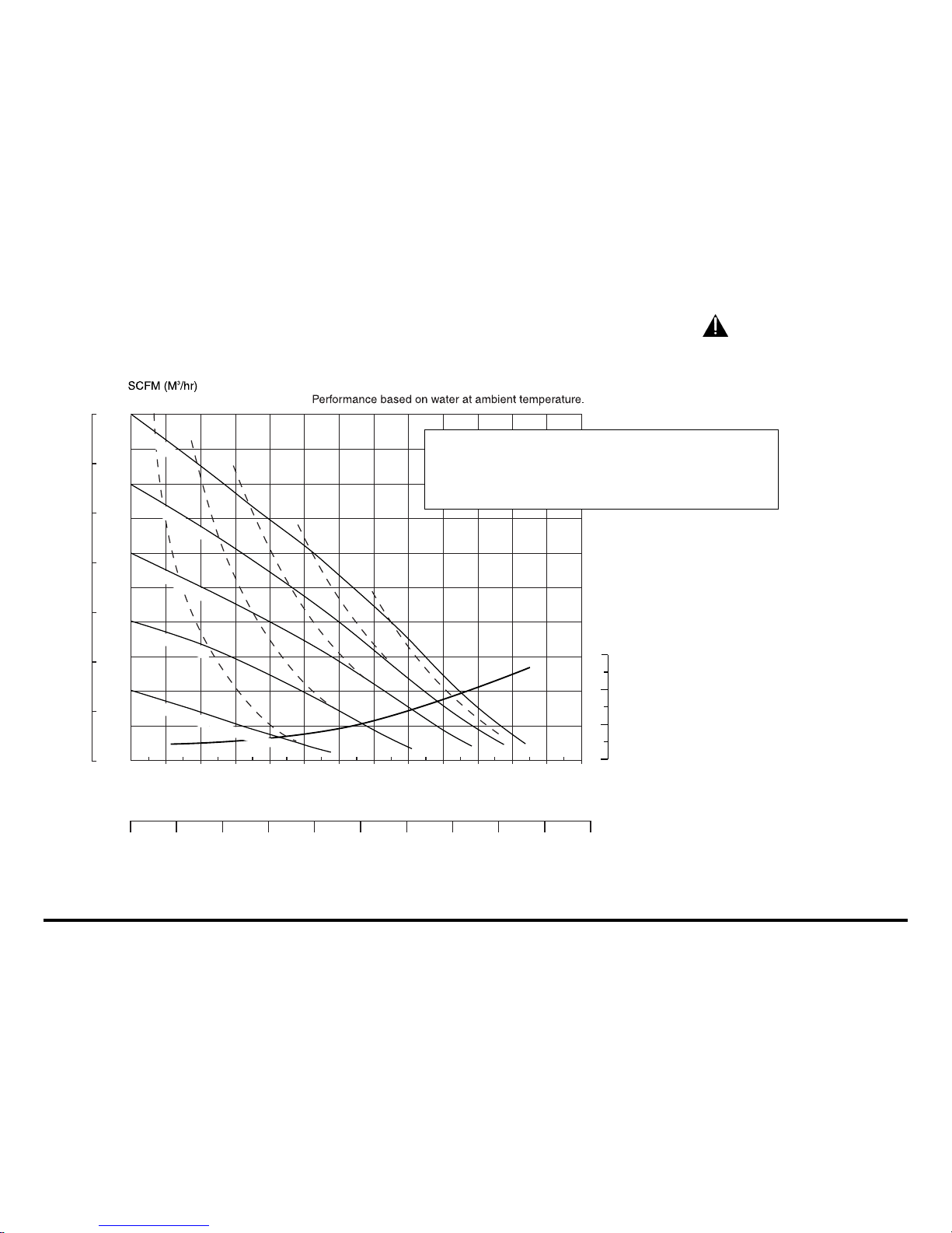
AIRVALVE LUBRICATION
Theairdistribution valveand thepilot
valvearedesignedtooperate WITHOUT
lubrication.Thisisthe preferredmode of
operation. There may be instances of
personal preference or poor quality air
supplies when lubrication of the
compressed air supply is required. The
pump air system will operate with
properly lubricated compressed air
supply. Proper lubrication requires the
useof an air line lubricatorsetto deliver
one drop of SAE 10 non-detergent oil
for every 20 SCFM (9.4 liters/sec.) of
air the pump consumes at the point of
operation.Consultthe pump’spublished
Performance Curve to determine this.
AIR LINE MOISTURE
Water in the compressed air supply
can create problems such as icing or
freezing of the exhaust air, causing the
pump to cycle erratically or stop
operating. Water in the air supply can
be reduced by using a point-of-use air
dryerto supplementthe user’sair drying
equipment. This device removes water
from the compressed air supply and
alleviatestheicingor freezingproblems.
AIR INLET AND PRIMING
To startthe pump, open theairvalve
approximately ½ to ¾ turn. After the
pumpprimes,theairvalvecanbeopened
toincreaseair flowasdesired.Ifopening
thevalveincreasescyclingrate,butdoes
not increase the rate of flow, cavitation
hasoccurred.Thevalveshouldbeclosed
slightly to obtain the most efficient air
flowto pump flow ratio.
BETWEEN USES
Whenthe pumpis used formaterials
that tend to settle out or solidify when
notinmotion,thepumpshouldbeflushed
after each use to prevent damage.
(Productremaininginthepumpbetween
uses could dry out or settle out. This
could cause problems with the
diaphragmsandcheck valvesatrestart.)
Infreezing temperaturesthe pumpmust
becompletely drained between uses in
all cases.