Powr-Kraft PK30255L User manual

2-Stage Snow Thrower
Operator’s Manual
MODEL NUMBER :o PK30255L o PK30265L
SERIAL NUMBER : ________________________
Both model number and serial number may be found on the main
label. You should record both of them in a safe place for future use.
FOR YOUR SAFETY
READ AND UNDERSTAND THE ENTIRE MANUAL BEFORE
OPERATING MACHINE
Save This Manual for Future Reference
Original Instruction
Before starting the engine,
check engine oil level and
ensure the engine is filled as
described in the Engine Manual.
2-STAGE SNOW THROWER
US
2
TABLE OF CONTENTS
Introduction
Environmental
Symbols
Safety
General Safety Rules
Specific Safety Rules
Contents supplied
Assembly
Know your machine
Features and Controls
Adjustments
Operation
Freewheeling and Self-Propelling
Starting and Stopping the engine
Snow Throwing Tips
Traveling
Transport
Maintenance
Engine
Lubrication
Battery
Off-Season Storage
Service
Belt Replacement
Friction Wheel Replacement
Charging Battery
Trouble Shooting
Parts Schedule
Part Order Form
Warranty & Registration
Extended Warranty
INTRODUCTION
Your new snow thrower will more than satisfy your
expectations. It has been manufactured under
stringent quality standards to meet superior
performance criteria. You will find it easy and safe
to operate, and with proper care, it will give you
many years of dependable service.
Carefully read through this entire
operator’s manual before using your new
snow thrower. Take special care to heed
the cautions and warnings.
Your snow thrower has many features that will
make your job faster and easier. Safety,
performance, and dependability have been given
to top priority in the development of this machine,
making it easy to maintain and operate.
The Engine manufacturer is responsible for all
engine-related issues with regards to performance,
power rating, specifications, warranty and service.
Please refer to the Engine Manufacturer’s
owner’s/operator’s manual, packed separately
with your unit, for more information.
Specifications
Item #
30250 30255 30260 30265 30270
30355 30360 30365 30370
Clearing Width 57cm 62cm 67cm 72cm 77cm
Intake Height 53.5cm
Auger Dia. 30.0cm
Impeller Dia. 30.0cm
Speed 6F+2R
ENVIRONMENTAL
Recycle unwanted materials instead
of disposing off them as waste. All
tools, hoses and packaging should be
resorted, taken to the local recycling
center and disposed off in an
environmentally safe way.
SYMBOLS
The rating plate on your machine may show
symbols. These represent important information
about the product or instructions on its use.
Read these instructions for use
carefully.
Wear eye protection.
Wear hearing protection.
Wear safety footwear.

2-STAGE SNOW THROWER 3
US
Revision 3-12-14
SAFETY
General Safety Rules
Understand your machine
Allow operation only by properly trained adult,
never children.
Read and understand the operator’s manual and
labels affixed to the machine. Learn its application
and limitations as well as the specific potential
hazards peculiar to it.
Be thoroughly familiar with the controls and their
proper operation. Know how to stop the machine
and disengage the controls quickly.
Make sure to read and understand all the
instructions and safety precautions as outlined in
the Engine Manufacturer’s Manual, packed
separately with your unit. Do not attempt to
operate the machine until you fully understand
how to properly operate and maintain the Engine
and how to avoid accidental injuries and/or
property damage.
Work area
Never start or run the engine inside a closed area.
The exhaust fumes are dangerous, containing
carbon monoxide, an odorless and deadly gas.
Operate this unit only in a well ventilated outdoor
area.
Never operate the machine without good visibility
or light.
Never operate the machine on a steep slope.
Personal safety
Do not operate the machine while under the
influence of drugs, alcohol, or any medication that
could affect your ability to use it properly.
Dress properly. Wear heavy long pants, boots and
gloves. Do not wear loose clothing, short pants,
and jewelry of any kind. Secure long hair so it is
above shoulder level. Keep your hair, clothing and
gloves away from moving parts. Loose clothes,
jewelry or long hair can be caught in moving parts.
Use safety equipment. Always wear eye
protection. Safety equipment such as a dust mask,
hard hat, or hearing protection used for
appropriate conditions will reduce personal
injuries.
Keep bystanders away.
Stop engine and remove ignition
key prior to leaving the operator’s
position.
Only use clean-out tool to clear
blockage. Never use your hands.
It is forbidden to remove or tamper
with the protection devices and
safety devices.
Do not smoke or have open flames.
Do not touch a hot muffler, gear
housing or cylinder.
Stop engine, remove key, read
manual before making any repairs
or adjustments.
Keep hands out of the inlet and
discharge openings while machine
is running.
Stay away from rotating augers.
Never direct discharge towards
persons or property.

2-STAGE SNOW THROWER
US
4
Check your machine before starting it. Keep
guards in place and in working order. Make sure
all nuts, bolts, etc. are securely tightened.
Disengage all clutches and shift into neutral before
starting the engine.
Never operate the machine when it is in need of
repair or is in poor mechanical condition. Replace
damaged, missing or failed parts before using it.
Check for fuel leaks. Keep the machine in safe
working condition.
Never tamper with safety device. Check their
proper operation regularly.
Do not use the machine if the engine’s throttle
control does not turn it on or off. Any gasoline
powered machine that can not be controlled with
the engine throttle control is dangerous and must
be replaced.
Form a habit of checking to see that keys and
adjusting wrenches are removed from machine
area before starting it. A wrench or a key that is left
attached to a rotating part of the machine may
result in personal injury.
Stay alert, watch what you are doing and use
common sense when operating the machine.
Do not overreach. Do not operate the machine
while barefoot or when wearing sandals or similar
lightweight footwear. Wear protective footwear
that will protect your feet and improve your footing
on slippery surfaces. Keep proper footing and
balance at all times. This enables better control of
the machine in unexpected situations.
Avoid accidental starting. Be sure the engine’s
throttle control is off before transporting the
machine or performing any maintenance or
service on the unit. Transporting or performing
maintenance or service on a machine with its
throttle control on invites accidents.
Fuel safety
Fuel is highly flammable, and its vapors can
explode if ignited. Take precautions when using to
reduce the chance of serious personal injury.
When refilling or draining the fuel tank, use an
approved fuel storage container while in a clean,
well-ventilated outdoor area. Do not smoke, or
allow sparks, open flames or other sources of
ignition near the area while adding fuel or
operating the unit. Never fill fuel tank indoors.
Keep grounded conductive objects, such as tools,
away from exposed, live electrical parts and
connections to avoid sparking or arcing. These
events could ignite fumes or vapors.
Always stop the engine and allow it to cool before
filling the fuel tank. Never remove the cap of the
fuel tank or add fuel while the engine is running or
when the engine is hot. Do not operate the
machine with known leaks in the fuel system.
When practical, remove the machine from the
truck or trailer and refuel it on the ground. If this is
not possible, then refuel the machine on a trailer
with a portable container, rather than from a fuel
dispenser nozzle.
Loose the fuel tank cap slowly to relieve any
pressure in the tank.
Keep the nozzle in contact with the firm of the fuel
tank or container opening at all times until fueling
is complete. Do not use a nozzle lock-open
device.
Never over fill fuel tank. Fill tank to no more than
12.5mm (1/2”) below the bottom of the filler neck
to provide space for expansion as the heat of the
engine and/or sun cause fuel to expand.
Replace all fuel tank and container caps securely

2-STAGE SNOW THROWER 5
US
Revision 3-12-14
and wipe up spilled fuel. Never operate the unit
without the fuel cap securely in place.
Avoid creating a source of ignition for spilled fuel.
If fuel is spilled, do not attempt to start the engine
but move the machine away from the area of
spillage and avoid creating any source of ignition
until fuel vapors have dissipated. Serious personal
injury can occur when fuel is pilled on yourself or
your clothes which can ignite. Wash your skin and
change clothes immediately.
Store fuel in containers specifically designed and
approved for this purpose.
Never fill containers inside a vehicle or on a truck
or trailer bed with a plastic liner. Always place
containers on the ground away from your vehicle
before filling.
Store fuel in a cool, well-ventilated area. Safely
away from sparks, open flames or other sources
of ignition.
Never store fuel or machine with fuel in the tank
inside a building where fumes may reach a spark,
open flame, or other sources of ignition, such as a
water heater, furnace, clothes dryer and the like.
Allow the engine to cool before storing in any
enclosure.
Machine use and care
Never pick up or carry a machine while the engine
is running.
Do not force the machine. Use the correct
machine for your application. The correct machine
will do the job better and safer at the rate for which
it was designed.
Do not change the engine governor settings or
over-speed the engine. The governor controls the
maximum safe operating speed of the engine.
Do not put hands or feet near rotating parts.
Avoid contact with hot fuel, oil, exhaust fumes and
hot surfaces. Do not touch the engine or muffler.
These parts get extremely hot from operation.
They remain hot for a short time after you turn off
the unit. Allow the engine to cool before doing
maintenance or making adjustments.
After striking a foreign object, stop the engine,
remove the wire from the spark plug, thoroughly
inspect the machine for any damage, and repair
the damage before restarting and operating the
machine.
If the machine should start to make an unusual
noise or vibration, immediately shut off the engine,
disconnect the spark plug wire, and check for the
cause. Unusual noise or vibration is generally
warning of trouble.
Use only attachments and accessories approved
by the manufacturer. Failure to do so can result in
personal injury.
Maintain the machine. Check for misalignment or
binding of moving parts, breakage of parts and
any other condition that may affect the machine’s
operation. If damaged, have the machine repaired
before use. Many accidents are caused by poorly
maintained equipment.
Keep the engine and muffler free of grass, leaves,
excessive grease or carbon build up to reduce the
chance of a fire hazard.
Never douse or squirt the unit with water or any
other liquid. Keep handles dry, clean and free from
debris. Clean after each use.
Observe proper disposal laws and regulations for
gas, oil, etc. to protect the environment.
Store idle machine out of the reach of children and
do not allow persons unfamiliar with the machine

2-STAGE SNOW THROWER 6
US
Revision 3-12-14
or these instructions to operate it. Machine is
dangerous in the hands of untrained users.
Service
Before cleaning, repair, inspecting, or adjusting
shut off the engine and make certain all moving
parts have stopped. Always make sure the
engine’s throttle control is in its STOP position.
Disconnect the spark plug wire, and keep the wire
away from the plug to prevent accidental starting.
Have your machine serviced by qualified repair
personnel using only identical replacement parts.
This will ensure that the safety of the machine
maintained.
Specific Safety Rules
Do not operate without wearing adequate winter
outer garments.
Do not use the machine on a roof.
Do not run the engine indoors, except when
starting the engine and for transporting the snow
thrower in or out of the building. Open the outside
doors; exhaust fumes are dangerous.
Always check overhead and side clearances
carefully before operation. Always be aware of
traffic when operating along streets or curbs.
Thoroughly inspect the area to be worked. Keep
the working area clean and free of toys,
doormats, newspapers, sleds, boards, wires and
other foreign objects, which could be tripped over
or thrown by the auger. Check for weak spots on
docks, ramps or floors.
Plan your snow-throwing pattern to avoid
discharge toward people or areas where property
damage can occur.
Do not operate near drop-offs, ditches, or
embankments. Machine can suddenly turn over if
a wheel is over the edge of a cliff or ditch, or if an
edge caves in.
Keep all bystanders, children, and pets at least
23m (75 feet) away. If you are approached, stop
the unit immediately.
Use a grounded three-wire extension cord and
receptacle for all machines with electric start
engines.
Check clutch and brake operation frequently.
Adjust and service as required. All motion of drive
wheels and auger must stop quickly when control
levers are released.
Let engine and machine adjust to outdoor
temperature before starting to clear snow.
Stay alert for hidden hazards or traffic.
Do not overload machine capacity by attempting
to clear snow at too fast of a rate.
Do not throw snow any higher than necessary.
Adjust auger housing height to clear gravel or
crushed rock surfaces. Exercise extreme caution
when operating.
Exercise caution to avoid slipping or falling,
especially when operating in reverse. Never
operate machine at high transport speeds on
slippery surfaces. Always look down and behind
before and while backing.
Do not operate on steep slopes. Do not clear
snow across the face of slopes. Keep all
movement on slopes slow and gradual. Do not
make sudden changes in speed or direction. Use
a slow speed to avoid stops or shifts on slopes.
Avoid starting or stopping on a slope. Do not park
machine on a slope unless absolutely necessary.

2-STAGE SNOW THROWER 7
US
Revision 3-12-14
When parking on a slope, always block the
wheels.
Disengage power to the auger when transporting
or not in use.
Disengage all control levers and stop engine
before you leave the operating position (behind
the handles). Wait until the auger comes to a
complete stop before unclogging the chute
assembly, making any adjustments, or
inspections.
Hand contact with the rotating parts inside the
discharge chute is the most common cause of
injury associated with snow throwers. Do not
unclog chute assembly while engine is running.
Shut off engine and remain behind handles until
all moving parts have stopped before unclogging.
Never put your hand in the discharge or collector
openings. Always use the clean-out tool provided
to unclog the discharge opening.
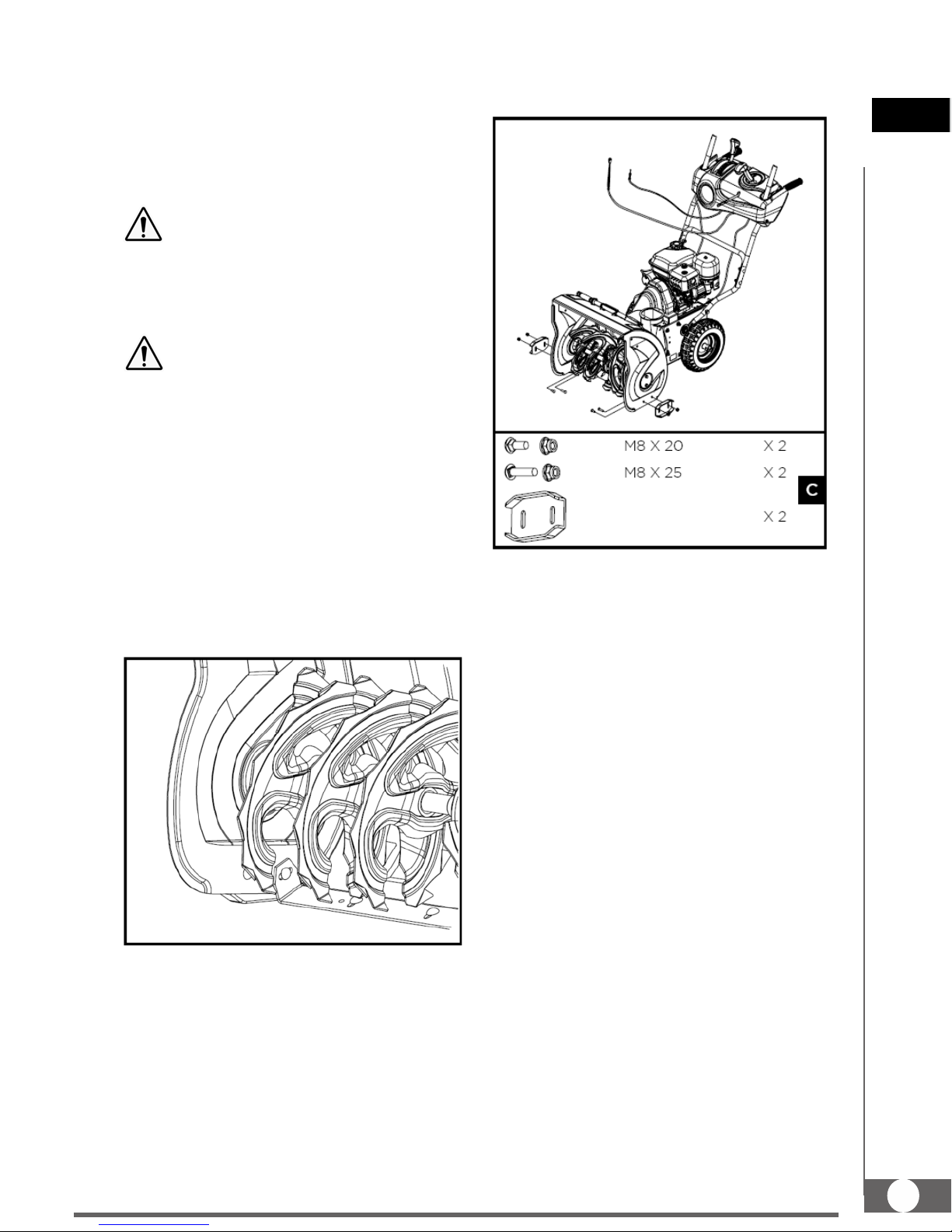
CONTENTS SUPPLIED
The snow thrower comes partially assembled and is shipped in carefully packed carton. After all the
parts have been removed from the carton, you should have:

2-STAGE SNOW THROWER
US
8
1. Snow Thrower Unit
2. Discharge Chute
3. Handlebars
4. Lower Handle
5. Long Chute Rod
6. Shift Rod
7. Operator’s Manual & Engine Manual
8. Engine Hardware Bag
9. Snow Thrower Hardware Bag, including
ASSEMBLY
Following the assembly directions below, you will
assemble the snow thrower in a few minutes
Handlebars
1. Position the lower handle against the left and
right sides of the machine. Align the holes in the
handle with the side plates and secure lower
handle with the screws and the washers until they
are finger tight.
2. Keep the lower handle level and tighten all four
screws.
3. Raise the handlebars into operation position
and secure the handlebars with M8X45 screws,
washers and nuts until they are finger tight.
4. Ensure that the handles are at the same height,
and then tighten the fasteners securely.
Tires
The tires are over-inflated at factory for shipping
purposes. Check the pressure in the tires.
Reduce or Increase equally in both tires to the
manufacturer’s recommended pressure.
Under any circumstance do not exceed
manufacturer’s recommended pressure.
Excessive pressure when seating beads
2-STAGE SNOW THROWER 9
US
Revision 3-12-14
may cause tire/rim assembly to burst with
force sufficient to cause serious injury.
Refer to side wall of tire for recommended
pressure.
Equal tire pressure should be maintained
at all times. If the tire pressure is not
equal in both tires, the machine may not
travel in a straight path and the scraper
blade may wear unevenly.
Keep tires free of gasoline and oil, which
can harm rubber.
Skid Shoes
1. Move the machine to a level surface.
2. Support the auger blades so that they are
3mm (1/8”) off the ground.
3. Check the scraper blade adjustment. The
scraper blade should be 3mm (1/8”) above
and parallel to a level ground. To adjust the
scraper blade, loosen the seven mounting
screws (two on each side), level the scraper
blade, and tighten the mounting screws.
4. Attach both skid shoes to the auger side
plates with the screws and nuts. Move the
skid shoes down as far as possible. Be sure
both skid shoes are adjusted evenly. Tighten
securely.
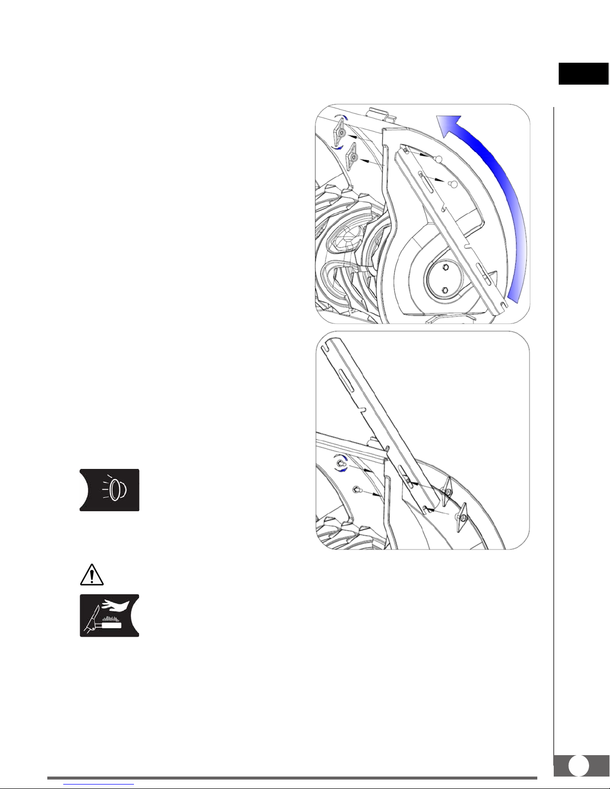
Discharge Chute
1. Grease underside of discharge chute ring (if
not already greased).
2. Install discharge chute over opening in the
auger housing. Orient the chute and pedestal
to its most vertical position and tighten
pedestal hardware.
3. Connect the deflector control cable eyelet to
the chute deflector as shown. Tighten
securely. Eyelet will be loose on shoulder bolt.
4. Insert the cable fitting into the cable bracket
on discharge chute.
5. Adjust and tighten jam nut.

2-STAGE SNOW THROWER
US
10
6. Remove the gear cover by removing the two
ST4.8X13 self-tapping screws.
7. Connect the chute lock cable to the lock latch
by fitting the cable ball end into the slot on the
lock latch and then insert the chute lock cable
fitting into the bracket on the chute pedestal.
8. Adjust and tighten jam nuts on cable fitting to
remove cable slack. Be sure not to pretension
lock latch so it retracts from the gear teeth.
9. Release the lock latch on the gear assembly
and turn the discharge chute straight ahead.
10. To ensure the discharge chute and chute
deflector follow their full range of travels,
make sure the joystick is in the center
position.
11. Slide chute rod without a pin through the
pedestal bracket and into hex hole in gear
assembly.
12. Secure the chute rod to the gear assembly
with a cotter pin and a washer.
13. Align the flattened back end of the long chute
rod with the flattened front end of the short
rod that extends from the control panel so that
they nest together.
14. Align the holes in the nested ends of the rods
and insert two M6X20 carriage bolts with
locknuts.

2-STAGE SNOW THROWER 11
US
Revision 3-12-14
15. Hold the trigger cap down and rotate the
joystick in a circle to ensure the that the
discharge chute and chute deflector operate
smoothly.
16. Install and secure the gear cover.
Speed Shift Linkage
1. Place the shift arm on shift yoke. Line up the
holes in the shift arm and shift yoke. Insert a
roll pin through the holes.
2. After the shift rod with a flat washer has been
inserted through the hole in the shift arm, add
the other flat washer on the shift rod, and
secure with a clevis pin.
3. Lift up on the shift rod. Loose the jam nut
under the trunnion and thread the trunnion
along the shift rod until it fits into the hole in
the shift lever. Tighten the jam nut and Install
washer and M8 nut. Tighten securely.

2-STAGE SNOW THROWER 12
US
Revision 3-12-14
Replacement Shear Pins
A pair of replacement auger shear pins and clevis
pins are included with your snow thrower. Store
them in a safe place until needed.
Spare Roll Pins
The impeller is secured to the impeller shaft with
roll pins.
Two 6x37 roll pins for impeller are supplied as
spare in the hardware bag. Store them in a safe
place until needed.
Battery (if so equipped)
1. Remove the battery cover by loosening the
screw and nut.
2. Connect positive (red) battery cable to the
battery terminal first, then negative (black)
battery cable. Check that all cable connectors
are tight.
3. Install battery cover and tighten the screw and
nut.
2-STAGE SNOW THROWER 13
US
Revision 3-12-14
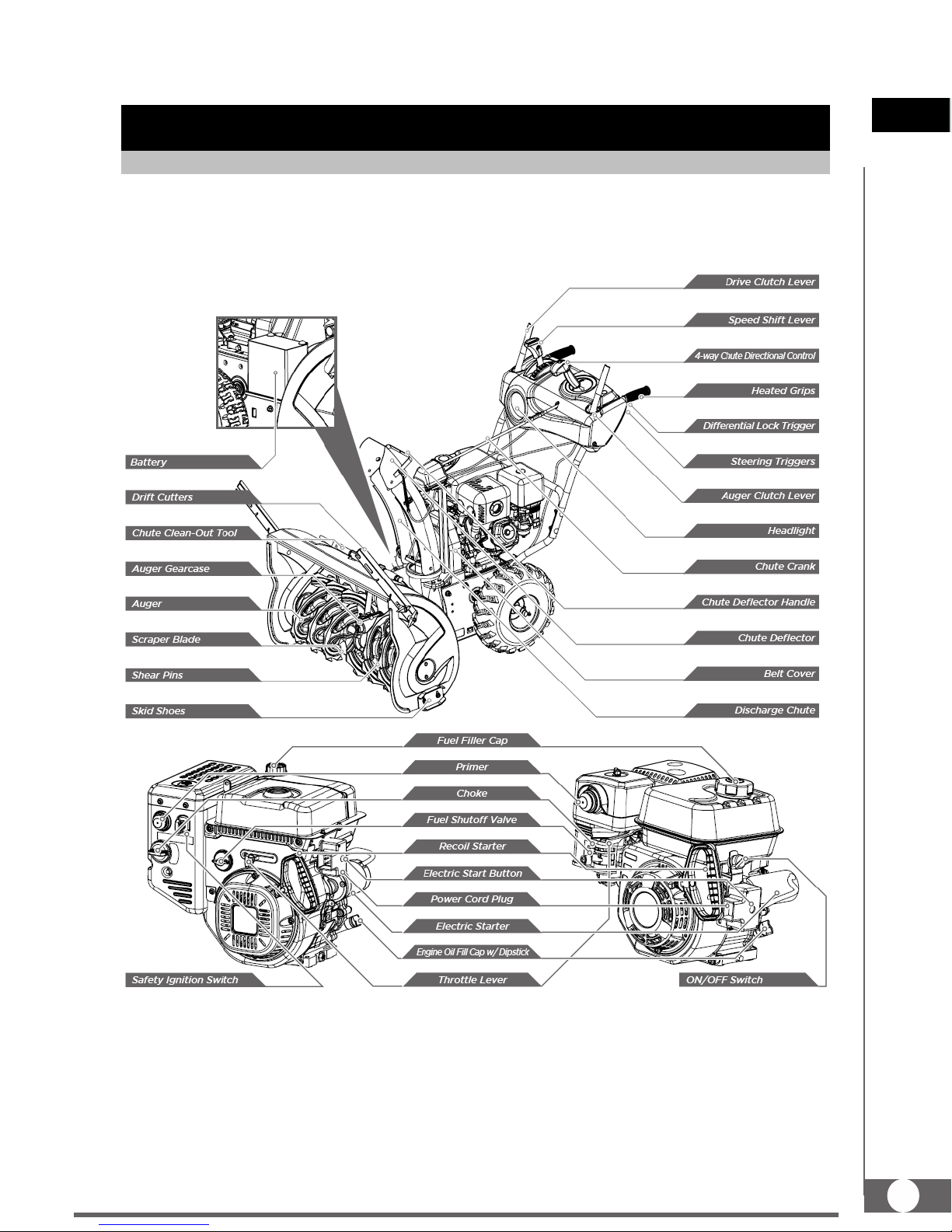
KNOW YOUR MACHINE
Features and Controls

2-STAGE SNOW THROWER
US
14
2-STAGE SNOW THROWER 15
US
Revision 3-12-14
Speed Shift Lever
The speed shift lever has 8 positions: 6 forward
speeds and 2 reverse. To change speeds, move
the speed shift lever to the desired position. The
lever locks in a notch at each speed selection.
Always release the drive clutch lever
before changing speeds. Failure to do so
will result in damage to the snow thrower.
Slower speeds are for heavier snow and faster
speeds are for light snow and transporting the
snow thrower. It is recommended that you use a
slower speed until you are familiar with the
operation of the snow thrower.
If the engine slows down under a load or
the wheels slip, shift the machine into a
lower gear.
If the front of the machine rides up, shift the
machine into a lower gear. If the front
continues to ride up, lift up on the handles.
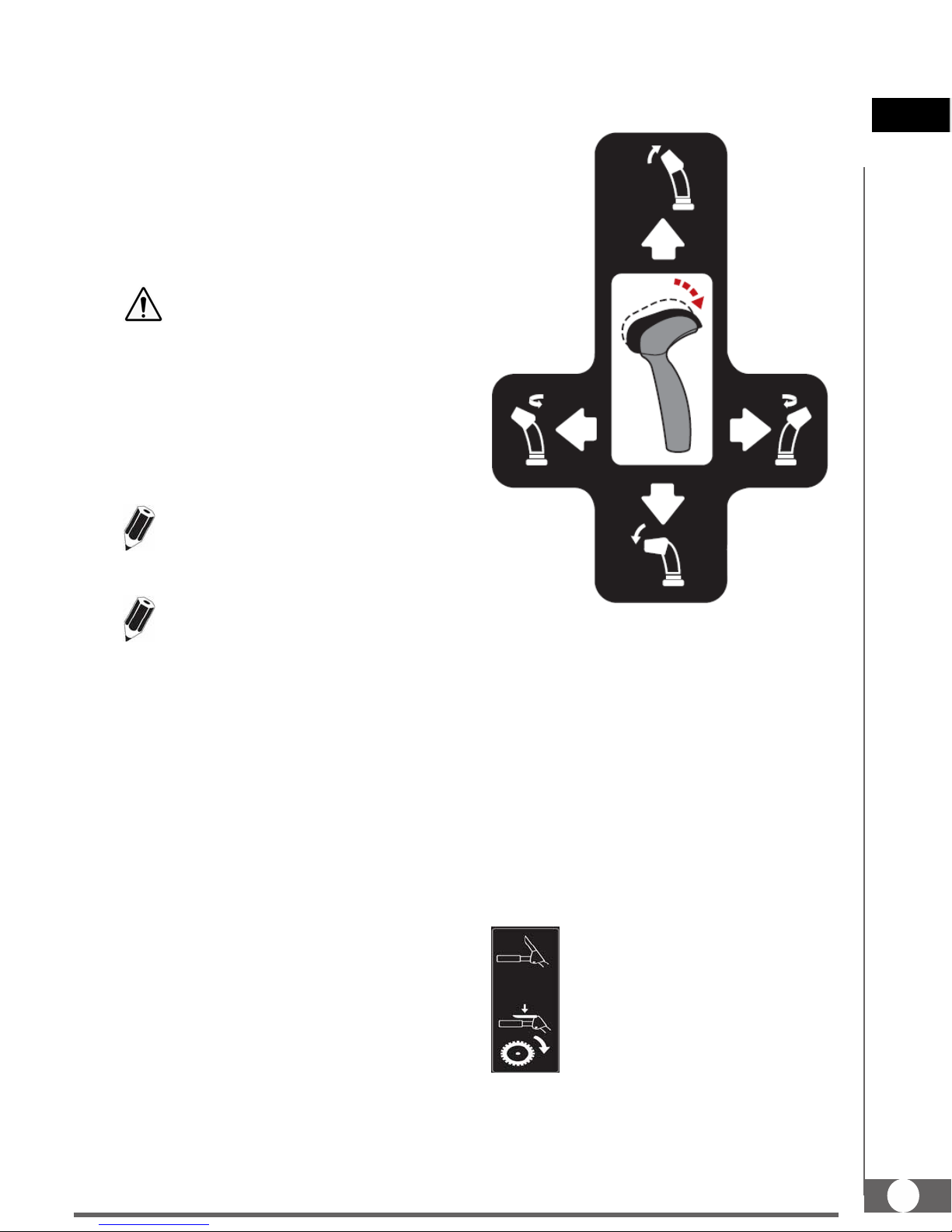
4-Way Chute Directional Control
Hold the trigger cap down to use the joystick to
move the discharge chute and the chute deflector.
Release the trigger cap to lock the discharge
chute and chute deflector into position.
To change the chute position, hold the trigger cap
down on the joystick and pivot the joystick to the
right or to the left.
To change the angle/distance which snow is
thrown, hold the trigger cap down on the joystick
and pivot the joy-stick forward or backward.
Drive Clutch Lever
Squeeze the clutch lever against the
handgrip to engage the wheel drive.
Release to disengage.

2-STAGE SNOW THROWER
US
16
Always release the drive clutch lever
before changing speeds. Failure to do so
will result in damage to the snow thrower.
Auger Clutch Lever
Squeeze the clutch lever against the
handgrip to engage the auger and
start snow throwing action. Release
to disengage.
When both auger clutch lever and drive clutch
lever are engaged, the auger clutch lever will lock
the drive clutch lever in the engaged position.
This allows you to release your right hand from
the handle and adjust the discharge chute
direction without interrupting the snow throwing
process.
Scraper Blade & Skid Shoes
The scraper blade allows better contact with the
surface being cleared. It also prevents damage to
the housing from normal use.
The skid shoes are located on each side of the
auger housing and control the distance between
the scraper blade and the ground. Adjust skid
shoes equally to keep the scraper blade level with
the ground.
The scraper blade & skid shoes are subject to
wear and damage. Both scraper blade and skid
shoes are adjustable to compensate for wear.
They should be checked and adjusted periodically.
Replace when necessary.
Damage to auger housing will result if
scraper blade wears down too far.
Both scraper blade and skid shoes have two wear
edges. When one side wears out, they can be
rotated 180oto use the other edge.
Shear Pins
The augers are secured to the auger shaft with
shear pins and clevis pins. If the auger should
strike a foreign object or ice jam, the snow
thrower is designed so that the pins may shear,
preventing damage to any other components. If
augers will not turn, check to see if the pins have
sheared. Replace the shear pins if necessary.
Do not substitute. Use only original
equipment shear pins as supplied with
your snow thrower.
Auger
When engaged, the augers rotate and draw snow
into the auger housing.
Discharge Chute
Snow drawn into the auger housing is discharged
out the discharge chute.
Chute Clean-Out Tool
Never use your hands to clear a clogged
discharge chute . Shut off engine and
remain behind handles until all moving
parts have stopped before unclogging.
2-STAGE SNOW THROWER 17
US
Revision 3-12-14
The chute clean-out tool is conveniently fastened
to the rear of the auger housing with a mounting
clip. Should snow and ice become lodged in the
discharge chute during operation, proceed as
follows to safely clean the discharge chute and
chute opening:
1. Release the auger clutch lever and shut off
the engine.
2. Remove the clean-out tool from the clip which
secures it to the rear of the auger housing.
3. Grasp the tool firmly by the handle and push
and twist the tool into the discharge chute to
dislodge the blockage.
4. Refasten the clean-out tool to the mounting
clip on the rear of the auger housing
5. Make sure the discharge chute is pointed in a
safe direction (no vehicles, buildings, people,
or other objects are in the direction of
discharge). Restart the engine. While
standing in the operator’s position (behind the
snow thrower), engage the auger control for a
few seconds to clear any remaining snow and
ice from the auger housing and the discharge
chute.
Headlight (if so equipped)
The headlight provides added
safety in low-visibility conditions.
Turn the headlight switch to the
ON position to activate.
Heated Grips (if so equipped)
It is recommended that you wear gloves
when using the heated grip. If the heated
grip becomes too hot, turn it off.
To activate the heated grips,
move the switch into ON
position.
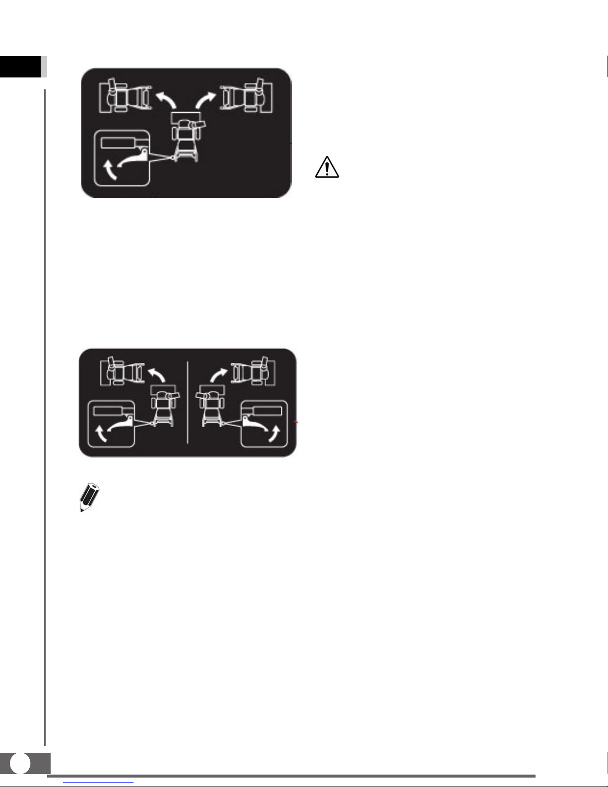
Drift Cutters (if so equipped)
Drift Cutters break up snow drifts that are taller
than the auger housing and direct the snow into
the auger. Store the drift cutters on the auger
housing when not in use. Reposition drift cutters
so they face forward as shown. Wing nuts should
be fastened on the outside of the auger housing.
Differential Lock Trigger (if so equipped)
The differential is locked for maximum traction.
With the differential locked, power is applied
equally to both wheels/tracks.
The differential lock trigger is located on the
underside of the left handle. Squeeze the trigger
to release the differential lock for easier turning.
2-STAGE SNOW THROWER
US
18
Steering Triggers (if so equipped)
Steering triggers are used to assist in steering the
snow thrower. The triggers are located on the
underside of each handlebar. When a trigger is
squeezed, it disengages the drive wheel on that
side and allows the snow thrower to turn in that
direction. With the drive clutch engaged, squeeze
the right trigger to turn right and squeeze the left
trigger to turn left.
It is easier to maneuver a non-running
snow thrower with both triggers held in
simultaneously.
Fuel Shutoff Valve
Always operate the snow thrower with the fuel
shut-off valve in the OPEN position. Close the
valve when you do not use the machine.
Throttle Lever
Move the throttle lever to the right to increase the
engine speed; move it to the left to decrease the
engine speed. Move the throttle lever to the
STOP position to stop the engine.
Choke
Engage choke by rotating lever to FULL position
whenever you are starting a cold engine. As
engine warms up, gradually rotate the choke to
the OFF position.
Do not use choke to start a warm engine.
.
Never use choke to stop engine.
Primer
Press the primer to pump additional fuel from the
carburetor to the cylinder for improved cold
weather starting.
Recoil Starter
The recoil starter is on the back side of the engine.
Pull the recoil starter handle to start the engine.
Safety Ignition Switch (if so equipped)
Insert the safety ignition key for engine to start
and run. To stop the engine, remove the key.
ON/OFF switch (if so equipped)
Used to STOP the engine. Move switch to OFF
position to stop engine. Place switch in ON
position for engine to start and run.
Ignition Switch (12V DC electric start)
The ignition switch is operated by a removable
key which has 3 positions of STOP, RUN and
START.
Electric Starter & Start Button (if so equipped)
The electric starter will start a properly choked
and cranked engine when the key is turned (12V
DC) or start button (120V or 230V AC) is pushed.
To start the machine, connect the electric starter
to an electric power source with an approved
extension cord and press the start button.

2-STAGE SNOW THROWER 19
US
Revision 3-12-14
Thoroughly inspect the electrical cord
before using the machine. If the cord is
damaged, do not operate the machine.
Replace or repair the damaged cord
immediately.
Connect extension cord to the electric
starter plug-in first and then to a power
outlet; disconnect the extension cord from
the power outlet first and then from the
machine.
To prevent damaging the electric starter,
do not run it more than 5 continuous
seconds each time you try to start. Wait
10 seconds between each attempt.
Track Lock Lever (if so equipped)
The track lock lever is used to select the position
of the auger housing and the method of track
operation. Move the lever to the right then forward
or backward to one of the three positions.
---------------- Transport
---------------- Normal
---------------- Deep Cutting
Transport – Raises the front end of the snow
thrower for easy transport. Using proper caution,
this position may also be used on many gravel
driveways to clear snow while leaving gravel
undisturbed.
Normal – Allows the tracks to be suspended
independently for continuous ground contact.
Deep Cutting – Locks the front end of the snow
thrower down to the ground for had-packed or icy
snow conditions.
Adjustments
Skid Shoes
Position the skid shoes based on surface
conditions. For removal of snow in normal
conditions, such as a paved driveway or sidewalk,
place skid shoes in the higher position to give a
3mm (1/8”) clearance between the scraper blade
and the ground. Use a middle or lower position
when the area to be cleared is uneven, such as a
gravel driveway.
It is not recommended to operate the
snow thrower on gravel as it can easily
pick up and throw by the impeller, causing
personal injury or damage to the snow
thrower and surrounding property.
If you choose to operate the snow thrower on a
gravel surface, use extra caution and keep the
skid shoes in position for maximum clearance
between the ground and the scraper blade.
Always adjust skid shoes after adjusting
scraper blade to prevent premature wear
to scraper blade or damage to auger
housing.
To adjust the skid shoes:
1. Loosen the four hex nuts (two on each side)
and carriage bolts. Move skid shoes to
desired position.

2-STAGE SNOW THROWER
US
20
2. Make sure the entire bottom surface of skid
shoe is against the ground to avoid uneven
wear on the skid shoes.
3. Retighten nuts and bolts securely.
Auger Clutch and Drive Clutch
When the auger clutch lever or drive clutch is
released and in the disengaged position, the
cable should have very little slack. It should bolt
be tight.
Auger must stop within 5 seconds when the auger
clutch lever is released. If auger clutch does not
engage or disengage properly, adjust auger
clutch before operation.
If the snow thrower’s drive is disengaging
intermittently during operation, or it drives when
you release the drive clutch lever, adjust the drive
clutch before operation.
Both auger clutch and drive clutch can be
adjusted at either end of their control cables.
1. Loosen adjusting nuts on cable support
bracket.
2. Slide the control cable up or down by
threading adjusting nuts to increase cable
tension or provide more slack.
3. Tighten nuts after proper adjustment is
achieved.
Chute Lock Latch
If the discharge chute does not lock into the
desired position or does not unlock so that chute
rotates freely, adjust the chute lock latch.
If the chute does not lock:
Loosen the cable by loosening the rearward
adjustment nut, and tightening the forward
adjustment nut against the bracket until the lock
latch fully engages the gear teeth.
If the chute does not unlock:
Tighten the cable by loosening the forward
adjustment nut, and then tightening the rear
adjustment nut against the bracket until all cable
slack is removed.
This manual suits for next models
1
Table of contents
Other Powr-Kraft Snow Blower manuals


