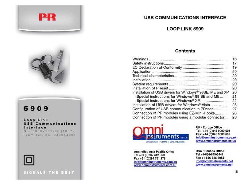
PR electronics Loop Link 5909 User manual

Programmable displays with a wide se-
lection of inputs and outputs for display of temperature,
volume and weight, etc. Feature linearisation, scaling,
and difference measurement functions for programming
via PReset software.
Interfaces for analogue and digital
signals as well as HART®signals between sensors / I/P
converters / frequency signals and control systems in Ex
zone 0, 1 & 2 and for some modules in zone 20, 21 & 22.
Galvanic isolators for analogue and digital
signals as well as HART®signals. A wide product range
with both loop-powered and universal isolators featuring
linearisation, inversion, and scaling of output signals.
PC or front programmable modules with
universal options for input, output and supply. This range
offers a number of advanced features such as process
calibration, linearisation and auto-diagnosis.
A wide selection of transmitters for DIN
form B mounting and DIN rail modules with analogue
and digital bus communication ranging from application-
specific to universal transmitters.
Displays
Temperature
Isolation
Ex barriers
Universal
DK
UK
FR
DE
Side 1
Page 15
Page 29
Seite 43
SIGNALS THE BEST
5909
Loop Link
USB Communications
Interface
No. 5909V101-IN (0722)
From ser. no. 040654001

USB-KOMMUNIKATIONSINTERFACE
LOOP LINK 5909
Indholdsfortegnelse
Advarsler ............................................................................ 2
Sikkerhedsregler................................................................. 3
EF-overensstemmelseserklæring....................................... 5
Anvendelse......................................................................... 6
Teknisk karakteristik ........................................................... 6
Installation .......................................................................... 6
Systemkrav......................................................................... 6
Installation af PReset ......................................................... 6
Installation af USB-drivere til Windows®98SE, ME og XP . 6
Specielt for Windows®98SE og ME.............................. 7
Specielt for Windows®XP.............................................. 8
Installation af USB-drivere til Windows®Vista .................... 9
Konfigurering af USB-kommunikation i PReset................. 13
Forbindelse af PR-moduler ved EZ-Mini-Hook tilslutning . 14
Forbindelse af PR-moduler ved modular stiktilslutning..... 14
1

SIKKERHEDSREGLER
DEFINITIONER:
Farlige spændinger er defineret som områderne:
75...1500 Volt DC og 50...1000 Volt AC.
Teknikere er kvalificerede personer, som er uddannet eller oplært til at kunne
udføre installation, betjening eller evt. fejlfinding både teknisk og sikkerheds-
mæssigt forsvarligt.
Operatører er personer, som under normal drift skal indstille og betjene
produktets trykknapper eller potentiometre, og som er gjort bekendt med ind-
holdet af denne manual.
MODTAGELSE OG UDPAKNING:
Udpak modulet uden at beskadige dette, og sørg for, at manualen altid følger
modulet og er tilgængelig.
Kontrollér ved modtagelsen, at modultypen svarer til den bestilte.
MILJØFORHOLD:
Undgå direkte sollys, kraftigt støv eller varme, mekaniske rystelser og stød, og
udsæt ikke modulet for regn eller kraftig fugt. Om nødvendigt skal opvarmning,
udover de opgivne grænser for omgivelsestemperatur, forhindres ved hjælp af
ventilation.
Alle moduler hører til Installationskategori II, Forureningsgrad 1 og Isolations-
klasse II.
INSTALLATION:
Modulet må kun tilsluttes af teknikere, som er bekendte med de tekniske ud-
tryk, advarsler og instruktioner i manualen, og som vil følge disse.
Hvis der er tvivl om modulets rette håndtering, skal der rettes henvendelse til
den lokale forhandler eller alternativt direkte til:
PR electronics A/S, Lerbakken 10, DK-8410 Rønde tlf: +45 86 37 26 77.
32
ADVARSEL
Dette modul kan ved tilslutning til SYSTEM 5000 gennem kom-
munikationskablet få forbindelse til livsfarlige elektriske spæn-
dinger. Hvis denne advarsel ignoreres, kan det føre til alvorlig
legemsbeskadigelse eller mekanisk ødelæggelse.
For at undgå faren for elektriske stød og brand, skal manualens
sikkerhedsregler overholdes, og vejledningerne skal følges.
Modulet må kun benyttes som beskrevet i det følgende.
Manualen skal studeres omhyggeligt, før modulet tages i brug.
Kun kvalificeret personale (teknikere) må benytte dette modul.
Hvis modulet ikke anvendes som beskrevet i denne manual, for-
ringes modulets beskyttelsesforanstaltninger.
ADVARSEL
Følgende operationer må kun udføres på modulet, når kommu-
nikationskablerne er uden forbindelse til SYSTEM 5000 og PC:
Fejlfinding på modulet.
Reparation af modulet må kun foretages af PR electronics A/S.
FARLIG
SPÆNDING
ADVARSEL
Kommunikationshunstikket i SYSTEM 5000 har forbindelse til
indgangsklemmer, hvor der kan forekomme farlige spændinger.
Det må kun tilsluttes programmeringsenheden 5909 via det
fastmonterede kommunikationskabel.
INSTAL-
LATION
SIGNATURFORKLARING:
Trekant med udråbstegn: Advarsel / krav. Hændelser der kan
føre til livstruende situationer.
CE-mærket er det synlige tegn på modulets overensstemmelse
med EU direktivernes krav.
Dobbelt isolation er symbolet for, at modulet overholder ekstra
krav til isolation.
GENERELT

5
PROGRAMMERING:
Under programmering skal måling og tilslutning af eksterne spændinger udføres
i henhold til denne manual, og manualen for den enhed som skal program-
meres, og teknikeren skal benytte sikkerhedmæssigt korrekte værktøjer og
instrumenter.
BETJENING UNDER NORMAL DRIFT:
Operatører må kun indstille eller betjene modulerne, når disse er fast installeret
på forsvarlig måde i tavler el. lignende, så betjeningen ikke medfører fare for liv
eller materiel. Dvs., at der ikke er berøringsfare, og at modulet er placeret, så
det er let at betjene.
RENGØRING:
Modulet må, i spændingsløs tilstand, rengøres med en klud let fugtet med de-
stilleret vand.
ANSVAR:
I det omfang instruktionerne i denne manual ikke nøje er overholdt, vil kunden
ikke kunne rette noget krav, som ellers måtte eksistere i henhold til den indgå-
ede salgsaftale, mod PR electronics A/S.
4
EF-OVERENSSTEMMELSESERKLÆRING
Som producent erklærer
PR electronics A/S
Lerbakken 10
DK-8410 Rønde
hermed at følgende produkt:
Type: 5909
Navn: Loop Link
er i overensstemmelse med følgende direktiver og standarder:
EMC-direktivet 2004/108/EF og senere tilføjelser
EN 61326
For specifikation af det acceptable EMC-niveau henvises til modulets
elektriske specifikationer.
Lavspændingsdirektivet 2006/95/EF og senere tilføjelser
EN 61010-1
Rønde, 31. maj 2007 Peter Rasmussen
Producentens underskrift

7
Anvendelse:
Loop Link 5909 er et USB-kommunikationsinterface til opsætning og monito-
rering af PR electronics’ pc-programmerbare moduler. USB-kommunikationen
understøttes af Windows®-versionerne 98SE, ME, 2000, XP og Vista. De PR-
moduler, som findes i konfigurationsprogrammet PReset ver 5.0 eller højere,
kan benytte Loop Link 5909.
Teknisk karakteristik:
Pc program-cd’en PReset ver 5.0 eller højere indeholder nødvendige (usig-
nerede) USB-drivere. Loop Link 5909 forsynes fra pc’ens USB-port. Hvis man
ønsker at spare strøm på en bærbar pc, kan man tilslutte en eksternt forsynet
hub og montere 5909’s USB-stik i denne. Der er galvanisk isolation mellem
kommunikationsstikket til PR-moduler og USB-tilsluningen på pc’en.
Installation:
Systemkrav:
Windows®98SE, ME, 2000, XP og Vista med følgende anbefalinger:
Hukommelse: 16 MB
Skærmopløsning: 800 x 600
Harddiskplads: 12 MB
Installation af PReset:
USB-kommunikationsinterfacet Loop Link 5909 må ikke være tilsluttet pc’ens
USB-port, før PReset-programmet er installeret.
PReset installeres på din harddisk, og registreringsdatabasen opdateres med
alle nødvendige oplysninger om programmet. Der vil automatisk blive oprettet et
PReset-ikon på skrivebordet.
1. Sæt cd-rom’en i dit cd-rom-drev, dialogen ”InstallShield Wizard
PReset - INSTALLER” vises automatisk.
2. Når installationsprogrammet er startet, vises en vejledning på skær-
men, som hjælper dig gennem resten af installationen.
3. Hvis AutoRun er slået fra i Windows®98SE, ME, 2000, XP og Vista,
startes installationsprogrammet ”cd-drev:\PResetWin\setup.exe”
med [Kør] i menuen start.
Installation af USB-drivere til Windows®98SE, ME og XP
Installer USB-driverne, medens PReset cd’en sidder i pc’en, altså umiddelbart
efter PReset-installationen. Vær opmærksom på, at der skal installeres to USB-
drivere.
1. Tilslut Loop Link 5909 til pc’ens USB-port.
6
2. Efter kort tid vises guiden ”Ny hardware fundet”. Denne guide hjæl-
per dig gennem den første USB-driver installation.
3. Ved tryk på [Udfør] bliver den første USB-driver installeret.
4. Guiden starter igen og hjælper dig gennem den anden USB-driver
installation.
5. Ved tryk på [Udfør] er USB-driver installationen fuldført.
Specielt for Windows®98SE og ME:
1. Når Windows®98SE og ME søger efter driverne, kan følgende med-
delelse forventes:
2. Efter klik på OK fremkommer en dialog, hvor stien
”cd-rom-drev:\drivere” skal angives. Du kan bruge [Gennemse] eller
selv indtaste stien.
3. Resten af installationen følger vejledningen ”Installation of USB-dri-
vere til Windows®98SE, ME og XP”.

9
Specielt for Windows®XP:
1. Du skal vælge [Nej, ikke denne gang] til følgende dialog:
2. Du skal vælge [Fortsæt alligevel] til følgende dialog:
3. Resten af installationen følger vejledningen ”Windows®98SE, ME
og XP”.
8
Installation af USB-drivere til Windows®Vista
Installer USB-driverne, medens PReset cd’en sidder i pc’en, altså umiddelbart
efter PReset-installationen.
1. Tilslut Loop Link 5909 til pc’ens USB-port.
2. Efter kort tid vises guiden ”Ny hardware fundet”. Denne guide hjæl-
per dig gennem den første USB-driver installation.
3. Klik [Annuller] på følgende skærmbillede:
4. Klik [Annuller] på efterfølgende skærmbillede:

10 11
5. Klik [Luk] på efterfølgende skærmbillede:
6. Åben enhedshåndtering og højreklik på [Ukendt enhed]. Venstreklik
derefter på [Opdater driversoftware].
7. Klik [Søg på computeren efter driversoftware] på efterfølgende
skærmbillede:
8. På efterfølgende skærmbillede skal stien ”cd-rom-drev:\drivere”
angives. Du kan bruge [Gennemse] eller selv indtaste stien. Klik
derefter på [Næste].

12 13
Konfigurering af USB-kommunikation i PReset:
1. Start PReset-programmet og vælg [Funktioner] [Vælg COM-port], og
”Option” vinduet vises på skærmen.
2. Vælg ”Next 5909”. PReset vælger nu en COM-port, som sammen-
kædes med den USB-port, Loop Link er forbundet til.
3. Hvis du vil have Loop Link konfigureret til andre USB-porte, skal du
forbinde Loop Link til disse porte og installere USB-driverne for hver
port. De andre USB-porte bliver først sammenkædet med en COM-
port i PReset, når ”Next 5909” er valgt.
9. Klik [Installer driversoftware alligevel] på efterfølgende skærmbil-
lede:
10. Klik [Luk] på efterfølgende skærmbillede:

14 15
Forbindelse af PR-moduler ved EZ-Mini-Hook tilslutning
Forbindelse af PR-moduler ved modular stiktilslutning
PR 5331, 5333, 5334, 5335
1
2
*
*
PR 6331, 6333, 6334, 6335
FileProductInputOutputCommunicationLanguageOption08:30:00
PRetop5331
Date:2004-8-10
043201594
PRelectronics
AnaloginputAnalogoutput
Serialno:
Inputtype:Outputtype:4-20mA
Upscale
Sensorerror:
Pt100DIN/IEC
0.00-50.00C
3-wire
1.00sec
------
Inputrange:
Connection:
Coldjunctioncomp:
Responsetime:
Tagno:
(23)
(21)
Loop
Link
13
11
Afbryd
+Vforsyning
* Kun forbundet ved
on-line programmering
Sort
Rød Gul
Grøn
Indgang
Modtagende
udstyr
Stikfor-
bindelse
USB-kabel
PR 5114, 5115, 5116, 5131
FileProductInputOutputCommunicationLanguageOption08:30:00
PRetop5331
Date:2004-8-10
043201594
PRelectronics
AnaloginputAnalogoutput
Serialno:
Inputtype:Outputtype:4-20mA
Upscale
Sensorerror:
Pt100DIN/IEC
0.00-50.00C
3-wire
1.00sec
------
Inputrange:
Connection:
Coldjunctioncomp:
Responsetime:
Tagno:
Loop
Link
USB-kabel
Programmeringskabel
med modularstik
USB COMMUNICATIONS INTERFACE
LOOP LINK 5909
Contents
Warnings ............................................................................ 16
Safety instructions.............................................................. 17
EC Declaration of Conformity ............................................ 19
Application ......................................................................... 20
Technical characteristics.................................................... 20
Installation .......................................................................... 20
System requirements ......................................................... 20
Installation of PReset ......................................................... 20
Installation of USB drivers for Windows®98SE, ME and XP 20
Special instructions for Windows®98 SE and ME ........ 21
Special instructions for Windows®XP........................... 22
Installation of USB drivers for Windows®Vista ................. 23
Configuration of USB communication in PReset............... 27
Connection of PR modules using EZ-Mini-Hooks............. 28
Connection of PR modules using a modular connector.... 28
15

16 17
SAFETY INSTRUCTIONS
DEFINITIONS:
Hazardous voltages have been defined as the ranges: 75...1500 Volt DC, and
50...1000 Volt AC.
Technicians are qualified persons educated or trained to mount, operate, and
also trouble-shoot technically correct and in accordance with safety regulations.
Operators, being familiar with the contents of this manual, adjust and operate
the knobs or potentiometers during normal operation.
RECEIPT AND UNPACKING:
Unpack the module without damaging it and make sure that the manual always
follows the module and is always available. The packing should always follow
the module until this has been permanently mounted.
Check at the receipt of the module whether the type corresponds to the one
ordered.
ENVIRONMENT:
Avoid direct sunlight, dust, high temperatures, mechanical vibrations and shock,
as well as rain and heavy moisture. If necessary, heating in excess of the stated
limits for ambient temperatures should be avoided by way of ventilation.
All modules fall under Installation Category II, Pollution Degree 1, and Insulation
Class II.
MOUNTING:
Only technicians who are familiar with the technical terms, warnings, and
instructions in the manual and who are able to follow these should connect the
module.
Should there be any doubt as to the correct handling of the module, please
contact your local distributor or, alternatively,
PR electronics A/S, Lerbakken 10, DK-8410 Rønde tlf: +45 86 37 26 77
1716
WARNING
When connected to SYSTEM 5000 by the communication cable,
this module can get connected to hazardous electric voltages.
Ignoring this warning can result in severe personal injury or me-
chanical damage.
To avoid the risk of electric shock and fire, the safety
instructions of this manual must be observed and the guidelines
followed.
The module must only be applied as described in the following.
Prior to the commissioning of the module, this manual must be
examined carefully.
Only qualified personnel (technicians) should use this module.
If the module is used in a manner not specified by the manufac-
turer, the protection provided by the module may be impaired.
WARNING
The following operations must only be carried out on a module
that is not connected to SYSTEM 5000 and a PC:
Troubleshooting the module.
Repair of the module must be done by PR electronics A/S only.
HAZARD-
OUS
VOLTAGE
WARNING
The female communication connector of SYSTEM 5000 is con-
nected to the input terminals on which dangerous voltages can
occur. It must only be connected to the programming unit 5909
by way of the attached communication cable.
INSTAL-
LATION
SYMBOL IDENTIFICATION:
Triangle with an exclamation mark: Warning/demand.
Potentially lethal situations.
The CE mark proves the compliance of the module with the re-
quirements of the EU directives.
The double insulation symbol shows that the module is
protected by double or reinforced insulation.
GENERAL

18 1919
PROGRAMMING:
During programming, the measuring and connection of external voltages must
be carried out according to the specifications of this manual and the manual for
the unit to be programmed.
The technician must use tools and instruments that are safe to use.
NORMAL OPERATION:
Operators are only allowed to adjust and operate modules that are safely fixed
in panels, etc., thus avoiding the danger of personal injury and damage. This
means there is no electrical shock hazard, and the module is easily accessible.
CLEANING:
When disconnected, the module may be cleaned with a cloth moistened with
distilled water.
LIABILITY:
To the extent that the instructions in this manual are not strictly observed, the
customer cannot advance a demand against PR electronics A/S that would
otherwise exist according to the concluded sales agreement.
18
EC DECLARATION OF CONFORMITY
As manufacturer
PR electronics A/S
Lerbakken 10
DK-8410 Rønde
hereby declares that the following product:
Type: 5909
Name: Loop Link
is in conformity with the following directives and standards:
EMC directive 2004/108//EC and later amendments
EN 61326
For specification of the acceptable EMC performance level, refer to the
electrical specifications for the module.
The Low Voltage Directive 2006/95/EC and later amendments
EN 61010-1
Rønde, 31 May 2007 Peter Rasmussen
Manufacturer’s signature

20 2121
Application:
Loop Link 5909 is a USB communications interface for configuration and moni-
toring of PR electronics’ PC-programmable modules. The USB communication
is supported by the Windows®versions 98SE, ME, 2000, XP and Vista. PR
modules available in the configuration program PReset ver. 5.0 or higher, can
be programmed by way of Loop Link 5909.
Technical characteristics:
The PC program CD PReset ver. 5.0 or higher contains the necessary (un-
signed) USB drivers. Loop Link 5909 is supplied from the USB port of the PC.
If you want to conserve power on a laptop, the USB connector of the 5909 can
be connected to an externally supplied hub. The communications connector on
the PR modules is galvanically isolated from the USB connection on the PC.
Installation:
System requirements:
Windows®98SE, ME, 2000, XP and Vista with the following recommendations:
Memory: 16 MB
Display resolution: 800 x 600
Hard disk space: 12 MB
Installation of PReset:
The USB communications interface Loop Link 5909 must not be connected to
the USB port of the PC until after installation of the PReset program.
PReset will be installed on your hard disk and the registry will be updated with
all necessary information on the program. A PReset icon will automatically be
placed on the desk top.
1. Insert the CD-ROM in the CD-ROM drive and the dialogue ”In-
stallShield Wizard PReset - INSTALL” will start automatically.
2. When the installation program has been started, on-screen guide-
lines will guide you through the rest of the installation.
3. If AutoRun is disabled in Windows®98SE, ME, 2000, XP and Vista,
click the ”Start” button, select [Run] and start the installation pro-
gram ”CD drive:\PResetWin\setup.exe”.
Installation of USB drivers for Windows®98SE, ME and XP
Install the USB drivers while the PReset CD is still in the drive, i.e. immediately
after the PReset installation. Please note that you need to install two USB dri-
vers.
20
1. Connect Loop Link 5909 to the USB port of the PC.
2. After a short while, the guide ”New hardware found” will be shown.
This guide will help you through the installation of the first USB dri-
ver.
3. When pressing [Execute] the first USB driver will be installed.
4. The guide starts again and helps you through the installation of the
second USB driver.
5. When pressing [Execute] the USB driver installation will be com-
plete.
Special instructions for Windows®98SE and ME:
1. When Windows®98SE and ME are searching for the drivers, the fol-
lowing message will probably appear:
2. After clicking OK, you will see the following dialogue where the path
”CD-ROM drive:\drivers” must be specified. Either use [Browse] or
type the path.
3. The installation will then continue according to the guidelines speci-
fied in ”Installation of USB drivers for Windows®98SE, ME and XP”.

22 23
Special instructions for Windows®XP:
1. You must say [No, not this time] to the following dialogue:
2. You must click [Continue anyway] in the following dialogue:
3. The installation will then continue according to the guidelines speci-
fied in ”Installation of USB drivers for Windows®98SE, ME and XP”.
22
Installation of USB drivers for Windows®Vista:
Install the USB drivers while the PReset CD is still in the drive, i.e. immediately
after the PReset installation.
1. Connect Loop Link 5909 to the USB port of the PC.
2. After a short while, the ”Found New Hardware Wizard” will be
shown. This guide will help you through the installation of the USB
driver.
3. Click [Cancel] in the following dialogue:
4. Click [Cancel] in the following dialogue:

24 25
5. Click [Close] in the following dialogue:
6. Open the Device Manager and right click [Unknown device]. Then
left click [Update Driver Software].
7. Click [Browse my computer for driver software] in the following
dialogue:
8. You will see the following dialogue where the path ”CD-ROM drive:\
Drivers” must be specified. Either use [Browse] or type the path.
Then click [Next]:

26 2727
Configuration of USB communication in PReset:
1. Start the PReset program and choose [Functions] [Set COM port],
and the ”Options” window is shown on screen.
2. Select ”Next 5909”. PReset now selects a COM port which will be
linked with the USB port to which Loop Link is connected.
3. If you want to configure Loop Link for other USB ports, you must
connect Loop Link to these ports and install the USB drivers for
each port. The other USB ports will not be linked with a COM port in
PReset until ”Next 5909” has been selected.
9. Click [Install this driver software anyway] in the following dialogue:
10. Click [Close] in the following dialogue:

28 29
Connection of PR modules using EZ-Mini-Hooks:
Connection of PR modules using a modular connector:
PR 5331, 5333, 5334, 5335
1
2
*
*
PR 6331, 6333, 6334, 6335
FileProductInputOutputCommunicationLanguageOption08:30:00
PRetop5331
Date:2004-8-10
043201594
PRelectronics
AnaloginputAnalogoutput
Serialno:
Inputtype:Outputtype:4-20mA
Upscale
Sensorerror:
Pt100DIN/IEC
0.00-50.00C
3-wire
1.00sec
------
Inputrange:
Connection:
Coldjunctioncomp:
Responsetime:
Tagno:
(23)
(21)
Loop
Link
13
11
Disconnect
+Vsupply
* Connected only for
on-line programming
Black
Red Yellow
Green
Input
Receiving
Equipment
Connector
USB cable
PR 5114, 5115, 5116, 5131
FileProductInputOutputCommunicationLanguageOption08:30:00
PRetop5331
Date:2004-8-10
043201594
PRelectronics
AnaloginputAnalogoutput
Serialno:
Inputtype:Outputtype:4-20mA
Upscale
Sensorerror:
Pt100DIN/IEC
0.00-50.00C
3-wire
1.00sec
------
Inputrange:
Connection:
Coldjunctioncomp:
Responsetime:
Tagno:
Loop
Link
USB cable
Programming cable
with modular connector
INTERFACE DE COMMUNICATION USB
LOOP LINK 5909
Sommaire
Avertissements................................................................... 30
Consignes de sécurité ....................................................... 31
Déclaration de conformité CE............................................ 33
Application ......................................................................... 34
Caractéristiques techniques .............................................. 34
Installation .......................................................................... 34
Exigences du système ....................................................... 34
Installation de PReset ........................................................ 34
Installation de pilotes USB pour
Windows®98SE, ME et XP................................................ 34
Instructions spécifiques à Windows®98SE et ME ........ 35
Instructions spécifiques à Windows®XP....................... 36
Installation de pilotes USB pour Windows®Vista ............. 37
Configuration de la communication USB dans PReset..... 41
Connexion des modules PR
à l’aide d’un câble EZ à pinces.......................................... 42
Connexion des modules PR
à l’aide d’un connecteur modulaire ................................... 42
29

30 31
CONSIGNES DE SECURITE
DEFINITIONS
Les gammes de tensions dangereuses sont les suivantes: de 75 à 1500 Vcc
et de 50 à 1000 Vca. Les techniciens sont des personnes qualifiées qui sont
capables de monter et de faire fonctionner un appareil, et d’y rechercher les
pannes, tout en respectant les règles de sécurité. Les opérateurs, connaissant
le contenu de ce guide, règlent et actionnent les boutons ou les potentiomètres
au cours des manipulations ordinaires.
RECEPTION ET DEBALLAGE
Déballez le module sans l’endommager. Le guide doit toujours être disponible
et se trouver à proximité du module. De même, il est recommandé de conserver
l’emballage du module tant que ce dernier n’est pas définitivement monté. A
la réception du module, vérifiez que le type de module reçu correspond à celui
que vous avez commandé.
ENVIRONNEMENT
N’exposez pas votre module aux rayons directs du soleil et choisissez un en-
droit à humidité modérée et à l’abri de la poussière, des températures élevées,
des chocs et des vibrations mécaniques et de la pluie. Le cas échéant, des
systèmes de ventilation permettent d’éviter qu’une pièce soit chauffée au-delà
des limites prescrites pour les températures ambiantes.
Tous les modules appartiennent à la catégorie d’installation Il, au degré de pol-
lution 1 et à la classe d’isolation Il.
MONTAGE
Il est conseillé de réserver le raccordement du module aux techniciens qui con-
naissent les termes techniques, les avertissements et les instructions de ce
guide et qui sont capables d’appliquer ces dernières.
Si vous avez un doute quelconque quant à la manipulation du module, veuillez
contacter votre distributeur local. Vous pouvez également vous adresser à
PR electronics SARL, Zac du Chêne, Activillage, 4, allée des Sorbiers, F-69673
Bron Cedex (tél. : (0) 472 140 607) ou à PR electronics A/S, Lerbakken 10, DK-
8410 Rønde, Danemark (tél.:+45 86 37 26 77).
3130
AVERTISSEMENT !
Loop Link 5909 peut à travers du câble de communication être
lié aux tensions dangereuses. Si vous ne tenez pas compte de
cet avertissement, cela peut causer des dommages corporels
ou des dégâts mécaniques.
Pour éviter les risques d’électrocution et d’incendie, conformez-
vous aux consignes de sécurité et suivez les instructions men-
tionnées dans ce guide. Vous devez vous limiter aux spécifica-
tions indiquées et respecter les instructions d’utilisation de ce
module, telles qu’elles sont décrites dans ce guide.
Il est nécessaire de lire ce guide attentivement avant de mettre
ce module en marche. L’installation de ce module est réservée
à un personnel qualifié (techniciens). Si la méthode d’utilisation
de l’équipement diffère de celle décrite par le fabricant, la pro-
tection assurée par l’équipement risque d’être altérée.
AVERTISSEMENT !
Débranchez Lopp Link 5909 du SYSTEM 5000 et du PC avant
d’effectuer l’opération suivante :
Recherche de pannes sur le module.
Seule PR electronics SARL est autorisée à réparer le module.
TENSION
DANGE-
REUSE
AVERTISSEMENT !
Le connecteur de communication femelle du SYSTEM 5000 est
relié aux borniers d’entrée sur lesquelles peuvent se produire
des tensions dangereuses. Ce connecteur doit uniquement être
raccordé à Loop Link 5909 au moyen du câble inclu.
INSTAL-
LATION
SIGNIFICATION DES SYMBOLES :
Triangle avec point d’exclamation : Attention! Si vous ne respec-
tez pas les instructions, les conséquences pourraient être fatales.
Le signe CE indique que le module est conforme aux exigences
des directives de la CE.
Ce symbole indique que le module est protégé par une isolation
double ou renforcée.
INFORMA-
TIONS
GENERALES

32 3333
PROGRAMMATION
Lors des opérations de programmation, il convient d’effectuer les mesures et les
connexions des tensions externes en respectant les spécifications mentionnées
dans ce guide et dans le guide du module à être programmé.
Les techniciens doivent utiliser des outils et des instruments pouvant être mani-
pulés en toute sécurité.
MANIPULATIONS ORDINAIRES
Les opérateurs sont uniquement autorisés à régler et faire fonctionner des modules
qui sont solidement fixés sur des platines des tableaux, etc., afin d’écarter les
risques de dommages corporels. Autrement dit, il ne doit exister aucun danger
d’électrocution et le module doit être facilement accessible.
MAINTENANCE ET ENTRETIEN
Une fois le module hors tension, prenez un chiffon humecté d’eau distillée pour
le nettoyer.
LIMITATION DE RESPONSABILITE
Dans la mesure où les instructions de ce guide ne sont pas strictement respec-
tées par le client, ce dernier n’est pas en droit de faire une réclamation auprès
de PR electronics SARL, même si cette dernière figure dans l’accord de vente
conclu.
32
DECLARATION DE CONFORMITE CE
En tant que fabricant
PR electronics A/S
Lerbakken 10
DK-8410 Rønde
déclare que le produit suivant :
Type : 5909
Nom : Loop Link
correspond aux directives et normes suivantes :
La directive CEM (EMC) 2004/108/CE et les modifications subséquentes
EN 61326
Pour une spécification du niveau de rendement acceptable CEM (EMC)
renvoyer aux spécifications électriques du module.
La directive basse tension 2006/95/CE et les modifications subséquentes
EN 61010-1
Rønde, le 31 mai 2007 Peter Rasmussen
Signature du fabricant

34 3535
Application:
Loop Link 5909 est une interface de communication USB pour la configuration
et la surveillance des modules PR programmables par ordinateur. La commu-
nication USB est supportée par les versions Windows®98SE, ME, 2000, XP
et Vista. Les modules PR disponibles dans le logiciel de configuration PReset
ver. 5.0 ou version plus récente peuvent être programmés à l’aide de Loop Link
5909.
Caractéristiques techniques:
Le CD PReset ver. 5.0 ou version plus récente contient les pilotes USB (non
signés) nécessaires à l’installation. Loop Link 5909 est alimenté par le port USB
de l’ordinateur. Si vous souhaitez économiser la batterie de votre portable, le
connecteur USB du 5909 peut être connecté à une alimentation externe. Le
connecteur de communication sur les modules PR est isolé galvaniquement de
la connexion USB de l’ordinateur.
Installation:
Exigences du système:
Windows®98SE, ME, 2000, XP et Vista avec les recommandations suivantes:
Mémoire: 16 MB
Résolution de l’écran: 800 x 600
Espace disque dur: 12 MB
Installation de PReset:
L’interface de communication USB Loop Link 5909 ne doit être connectée au
port USB de l’ordinateur qu’après l’installation du logiciel PReset.
PReset sera installé sur votre disque dur et la base d’enregistrement sera mise
à jour. Une icône PReset sera placée automatiquement sur le bureau.
1. Introduire le CD dans le lecteur de CD-ROM et la fenêtre «Install
Shield Wizard PReset - INSTALLER» s’ouvrira automatiquement.
2. Quand le logiciel d’installation a démarré, des instructions à l’écran
vous guideront jusq’au bout de l’installation.
3. Si «AutoRun» est désactivé en Windows®98SE, ME, 2000, XP et Vista,
cliquer sur le bouton «Démarrer», choisir [Exécuter] et faire démarrer le
logiciel d’installation «Lecteur CD:\PResetWin\setup.exe».
Installation des pilotes USB pour Windows®98SE, ME, 2000 et XP:
Installer les pilotes USB pendant que le CD PReset est toujours dans le lecteur,
c.-à-d. directement après l’installation de PReset. Veuiller noter qu’il faut instal-
ler deux pilotes USB.
34
1. Connecter Loop Link 5909 au port USB de l’ordinateur.
2. Au bout de quelque temps l’assistant «Nouveau matériel détecté »
s’affichera. Cet assistant vous guidera jusqu’au bout de l’installation
du premier pilote USB.
3. En pressant [Exécuter] le premier pilote USB sera installé.
4. L’assistant redémarrera et vous guidera jusqu’au bout de l’installa-
tion du deuxième pilote USB.
5. En pressant [Exécuter] l’installation des pilotes USB sera terminée.
Instructions spécifiques à Windows®98SE et ME:
1. Quand Windows®98SE et ME cherchent les pilotes, le message
suivant peut s’afficher:
2. Après avoir cliqué sur OK, la fenêtre suivant s’affichera et il faudra
indiquer le chemin «lecteur CD :\pilotes». Utiliser [Rechercher] ou
taper le chemin d’accès.
3. Le reste de l’installation se déroule selon les indications sous «In-
stallation des pilotes USB pour Windows®98SE, ME, 2000 et XP».

36 37
Instructions spécifiques à Windows®XP:
1. Avec Windows®XP il faut dire «[Non, pas cette fois] à l’avertisse-
ment suivant :
2. Il faut cliquer sur [Continuer malgré tout ] dans la fenêtre suivant:
3. Le reste de l’installation se déroule selon les indications sous «In-
stallation des pilotes USB pour Windows®98SE, ME, 2000 et XP».
36
Installation des pilotes USB pour Windows®Vista
Installer les pilotes USB pendant que le CD PReset est toujours dans le lecteur,
c.-à-d. directement après l’installation de PReset.
1. Connecter Loop Link 5909 au port USB de l’ordinateur.
2. Au bout de quelque temps ”l’Assistant nouveau matériel détecté ”.
s’affichera. Cet assistant vous guidera jusqu’au bout de l’installation
du premier pilote USB.
3. Cliquer sur [Annuller ] dans la fenêtre suivant:
4. Cliquer sur [Annuller ] dans la fenêtre suivant:
Other manuals for Loop Link 5909
1
Table of contents
Languages:
Other PR electronics USB Interface manuals
