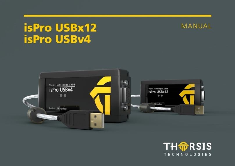
Thorsis Technologies isHRT USB User manual

MANUAL
isHRT USB
isHRT USBeX
the H@rt BluePack

2
Hereby we declare that the devices referred to below in their
design and construction, are in conformity with the essential safety
and health requirements of the EC-Directive 2014/30/EU. Changes or
modifications not approved by Thorsis Technologies void the validity
of the declaration.
Device type Order numbers
isHRT USB 14300-0102
isHRT USBeX 14300-0201
the H@rt BluePack 14300-2002
Magdeburg, 2018-08-28
Dipl.-Ing. Thorsten Szczepanski,
Managing director
STANDARDS USED: EN 61326-1:2013
Manufacturer
Thorsis Technologies GmbH
Oststr. 18
39114 Magdeburg
Germany
The interface type isHRT USBeX has been tested for the use in poten-
tially explosive atmospheres according to the EC-Directive 2014/34/EU.
A TÜV CERT Certification Body has certified, that the device meets
the provisions of the Directive in the essential health and safety
requirements for the conceptional design and manufacturing of
equipment, protection systems and devices set out in Annex II of the
Directive, in account being taken of their intended use in potentially
explosive atmosphere. The EC equipment type examination number
is TÜV 04 ATEX 2503.
The responsible Certification Body is:
TÜV NORD CERT GmbH
Division Technology
Am TÜV 1
30519 Hannover
Germany
The interface type was tested according to:
EN 60079-0:2012+A11:2013 and EN 60079-11:2012-06.
CERTIFICATE OF CONFORMITY

3
Table of Content
1. ISHRT USB AND ISHRT USBEX – HART ON USB . . . . . . . . . . . . 4
1.1 Technical details . . . . . . . . . . . . . . . . . . . . . . . . . . . . . . . . . . . . 5
1.2 Delivery content . . . . . . . . . . . . . . . . . . . . . . . . . . . . . . . . . . . . 5
2. THE H@RT BLUEPACK – HART ON BLUETOOTH/USB . . . . . . . 6
2.1 Technical details . . . . . . . . . . . . . . . . . . . . . . . . . . . . . . . . . . . . 7
2.2 Delivery content . . . . . . . . . . . . . . . . . . . . . . . . . . . . . . . . . . . . 7
2.3 Operation of the unit . . . . . . . . . . . . . . . . . . . . . . . . . . . . . . . . 8
2.3.1 Battery operation . . . . . . . . . . . . . . . . . . . . . . . . . . . . 8
2.3.1.1 Switch on the device . . . . . . . . . . . . . . . . . . . . 8
2.3.1.2 Switch off the device . . . . . . . . . . . . . . . . . . . 8
2.3.2 USB operation . . . . . . . . . . . . . . . . . . . . . . . . . . . . . . . 8
3. INSTALLATION OF THE DRIVER SOFTWARE . . . . . . . . . . . . . . 9
4. INSTALLATION OF THE ISHRT COMM DTM . . . . . . . . . . . . . . 10
5. INSTALLATION OF THE HARDWARE – ISHRT USB . . . . . . . . . 11
6. INSTALLATION OF THE HARDWARE – ISHRT USBEX. . . . . . . 12
7. INSTALLATION OF THE HARDWARE – THE H@RT BLUEPACK 13
7.1 Coupling the H@rt BluePack via Bluetooth . . . . . . . . . . . . . 14
8. CONFIGURATION AND COMMISSIONING . . . . . . . . . . . . . . . 16
8.1 Add a USB device . . . . . . . . . . . . . . . . . . . . . . . . . . . . . . . . . . 17
8.2 Add a Bluetooth device . . . . . . . . . . . . . . . . . . . . . . . . . . . . . 18
8.3 Add an Empty-Slot . . . . . . . . . . . . . . . . . . . . . . . . . . . . . . . . . 19
8.4 Removal of a device . . . . . . . . . . . . . . . . . . . . . . . . . . . . . . . . 19
9. ISHRT TEST. . . . . . . . . . . . . . . . . . . . . . . . . . . . . . . . . . . . . . . . 20
10. FDT COMMUNICATION-DTM ISHRT COMMDTM . . . . . . . . . 20
11. OFFLINE CONFIGURATION ISHRT COMMDTM . . . . . . . . . . . 21
11.1 Driver configuration . . . . . . . . . . . . . . . . . . . . . . . . . . . . . . . . 21
11.2 Channel Configuration. . . . . . . . . . . . . . . . . . . . . . . . . . . . . . 22
11.3 Connecting DeviceDTMs . . . . . . . . . . . . . . . . . . . . . . . . . . . . 23
12. ONLINE CONFIGURATION OF THE ISHRT COMMDTM . . . . . 24
12.1 Device List . . . . . . . . . . . . . . . . . . . . . . . . . . . . . . . . . . . . . . . . 24
12.2 Changing Polling Address . . . . . . . . . . . . . . . . . . . . . . . . . . . 26
12.3 Changing Polling Address, DeviceDTM Address and Tag . . 27
13. DOCUMENT HISTORY . . . . . . . . . . . . . . . . . . . . . . . . . . . . . . . 28

4
1. isHRT USB and isHRT USBeX – HART on USB
The interface isHRT USB is designed to provide a communication link
between a desktop computer or PC notebook and the HART field
device. The PC can be taken into the field and connected with the HART
network within seconds thanks to the USB plug & play features. Mobile
data acquisition as well as parameterization are preferred operational
areas. The modem can work as primary as well as secondary Master and
features galvanic decoupling from the HART line.
For the use in hazardous areas we deliver an intrinsic safe, ATEX
certified version: isHRT USBeX. It is functionally equivalent to the
standard type.

5
1.1 Technical details
1.2 Delivery content
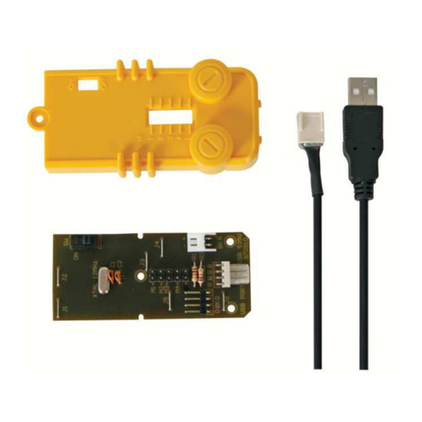
USB-HART-Modem “isHRT USB” or ”isHRT USBeX”, HART-Driver, isHRT CommDTM, PACTware and
documentation in German and English on CD.
Interface isHRT USB isHRT USBeX
Modem Chip DS8500 HT2012
Connector 2-pole current terminal
Transmission rate 1200 Bit/s (600 Bit/s optional)
Safety engineering data UO: 1,0 V; IO: 7 mA; P
O: 7 mW, LI≈0 mH; CI=1,2 μF; Uin: 5,5 V;
Iin: 200 mA; Pin: 1 W; Um253 V
Size (WxDxH) in mm 97 x 47 x 24 89 x 50 x 24
Weight 158 g 243 g
Cable length ≈1,5 m USB & HART
Driver software Windows XP, Vista, Windows 7,8 & 10
Compatible with
Simatic PDM© Siemens, HCF-Server
Emerson AMS Device Manager
PACTware
Endress+Hauser FieldCare
ABB Asset Vision Basic

6
2. the H@rt BluePack – HART on Bluetooth/ USB
“the H@rt BluePack” is a versatile interface which supports wireless
(Bluetooth) and wired (USB) access to a HART network. It can be em-
ployed as an up-to-date replacement for the still widely used RS-232-
HART modem solutions. Additionally to its modem capabilities
the H@rt BluePack runs an embedded HART master stack.
The active HART master stack guarantees compliance with the HART
timing requirements regardless of the speed of the PC host appli-
cation or the data transmission quality between the host and the
Bluetooth device. This can be of considerable advantage if using
the interface in multi-master environments or in connection with
burst-mode slaves. The stack can be configured to work as primary
or secondary master.
The interface can be powered via the USB connection or 3 replaceable
AAA cells. If operating in battery mode it can be powered down by
an on/off-button. To increase the life span of the batteries the device
switches to sleep mode if no Bluetooth communication takes place.
The activity on the HART network is indicated by one LED.

7
2.1 Technical details
Interface the H@rt BluePack
Bluetooth Modem WT11 (Bluegiga)
HART Modem Chip DS 8500
Connector 2-pole current terminal / Mini-USB
Transmission rate USB: 12Mbit/s; HART: 1200 Bit/s; Bluetooth: up to 2,1 Mbit/s
Power supply 3 x AAA Batteries or USB-cable
Size (WxDxH) in mm 84 x 54 x 26
Weight 106g (without Batteries)
Cable length ≈1,5 m
Driver software Windows XP, Vista, Windows 7, 8, 10
Compatible with
Simatic PDM© Siemens, HCF-Server
Emerson AMS Device Manager
PACTware
Endress+Hauser FieldCare
ABB Asset Vision Basic
2.2 Delivery content
HART-Bluetooth Modem “the H@rt BluePack”, HART-Driver, isHRT CommDTM, PACTware and documentation in German and English on CD.

8
2.3 Operation of the unit
2.3.1 Battery operation
2.3.1.1 Switch on the device
• There is a button at the front of the device, which can be used to
switch the device on. Switching on is signaled by the LED blinking
three times. After switching on, the device is ready for a Bluetooth
connection.
• The LED flashes briefly at regular intervals to indicate whether the
device is switched on or off.
Two different operating modes are signaled:
1. In the first minute after power up, the device is visible to other
Bluetooth devices, i.e. the H@rt BluePack can be paired with other
devices. This operating mode is indicated by two short flashes of
the LED every 4 seconds.
2. One minute after switching on the device becomes invisible to
other Bluetooth devices, so they can no longer find the H@rt
BluePack and thus no longer be paired to it. Of course, devices
that are already paired can continue to connect to the H@rt
BluePack. In this operating mode the LED flashes briefly every 10s.
2.3.1.2 Switch off the device
To switch off, press the button on the front of the device until
the LED switches on (approx. 3 seconds).
The LED signals the switch-off process by gradually darkening.
When the LED is completely dark, the device is switched off.
2.3.2 USB operation
• As soon as the device is connected to a PC via USB, the device is
switched on and active – the button has no function when the
power is supplied via a USB cable.
• Communication with the device can take place via USB or via
Bluetooth. It is also possible to pair with other Bluetooth devices
at any time.
• The use of USB power supply adapters for the power supply of
the H@rt-BluePack is not possible.
LED
Button
Mini USB-Connector

9
3. Installation of the driver software
The driver software should be installed before connecting the device.
Otherwise, the operating system can not find the interface to the associated driver.
The driver software package isHRT Multidriver contains a Dynamic Link Library (DLL) which allows the access to the
HART firmware under the operating systems Windows 7, 8 und 10.
The actual operating system is detected automatically by the driver DLL.
The configuration of the interface can be done with the configuration software isHRT Driver Configurator
which is installed into the Thorsis Technologies directory of the Start Menu.
Installation process:
• Login as administrator
• Insert the installation CD-ROM
• The setup starts with an autoroutine; proceed according to the instructions displayed on the screen.
Should Autorun be disabled on your machine, run the “isHRT_Driver_Setup.exe” on the installation CD.
The installation is done in the standard program directory of the target machine under:
“C:\Program Files (x86)\Thorsis Technologies\isHRT Driver 64bit”.

10
4. Installation of the isHRT CommDTM
The operation of the software isHRT FDT requires the correct installation of the HART interface isHRT USB and isHRT USBeX respectively.
The driver software delivered with our interface permits the access to the HART Firmware.
The interface between application and HART firmware comes in the shape of a Dynamic Link Library (DLL).
The delivered software isHRT FDT supports the operating systems Windows Vista, XP and Windows 7, 8, 10 (32-bit/64-bit).
It is placed on the enclosed CD.
The installation follows the steps mentioned below:
• Insert the installation CD into your drive.
• Start “isHRT CommDTM v2 Setup.exe” and proceed according to the instructions displayed on the screen.
The software is installed in the default program directory of your computer under the subdirectory:
”C:\Program Files (x86)\Thorsis Technologies\isHRT CommDTM”.
Install the driver before connecting the modem!
Otherwise the modem may not be recognized correctly.

11
5. Installation of the hardware – isHRT USB
The interface can be connected to the HART network with the pin
test clips directly. With the integrated USB cable the interface can be
connected with the PC / notebook.
The device is equipped with a green LED, which indicates the oper-
ating state. It lights up when the software is initialized. When the
software stops working with the device, the LED is switched off.
PLC
24 VSlave
Engineering
station
Engineering
station
1. Instructions for Installation with a PLC
2. Instructions for Installation with a 24 V power source
Slave
240 Ω

12
6. Installation of the hardware – isHRT USBeX
The interface can be connected to the HART network with the pin
test clips directly. With the integrated USB cable the interface can be
connected with the PC / notebook.
The device is equipped with a green LED, which indicates the oper-
ating state. It lights up when the software is initialized. When the
software stops working with the device, the LED is switched off.
24 V
Slave
Engineering
station
2. Instructions for Installation with a 24 V power source
240 Ω
Safe area
Hazardous area

13
7. Installation of the hardware – the H@rt BluePack
PLC PLC
24 V 24 VSlave Slave
Engineering
station
Engineering
station
Engineering
station
Engineering
station
1. Instructions for Installation with a PLC
USB Bluetooth
1. Instructions for Installation with a PLC
2. Instructions for Installation with a 24 V power source 2. Instructions for Installation with a 24 V power source
Slave Slave
240 Ω 240 Ω

14
7.1 Coupling the H@rt BluePack via Bluetooth
Click on “Add a Device”
(“Add a Bluetooth Device” in Windows 10)
To be able to use the H@rt BluePack, it must first be coupled to the
host computer. This step is necessary only once. First, insert the 3
AAA batteries. Activate the H@rt BluePack by briefly pressing the
button next to the mini USB socket.
After power on, the device is visible for one minute to other
Bluetooth devices (see chapter 2.3).
Activate Bluetooth in the Control Panel of your computer.
Click on the Bluetooth icon in the taskbar to open
the context menu

15
Select the H@rt BluePack from the list.
In the appropriate dialog box, enter the four-digit “key” of the
device, located on the sticker at the front of the device.
The device is ready for use as soon as you can read “Paired“
under the H@rt BluePack.
The device is now paired with your PC.
The COM interface displayed is necessary for the later configuration.
But you can also display this through the Control Panel/ Blue-
tooth/network devices later.
Now you will be prompted to enter the PIN

16
8. Configuration and commissioning
The configuration software isHRT Driver Configurator is provided
in order to adapt the DLL access to your hardware. It is installed
in the Start Menu. This dialog based application allows the easy
addition and removal of HART interfaces. It also checks the avail-
able resources of the system.
A device number is assigned to each USB interface which enables
the software to address it. Empty devices can be included in order
to allow gaps in the enumeration of devices; see section “8.3 Emp-
ty-Slot” on page 19.
Run this program as an administrator.

17
8.1 Add a USB device
Please press the button “Add”, choose the device type you would
like to add. Press “OK”, then make your settings.
The device has a unique serial number for clear identification.
The number is located on the bottom of the case. The configura-
tion software offers the possibility to search automatically for all
attached devices and to detect their serial numbers. Please fill in
the number in the intended field.
The device can work like a serial modem under the operating
systems Windows 7, 8 und 10. In order to facilitate this, it offers a
serial COM-port so that already existing applications can be used
without any changes. The serial COM-port can be selected. The
configuration software checks the available COM-ports to avoid
an address conflict.
Finish your settings by clicking “OK”.

18
8.2 Add a Bluetooth device
When you add a Bluetooth device, you can choose between USB
and Bluetooth connection.
If you select a USB connection, you must enter the serial number
or can let the program automatically search for a connected the
H@rt-BluePack.
Click on “OK”
When selecting a Bluetooth connection, you must select the
assigned COM port. You can also do this under Control Panel /
Bluetooth / network access devices.
Click on “OK”

19
8.3 Add an empty slot
8.4 Removal of a device
Mark the device you wish to remove and press the button “Remove”. You can then remove the device from the USB port.
The empty device does not contain any resources. It serves as a
substitute for device numbers not yet assigned. Using empty slots
enables a free enumeration of devices by inserting empty devices
between existing ones.

20
9. isHRT Test
The correct installation and functionality of isHRT USB can be
checked with the test application “isHRT Testprogram” in the
driver software.
The program searches for connected HART slaves.
10. FDT Communication-DTM isHRT CommDTM
The isHRT CommDTM is a CommDTM for the interfaces isHRT USB
and isHRT USBeX. The DTM offers communication access via the isH-
RT Channel as explained earlier. This chapter describes the configu-
ration of the isHRT CommDTM. The configuration can be accessed by
selecting the function “Channel Configuration” offered by the isHRT
CommDTM. The configuration dialog is only available in offline
mode, i.e. the DTM is not connected.
The software isHRT CommDTM can be integrated into any stand-
alone frame application (e.g. PACTware, FieldCare). After the instal-
lation of the software (see „4. Installation of the isHRT CommDTM“
on page 10), the CommDTM is ready for use. In order to actually use
the CommDTM, it is necessary to start the frame application. Then,
the device catalogue of the Frame Application has to be updated.
Now, the isHRT CommDTM is registered and ready for work.
This manual suits for next models
2
Table of contents
Other Thorsis Technologies USB Interface manuals