Praxisdienst ES-100V User manual


Introduction to product manual
ii
Introduction
The manual applies only to the company's high-frequency surgical
generator (hereinafter referred to as "surgical generator"), which is
only used in medical institutions and is only used by medical staff
who have been trained and qualified in surgery and specific
techniques. For other technical information about the surgical
generator, please refer to the after-sales service manual of the
company's high-frequency surgical generator.
Note
This surgical generator can be only used by medical staff who
have been trained and qualified in surgery and specific
techniques.
Overview of the manual
Product name: high-frequency surgical generator;
Model: ES-100V
Date of manufacture: please refer to the brand tag of the surgical
generator;
Expiration date: 6 years;
Version: SJR-IT-202102001-1.0;
Compilation/Revision:.

Introduction to product manual
iii
Instructions for use of the manual
Warning
It indicates a potentially hazardous condition which, if not
avoided, will result in death or serious injury.
Note
It indicates a hazardous condition which, if not avoided, will
result in mild or moderate injuries.
Important note
It refers to the tips and suggestions for the generator operation.
Caution
It indicates a condition that affects the quality of the product,
which, if not avoided, will do damage to the product.
Description
It refers to explanation.

Contents of product manual
V
Contents
Introduction....................................................................ii
Instructions for use of the manual...............................iii
Contents......................................................................... V
Part One Introduction to High Frequency Electrotome- 1 -
1.1 Introduction to the surgical generator ........... - 2 -
1.2 Software description ..................................... - 2 -
1.3 Monopolar mode........................................... - 2 -
1.4 Bipolar mode................................................. - 3 -
1.6 Structure and composition .............................. -4-
1.7 Range of application ..................................... - 3 -
1.8 Contraindication............................................ - 3 -
Part two front panel, back panel, figures and symbols - 4 -
2.1 Front panel .................................................... - 5 -
2.2 Bipolar controller .......................................... - 6 -
2.3 Bipolar output interface ................................ - 7 -
2.4 Monopolar electrosurgical excision controller- 8
-
2.5 Monopolar electro-coagulation controller..... - 9 -
2.6 Monopolar output interface......................... - 10 -
2.7 Return electrode interface ........................... - 10 -
2.9 Foot switch socket....................................... - 13 -
2.10 Power input module ................................ - 13 -
2.11 Figures and symbols.................................. - 14 -
Part three safety guidelines for the surgical generator- 19
-
3.1 Overview of the safety guidelines............... - 20 -
3.1.1 Training............................................ - 20 -
3.1.2 Fire and explosion............................ - 20 -
3.1.3 Maintenance..................................... - 20 -
3.2 Pre-surgery guidelines................................. - 21 -
3.2.1 Accessories activation ...................... - 21 -
3.2.2 Return electrode ............................... - 21 -
3.2.3 Host machine of the surgical generator....-
22 -
3.2.4 Others............................................... - 23 -
3.3 Guidelines for the ongoing surgery............. - 24 -
3.3.1 Power settings .................................. - 24 -
3.3.2 Bipolar tweezers............................... - 24 -
3.3.3 Contact with metal objects ............... - 24 -
3.3. 4 Activated accessories ...................... - 24 -
3.3. 5 Return electrode...............................- 25 -
3.3. 6 Others ..............................................- 25 -
3.4 Post-surgery guidelines ...............................- 26 -
Part four Preparation before the surgery....................- 27 -
4.1 Host machine preparation............................- 28 -
4.2 Bipolar surgical preparation ........................- 30 -
4.2.1 Connection of the bipolar generator
accessories ................................................- 30 -
4.3 Monopolar surgical preparation...................- 31 -
4.3.1 Connection of the monopolar generator
accessories.................................................- 31 -
4.3.2 Attach the return electrode to the patient. -
32 -
4.3. 3 Monopolar output setting and testing- 32
-
4.4 Parameter memory preparation ...................- 33 -
Part five the ongoing surgery ....................................- 34 -
5.1 Check the connection of power supply and
accessories.........................................................- 35 -
5.2 Check the connection of return electrode ....- 35 -
5.3 Mode selection, power setting and power change
...........................................................................- 35 -
5.3.1 Mode selection and power setting ....- 35 -
5.3. 2 Power change .................................- 35 -
5.4 Surgical electrode activation .......................- 36 -
5.4.1 Monopolar mode electrode activation .. -
36 -
5.4. 2 Bipolar mode electrode activation - 36 -
5.5 Indicator lights activation............................- 36 -
5.6 Volume control ............................................- 36 -
5.7 Response to the alarm information..............- 38 -
5.7.1 REM sound and light alerting signals- 38
-
5.7.3 Error code.........................................- 38 -
5.7.4 Fault alarm........................................- 38 -
Part six Post-surgery..................................................- 39 -
6.1 Prepare for the next use...............................- 40 -
6.1.1 Remove the accessories....................- 40 -
6.1.2 Cleaning............................................- 40 -
6.2 Storage of the surgical generator.................- 41 -

Contents of product manual
Vi
Part seven Fault analysis and troubleshooting .......... - 42 -
7.1 Fault analysis and troubleshooting.............. - 43 -
7.2 Common error code .................................... - 44 -
Part eight Maintenance and repair ............................ - 45 -
8.1 Care and maintenance ................................. - 46 -
8.1.1Check frequency and check items of the
surgical generator...................................... - 46 -
8.1.2 Check the power line, electrode wire and
foot switch wire......................................... - 46 -
8.1.3 Fuse replacement.............................. - 46 -
8.1.4 Cleaning and disinfection of the product
and accessories.......................................... - 46 -
8.2 Repair.......................................................... - 48 -
8.2.1 Accessories replacement ................ - 48 -
8.2.2 Depot Repair .................................... - 48 -
8.3 Scrapping of the generators and accessories- 49 -
8.4 After-sales service center ............................ - 49 -
Part nine Technical features ...................................... - 50 -
9.1 Performance features................................... - 51 -
9.1.1 Appearance....................................... - 51 -
9.1.2 Performance ..................................... - 51 -
9.1.3 Frequency......................................... - 51 -
9.1.4 Alarm information............................ - 52 -
9.1.5 Security features ...............................- 52 -
9.1.6 Fuse ..................................................- 52 -
9.1.7 Surgical accessories..........................- 52 -
9.1.8 Packaging .........................................- 53 -
9.1.9 Storage and transportation................- 53 -
9.2 Available power value................................- 54 -
9.3 Curve graph of output power to the resistance... -
55 -
9.3.1 Monopolar pure cut ..........................- 55 -
9.3.2 Monopolar blend cut 1......................- 56 -
9.3.3 Monopolar blend cut 2......................- 56 -
9.3. 4 Monopolar spray coagulation.......- 57 -
9.3. 5 Monopolar forced coagulation.........- 57 -
9.3. 6 Bipolar standard mode..................- 58 -
Part ten Electromagnetic compatibility .....................- 59 -
Precautions.......................................................- 60 -
Table 1: electromagnetic radiation ....................- 61 -
Table 2: electromagnetic immunity 1 ................- 61 -
Table 3: electromagnetic immunity 2 ................- 63 -
Table 4: recommended safe distance.................- 65 -
Exceptional situations .....................................- 67 -

Product manual. Part two front panel, back panel, figures and symbols
- 1 -
Part One Introduction to high-frequency surgical generator;
Contents of this part include:
1.1 Introduction to the surgical generator
1.2 Software description
1.3 Monopolar mode
1.4 Bipolar mode
1.5 Return electrode monitor system
1.6 Structure and composition
1.7 Range of application
1.8 Contraindication
For the safety of the medical staff and patients, medical staff
should read this manual carefully to have an in-depth knowledge
of this surgical generator.

Product manual. Part two front panel, back panel, figures and symbols
- 2 -
1.1 Introduction to the surgical generator
Product is a multi-functional high frequency surgical generator with
6 kinds of operating modes, including 3 kinds of monopolar
electrosurgical excision modes, 2 kinds of monopolar
electro-coagulation modes and 1 kind of bipolar modes. It provides
great convenience for a variety of surgeries with the help of the
electrotome. At the same time, the built-in return electrode monitor
system is capable of monitoring high frequency leakage current,
thus providing safety assurance for surgery.
It has the following features:
●3 kinds of monopolar electrosurgical excision modes: pure cut,
blend cut 1, blend cut 2;
●2 kinds of monopolar electro-coagulation modes: spray
coagulation, forced coagulation;
●1 kinds of bipolar output modes: standard mode;
●Manual switch and foot switch;
●The recently used mode, power and other parameters can be
invoked when starting up;
●Volume control function;
●Intermittent cutting alternating with blood coagulation.
1.2 Software description
Software name: High frequency surgical generator t firmware
Software version: V1.0
Software functions: please refer to the introduction to each
controller in part two.
1.3 Monopolar mode
● The monopolar modes of this surgical generator include
monopolar electrosurgical excision mode and monopolar
electro-coagulation mode, among which the electrosurgical excision
modes include pure cut, blend cut 1, blend cut 2 and their respective
output powers are adjustable.
◆ Pure cut: Unmodulated sine wave. Clean and precise tissue cutting
can be performed if there is no need for hemostasis.
◆ Blend cut 1: The first sine wave to be modulated. It is used when
the cutting speed is a bit slow and there is only a small amount of
bleeding needed to be treated.
◆ Blend cut 2: The second sine wave to be modulated. Compared
with blend cut 1, it is used when the cutting speed is a little bit slower
and a better hemostasis effect is needed.

Product manual. Part two front panel, back panel, figures and symbols
- 3 -
● Monopolar electro-coagulation modes include spray coagulation,
forced coagulation and their respective output powers are
adjustable.
◆ Spray coagulation: non-contact efficient surface
electro-coagulation with shallow penetration. The tissue removal is
achieved by evaporation and a knife-shaped or a spherical electrode
is usually adopted for blood coagulation.
◆ Forced coagulation: non-contact blood coagulation, but the output
peak voltage is lower than that of the spray coagulation. It applies to
blood coagulation of small area.
In regard to the output features of the monopolar mode, please refer
to part nine-technical features.
1.4 Bipolar mode
●The bipolar mode only has the standard mode.
◆Standard: Suitable for most bipolar applications. Keep the voltage
low to prevent sparks.
Regarding the output characteristics of the bipolar mode, see Part
9-Technical Features.
1.5 Structure and composition
The high-frequency surgical generator is composed of a host, a
power cord, a pedal, an electrode, and a neutral plate.
1.6 Range of application
Electrosurgical generator is a general electrosurgical generator
designed to generate radio frequency (RF) current, which is used for
the cutting and coagulation of the target tissues through the
accessory generators during opening and laparoscopic surgery.
1.7 Contraindication
High-frequency surgical generator belongs to surgical products, and
its contraindication is related to particular electrosurgical
operations. There are no absolute contraindications for the generator
itself. Patients with implantable cardiac pacemakers or other metal
implants should be treated with caution and high-frequency current
should be avoided to flow near the implants.

Product manual. Part two front panel, back panel, figures and symbols
-4 -
Part two front panel, back panel, figures and symbols
Contents of this part include:
2.1 Front panel
2.2 Bipolar controller
2.3 Bipolar output interface
2.4 Monopolar electrosurgical excision controller
2.5 Monopolar electro-coagulation controller
2.6 Monopolar output interface
2.7 Return electrode interface
2.8 Back panel
2.9 Foot switch socket
2.10Power input module
2.11 Figures and symbols

Product manual. Part two front panel, back panel, figures and symbols
-5 -
2.1 Front panel
①Monopolar electro-coagulation controller
In the monopolar electro-coagulation mode, there are different mode
selections and power value settings.
②Monopolar electrosurgical excision controller
In the monopolar electrosurgical excision mode, there are different mode
selections and power value settings.
③Bipolar mode
④Bipolar output interface
⑤Monopolar output interface
⑥Return electrode interface
⑦Power switch
Generator power switch.
"┃" means "on" and "○" means "off".

Product manual. Part two front panel, back panel, figures and symbols
- 6 -
2.2 Bipolar controller
①Bipolar mode indicator
The indicator light is on to indicate that the bipolar mode is
being used.
②Power increase button in bipolar mode
Press this key to increase the power (P) of the selected mode,
1W/time, long press to increase continuously.
③Power reduction button in bipolar mode
Press this key to decrease the power (P) of the selected mode,
1W/time, long press to decrease continuously.
④Bipolar mode selection key
Press the piezoelectric coagulation mode selection key to enter
the bipolar mode, and the indicator light of the selected mode is on.
⑤Bipolar standard mode indicator
The indicator light is on to indicate that the bipolar standard
mode has been selected, and the rated output power is 60W.
⑥Power output display
Display the output power (W) set when a certain bipolar mode is
selected by the device.

Product manual. Part two front panel, back panel, figures and symbols
- 7 -
2.3 Bipolar output interface
This interface only supports two-pin bipolar generator accessories.
Bipolar generators can be connected to this gang socket for bipolar
electro-coagulation. Bipolar foot switch can be used to start the
bipolar electro-coagulation mode.
Note
The interface is limited to bipolar generator accessories that shall
meet the requirements of part nine. The use of substandard
accessories may result in the failure to plug and start up, REM
alarm, abnormal output and so on.
Objects such as tweezers, metal needles are not allowed to insert
into this output interface, which might lead to electric shock.
Product manual. Part two front panel, back panel, figures and symbols
- 8 -
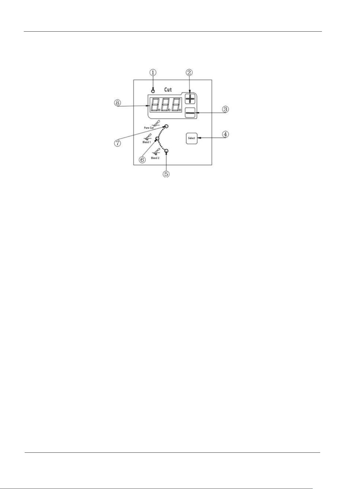
2.4 Monopolar electrosurgical excision controller
①Indicator light in the electrosurgical excision mode
If the indicator light is on, it means that the electrosurgical excision mode has been selected.
②Power amplification button in the electrosurgical excision mode
Press the button to increase the power (P) of the selected mode,, 1 W/ time. Long press on the button
and the power will keep increasing.
③Power reduction button in the electrosurgical excision mode
Press the button to reduce the power (P) of the selected mode , 1 W/ time. Long press on the button and
the power will keep decreasing.
④Electrosurgical excision mode selection button
Press this button to select from four different electrosurgical excision modes and the indicator light of
the selected mode will be on.
⑤Indicator light in the blend cut 2 mode
If the indicator light is on, it means that the blend cut 2 mode has been selected and the rated output
power is 100W.
⑥Indicator light in the blend cut 1 mode
If the indicator light is on, it means that the blend cut 1 mode has been selected and the rated output
power is 100W.
⑦Indicator light in the pure cut mode
If the indicator light is on, it means that the pure cut mode has been selected and the rated output power
is 100W.
⑧Electrosurgical excision power output display screen
Display the output power (W) set for a certain selected monopolar electrosurgical excision mode.
Product manual. Part two front panel, back panel, figures and symbols
- 9 -
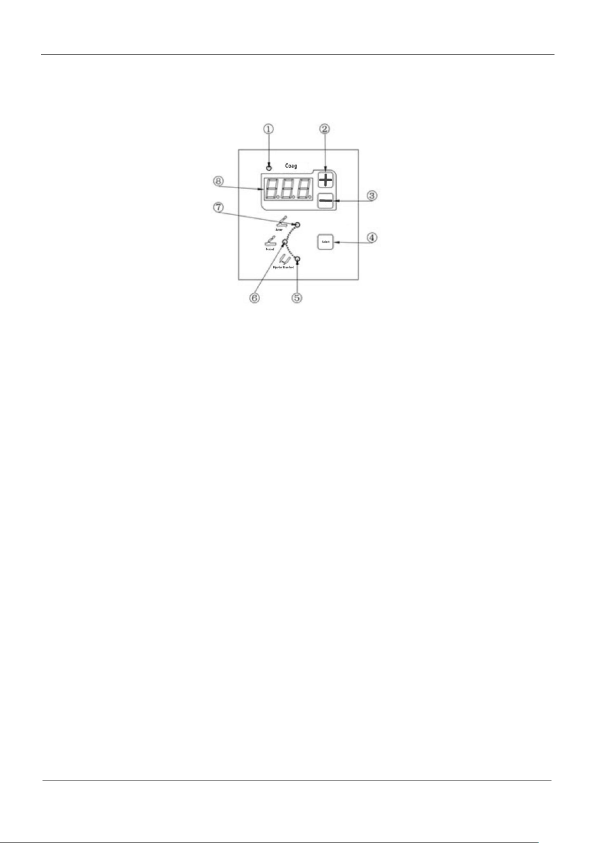
2.5 Monopolar electro-coagulation controller
①Indicator light in the electro-coagulation mode
If the indicator light is on, it means that the electro-coagulation
mode has been selected.
②Power amplification button in the electro-coagulation mode
Press the button to increase the power (P) of the selected mode, 1
W/ time, Long press on the button and the power will keep
increasing.
③Power reduction button in the electro-coagulation mode
Press the button to reduce the power (P) of the selected mode, 1 W/
time, Long press on the button and the power will keep decreasing.
④Electro-coagulation mode selection button
Press this button to select from three different electro-coagulation
modes and the indicator light of the selected mode will be on.
⑤Indicator light in the forced coagulation mode
If the indicator light is on, it means that the forced coagulation
mode has been selected and the rated output power is 60W.
⑦Indicator light in the spray coagulation mode
If the indicator light is on, it means that the spray coagulation mode
has been selected and the rated output power is 90W.
⑧Electro-coagulation power output display screen
Display the output power (W) set for a certain selected
electro-coagulation mode.
Product manual. Part two front panel, back panel, figures and symbols
- 10 -
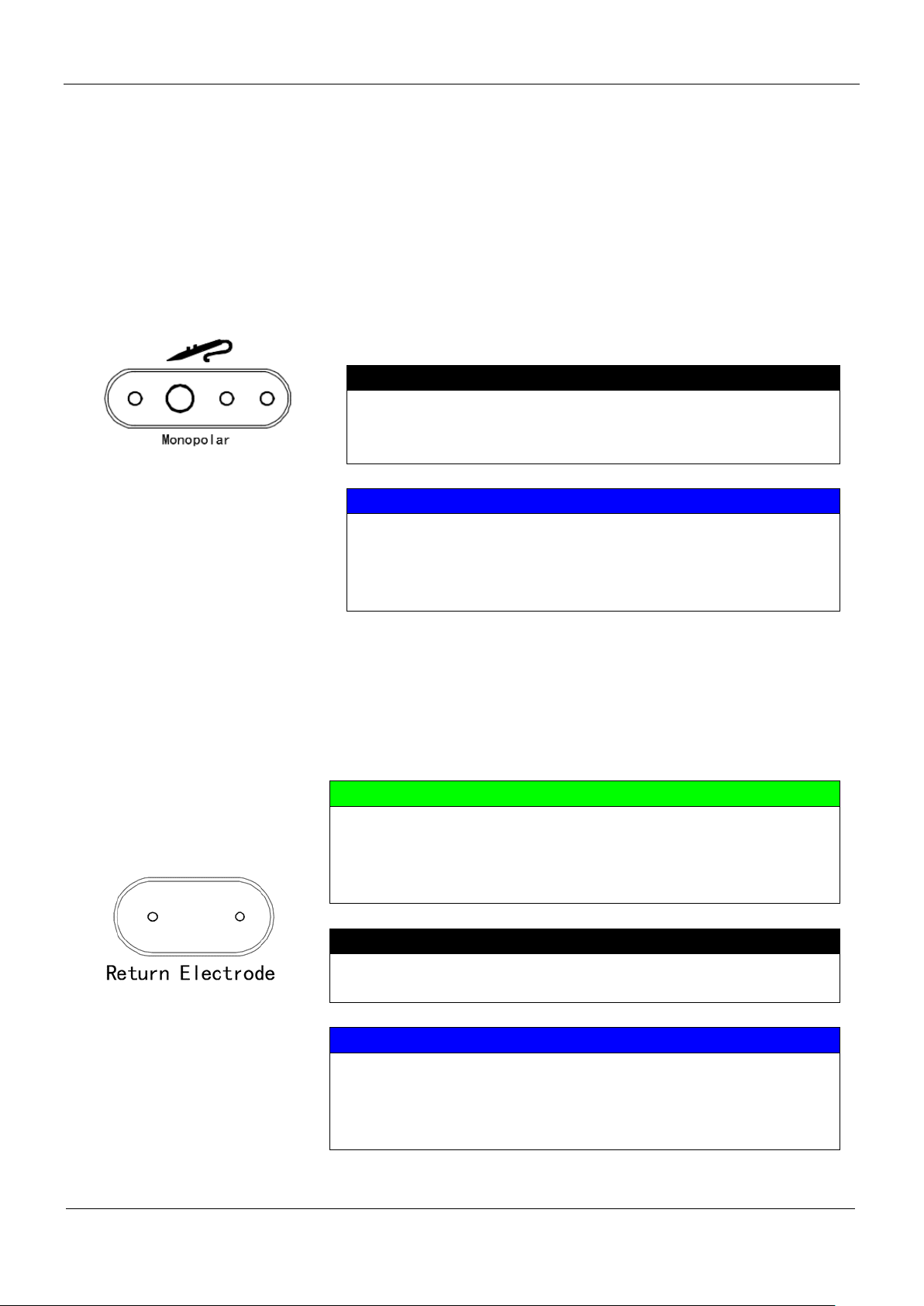
2.6 Monopolar output interface
Monopolar output interface
The monopolar handle can be connected to the interface for
electrosurgical excision or monopolar electro-coagulation.
Monopolar foot switch or the switch on the monopolar handle can
be used to start the electrosurgical excision or monopolar
electro-coagulation modes. In regard to the operation of the
monopolar handle, please refer to part five.
Warning
Objects such as tweezers, metal needles are not allowed to
insert into this output interface, which might lead to electric
shock.
Note
This interface is limited to monopolar generator accessories
that shall meet the requirements of part nine. The use of
substandard accessories may result in the failure to plug and
start up, REM alarm, abnormal output and so on.
2.7 Return electrode interface
Monopolar cut or electro-coagulation requires the use of appropriate
return electrodes, which have to be connected to the generator and
be attached to the patient as well.
Important note
The generator is equipped with return electrode security system -
the "return electrode detection function", which can automatically
monitor the connection between the return electrode and the
generator and the contact area on the patient.
Objects such as tweezers, metal needles are not allowed to insert
into this output interface, which might lead to electric shock.
Note
This interface is limited to return electrode generator accessories
that shall meet the requirements of part nine. The use of
substandard accessories may result in the failure to plug and start
up, REM alarm, abnormal output and so on.

Product manual. Part two front panel, back panel, figures and symbols
- 11 -
Product manual. Part two front panel, back panel, figures and symbols
- 12 -
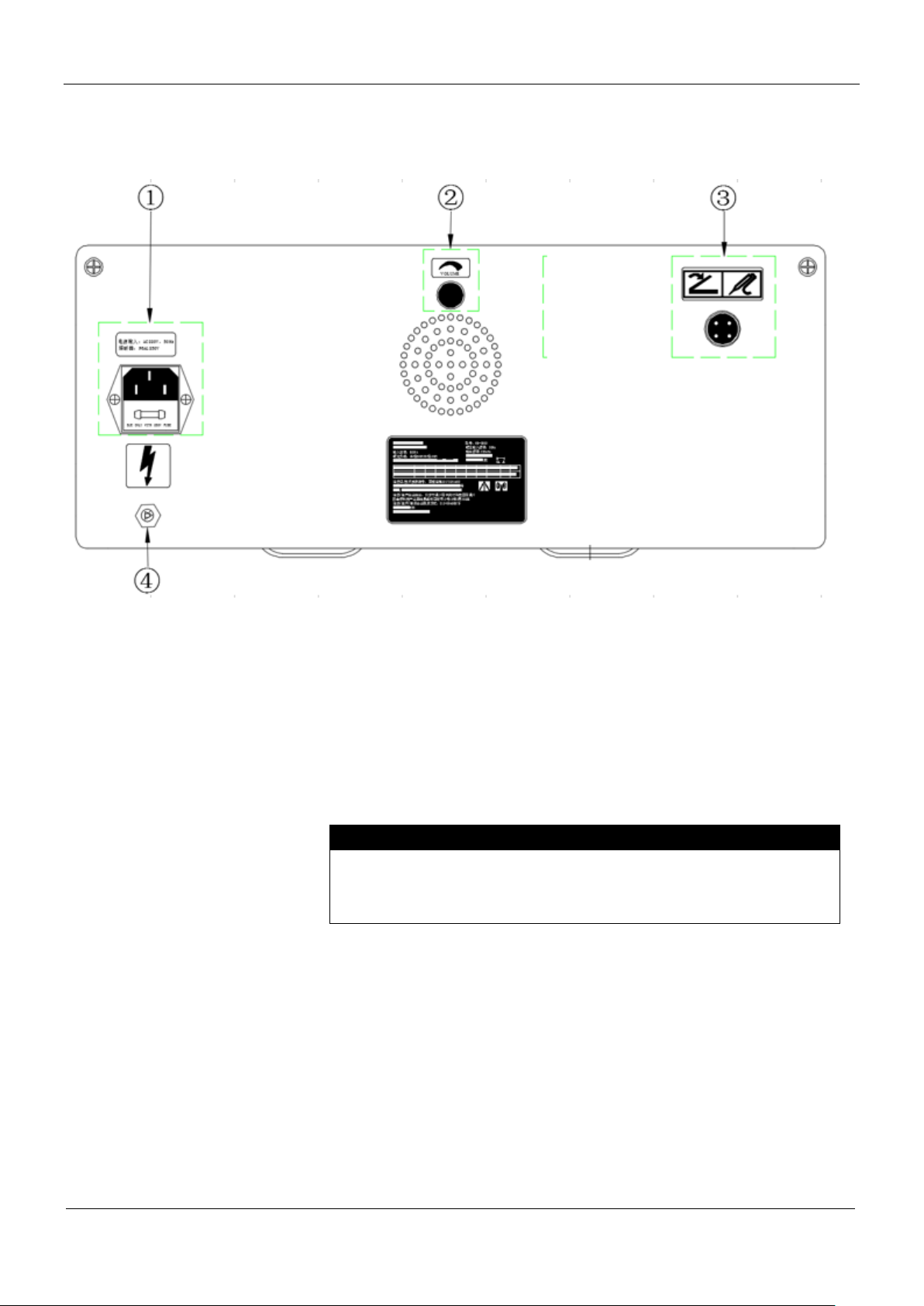
2. 8 Back panel
①Power input module
②Audio frequency and volume knob
To control the volume of the sound signals. Turn clockwise to
increase the volume and turn counterclockwise to decrease the
volume.
③Monopolar foot switch socket
④Equipotential earth terminal
Connect the generator to the ground.
⑤ Bipolar foot switch socket
It is not allowed to mute the volume of the generator, which may
result in the failure for the surgical staff to notice the accidental
start-up of the generator or the REM alarm information.

Product manual. Part two front panel, back panel, figures and symbols
- 13 -
2.9 Foot switch socket
Monopolar and Bipolar foot switch socket
Use together with the monopolar foot switch.
Note
Foot switch socket belongs to generator accessory and it shall
meet the requirements in part nine. The use of substandard
accessories may result in the failure to plug and start up, REM
alarm, abnormal output and so on.
2.10 Power input module
The power input module consists of the power line socket and the
fuse (protective tube) drawer.
①Power line socket
Use together with the power line plug of the surgical generator.
②Fuse (protective tube) drawer
There are 2 tubular fuses in this drawer. Please refer to part seven
for more information about disassembly,examination, maintenance
and replacement.
The use of power line that is not supplied by the manufacturer
may result in electric shock and fire.
Caution
The use of fuse that is not supplied by the manufacturer may do
damage to the product.

Product manual. Part two front panel, back panel, figures and symbols
- 14 -
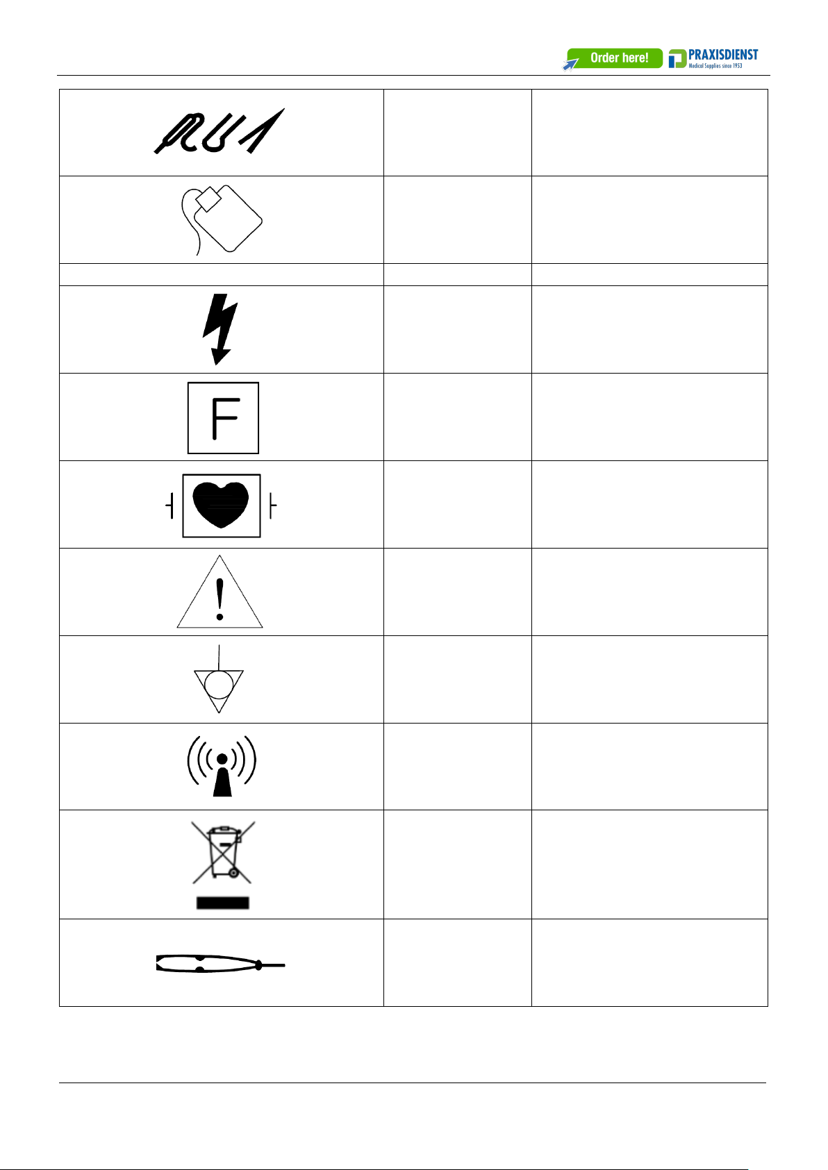
2.11 Figures and symbols
Figures and symbols
Description
Application
Dangerous voltage
External marking
Symbol for patients
whose circuits are
of high frequency
insulation
External marking
CF applied
part/defibrillation-p
roof
External marking
Attention! Please
read the attached
file
External marking, package
marking
Equipotential
External marking
Non-ionizing
radiation
External marking
Recycling of waste
electronic and
electrical products
External marking
Bipolar electrode
socket
External marking
Monopolar socket
with manual switch
External marking
Product manual. Part two front panel, back panel, figures and symbols
-15 -
Monopolar socket
with multiple
modes
External marking
Return electrode
socket
External marking
Figures and symbols
Description
Application
Dangerous voltage
External marking
Symbol for patients
whose circuits are
of high frequency
insulation
External marking
CF applied
part/defibrillation-p
roof
External marking
Attention! Please
read the attached
file
External marking, package
marking
Equipotential
External marking
Non-ionizing
radiation
External marking
Recycling of waste
electronic and
electrical products
External marking
Bipolar electrode
socket
External marking
Table of contents


