16 13
Your New! PCX™ amplifier has a TC-X Crossover (Total Control X-over©) 30-
4kHz (See page 17 for crossover Detent Chart). 12dB per octave phase correlat-
ed crossover built in to provide superior system flexibility without the added
expense and installation of an outboard crossover. The speaker outputs of
your amplifier are high-pass, low-pass, or all-pass according to the HP/LP/Full
switch on the front endplate. You would choose low pass (switch middle) to use
this amp for subwoofers, choose high pass (switch left), or full (switch right) to use
this amp for full range speakers.
The RCAoutputs are controlled by a separate HP/LP/Full switch, and are always
independent of the speaker output crossover. As well as being able to independently
select HP/LP/Full, your new PCX™ amplifier allows independent selection of
frequencies from 30-4kHz (See page 17).
NOTE: The System Diagrams beginning on page 15 show several ways to use
the virtually unlimited PCX™ amplifiers internal crossovers in your system.
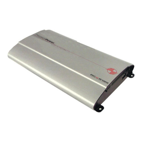
PCX 440/480/4125
Front - 12dB/Octave, Detented High Pass 30-4kHz
Rear - 12dB/Octave Detented; 30-4kHz; HP/LP/Full
RCAOutputs - 12dB/Octave Detented; 30-4kHz; HP/LP/Full
QBASS PLUS - on Rear Channel - up to 18db @ 30, 36, 44, 60Hz.
PCX 5800
Front - 12dB/Octave, Detented High Pass 30-4kHz
Rear - 12dB/Octave Detented; 30-4kHz; HP/LP/Full
RCA Outputs - 12dB/Octave Detented; 30-4kHz; HP/LP/Full
Sub-Summed Stereo 12dB/Octave Detented; 30-4kHz; HP/LP/Full
QBASS PLUS - on Sub Channel - up to 18db @ 30, 36, 44, 60Hz.
PCX 5800
1. QBASS 1 & QBASS 2 Freq.: Use these switches, QBASS 1 & QBASS 2 to program the QBASS
PLUS circuit frequency.
2. Front Inputs: Plug in the front RCAleads from your source unit here.
3. Rear Inputs: Plug in the rear RCAleads from your source unit here.
4. Sub Input: Plug in the front RCAleads from your source unit here.
5. -12dB: Push this switch ‘IN’ for high voltage input (4V-12V) capability. This button pushed ‘IN’ must be
used for speaker level input on common ground head-units or for high voltage line drivers.
6. Front Speaker/Remote Connector: Plug in the PowerLock™ connector here.
7. Rear Speaker Connector: Plug in the PowerLock™ connector here.
8. Sub Speaker Connector: Plug in the PowerLock™ connector here.
9. Front Gain: Use this control to match the output level of the source unit to the front channel of the
amplifier.
10. Front Freq. Control: Move this detented control in a clockwise rotation to adjust the front
crossover frequency from 30Hz to 4kHz.
11. Front HP/LP/FULL Switch: Select the desired crossover setting, HP/LP/FULLfor the speaker
output signal of the front channel.
12. Rear Source INT/EXT Button: Select the in, ‘INT’position if you want to use the internal signal
path from the front crossover for the rear input, or the out, ‘EXT’position to use the external rear RCA
input.
13. Rear Gain: Use this control to match the output level of the head unit to the rear channel of the
amplifier.
14. Rear Freq. Control: Move this detented control in a clockwise rotation to adjust the rear
crossover frequency from 30Hz to 4kHz.
15. Rear HP/LP/FULLSwitch: Select the desired crossover setting, HP/LP/FULLfor the internal out-
put signal of the rear channel.
16. Sub Source Int/Ext Switch: Select ‘INT’position if you want to use the internal signal path from
the rear crossover for the sub input, or the ‘EXT’position to use the external sub RCAinput.
17. Sub Gain: Use this control to match the output level of the head unit to the sub channel of the
amplifier.
18. Sub Freq. Control: Use this to adjust the rear high pass crossover frequency from 30Hz to 4kHz.
19. Sub HP/LP/FULL Switch: Select the desired crossover setting, HP/LP/FULLfor the internal output
signal of the sub channel to the speaker output.
20. Cooling Plenums: Maintain a minimum 2” clearance around cooling plenums for proper amplifi-
er cooling.
1
234567820
910 11 12 13 14 15 16 17 18 19
