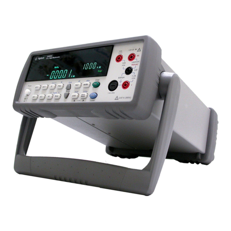
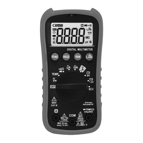
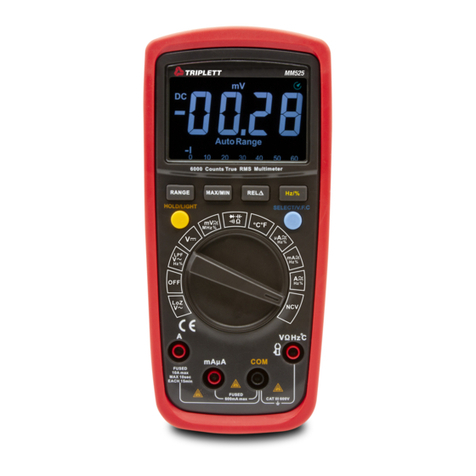
Precision 283 User manual

DYNASCAN
CORPORATION
1801WestBellePlaineAvenue,Chicago,
Illinois
60613
INSTRUCTION
MANUAL If^PRECISION
283
Hi
Ml
31/2-DiGiT
DIGITALMULTIMETER
IfCPRECISION
Productof
DYNASCANCORPORATION
1801WestBellePlaineAvenue,Chicago,Illinois
60613
STEAM POWERED RADIO.COM

INSTRUCTION
MANUAL
FOR
Model
283
31^-DIGIT
DIGITAL
MULTIMETER
DYNASCAN
CORPORAT/ON
1801WestBellePlaineAvenue
Chicago,
Illinois
60613
STEAM POWERED RADIO.COM

TABLE
OF
CONTENTS
PAGE
INTRODUCTION
3
SPECIFICATIONS
4
CONTROLS
AND
FEATURES9
OPERATION
PreparationandCheck11
Interpretation
of
Digital
DisplayReadings12
DC
VoltageMeasurements13
AC
VoltageMeasurements13
Resistance
Measurements
Out-of-Circuit
14
In-Circuit
14
Out-of-Circuit
Semiconductor
Tests
14
DC
CurrentMeasurements15
AC
CurrentMeasurements16
BATTERY
PACK
BP-83ACCESSORY17
1
OOV
and234V
LINE
OPERATION
19
THEORY
OF
OPERATION
20
Block
Diagram21
CALIBRATION
PROCEDURE22
FUSE
REPLACEMENT
23
WARRANTY
SERVICE
INSTRUCTIONS
24
ONE
YEAR
LIMITED
WARRANTY
Cov.3
INTRODUCTION
TheB & K-Precision
Model
283
Digital
Multimeter
isa significantcontribution
to
theinstrumentationmarket.Lowcostand
high
performance
have
been
engineeredintothisinstrumenttomakeavailabletotheengineer,technician,
maintenanceandservicepersonnel,andtraininginstitutionsa
digital
multimeter
thatiscompetitivelypriced
with
existinganalog
meters
and
which,
atthe
same
time,
exceeds
theperformanceof
these
meters.Inaddition,the
basic
instrument
has
been
designedformaximum
simplicity
ofoperationand
minimum
errorof
reading.
The
basic
designfeaturesofthisinstrumentmakeitanidealreplacementfor
existing
multimetersand
FET/VOM's.
Theinstrument
measures
DCandAC
voltage,
currentandohms.Ithas
high
inputimpedance(10megohms)onallvoltage
ranges,
anda wide
resistance
measurement
range
(100ohms
full
range
to10
megohms
full
range),
with
100%overrange.Inadditionto
providing
equivalent
functions
and
ranges,
theinherentaccuracyofthisinstrumentprovidesasignificant
margin
of
improved
performanceoveranalogmultimeters.
A
selectable
High/Low
Ohmsfeature,generallynotavailableon
digital
multimeters,
permitsmaking
in-circuit
resistance
measurements
atvoltagelevels
below
theconductionthresholdofsemiconductors.
Theoverloadprotectionsystemwasdesignedtoprovidemaximumprotection
of
theinstrument
with
minimum
user
inconvenience,intheeventofextreme
overload
accidents.
A
batterypackoptionisavailable
which
makes
the
Model
283completely
portableandisolated.Thepackmountsinsidethe
meter's
case,
requiring
only
a
screwdriver
for
installation.
Thisoptionprovidesmorethan8 hours'continuoususe
beforeanovernightrechargeis
needed
and
unlimited
use
while
pluggedintoanAC
line.
3
STEAM POWERED RADIO.COM

SPECIFICATIONS
DC
VOLTAGE
Ranges
Overrange
Maximum
DCInput
Accuracy
Input
Impedance
Polarity
Indication
OverrangeIndication
Circuit
Protection,
All
Voltage
Ranges
±0-1.000,
10.00,100.0,
lOOOV.
100percentto
±1.999,
19.99,199.9,1500V.
1500voltsDC,orDC+ AC
peak.
±.5
percentofreading,±1
digit,
1,10,
lOOV
range.
±1.0
percentofreading,±1
digit,
lOOOV
range.
10megohms.
Automatic;
minussignshown,plussign
implied.
If
theinputvoltage
exceeds
200percentof
full
range,
thetopandbottom
segments
onthe
first
digit
will
flash
while
thedisplay
reads
"000"(=
•••).
The
polarity
ofoverrangeisindicated.
±1500
VDC
or1500
VDC
+ AC
peak.
AC
VOLTAGE
(Averagereading
circuitry
calibratedtoreadRMSvalueofpuresinewave.)
Ranges
Overrange
Maximum
ACInput
Accuracy
0-1.000,10.00,100.0,
lOOOV
RMS.
100percent,to
1.999,
19.99,199.9,
lOOOV
RMS.
lOOOV
RMSor1500V
peak.
±1
percentofreading,±1
digit,
1,10,
lOOV
ranges.
±1.5
percentofreading,±1
digit,
1000Vrange.
4
Frequency
Response
Input
Impedance
±1
percentaccuracy:40Hzto400Hzon1,10and
lOOV
range.
±1.5
percentaccuracy:40Hzto400Hzon
lOOOV
range.
10megohms.
OverrangeIndication
Circuit
Protection,
All
Voltage
Ranges
If
theinputvoltage
exceeds
200percentof
full
range,
thetopandbottom
segments
ofthe
first
digit
will
flash
while
thedisplay
reads
"000"{-
•••).
lOOOV
RMSor1500
VDC
+ AC
peak.
DC
CURRENT
Ranges
Voltage
Drop(Measured
atInstrumentTerminals)
Overrange
Accuracy
Polarity
Indication
OverrangeIndication
Circuit
Protection,
All
Ranges
O-I.OOO,
10.00,100.0,1000mA.
250mV
(650mVon1000mArange)maximum.
100percent,to1.999,19.99,199.9and1999mA.
±1
percentofreading,±1
digit,
1,10,and100mA
range.
±1.5
percentofreading,
±1
digit,
1000mArange.
If
a DCcurrentofnegativepolarityisappliedtothe
input,
theminussign
will
light.
Theplussignis
implied.
If
theinputcurrent
exceeds
200percentof
full
range,
thetopandbottomsigmentsofthe
first
digit
will
flash
whUethedisplay
reads
"000"(=
•••).
The
polarity
ofoverrangeisindicated.
Fuse
anddiodes.
Fuse
externally
accessible
at
front
panel.
5
STEAM POWERED RADIO.COM

AC
CURRENT
Ranges
0-1.000,10.00,100.0,1000mA.
Voltage
Drop(Measured
atInstrumentTerminals)250mVRMS(650mVRMSon1000mArange)
maximum.
Overrange
Accuracy
Frequency
Response
Overrange
Indication
100percent,to
1.999,
19.99,199.9and1999mA.
±1.5
percentofreading,±1
digit,
1,10and100mA
range.
±2
percentofreading,
±1
digit,
1000mArange.
40Hzto400Hzatstatedaccuracy.
If
theinputcurrent
exceeds
200percentof
full
range,
thetopandbottom
segments
ofthe
first
digit
will
flash
while
thedisplay
reads
"000"(=
•••).
Circuit
Protection,
All
Ranges
Fuse
anddiodes.
Fuse
externallyaccessibleat
front
panel.
RESISTANCE
Ranges
0-lOO.Oohms;1.000,10.00,100.0,1000kohms;10.00
megohms.
Overrange100percent,to199.9ohms;
1.999,
19.99,199.9,
1999k
ohms;19.99megohms.
Accuracy
±1percentofreading,±1
digit,
Ikohmto1000k
ohm
ranges,
in
HIGH
ohms
function.
±2
percentofreading,±1
digit,
10megohmsrange,
HIGH
ohms
function
and100ohmto1000kohmrange,
LOW
ohms
function.
Maximum
TestCurrents100f21mA
lkS2
1mA
lOkfi
lOOpA
lOOkO
lOqA
lOOOkO
1/rA
10Mf2
lOOnA
6
Polarity
VOLTS/OHMS
(red)jackispositiveforall
ranges.
Maximum
Open
Circuit
Voltage
Voltage
with
Full
ScaleReading
Circuit
Protection,
All
Ranges
GENERAL
Operating
Temperature
StatedAccuracy
MeasuredAt
TemperatureCoefficients
PowerSource
PowerConsumption
Line
Cord
Sampling
Rate
Settling
Time,
All
Ranges
& Functions
8
volts.
0.2
volt
in
LOW
ohms.
2
voltsin
HIGH
ohms.
-500V
to+1000
VDC
+
AC
peak,continuous.
Will
withstandmomentaryoverloadsto
±1000
VDC
+
ACpeak
with
nocomponent
failure.
15°Cto35°C.
25°C±1°C.
±0.025%/°C
onDC
Volts.
±0.05%/°C
allotherfunctions.
117VAC50/60Hzfactory
wired
(usermay
change
to
lOOV
or234Vby
moving
internaltransformer
tap).
7wattsmax.;12wattsmax.ifalsochargingbattery.
3-wire,
detachable.
3readingspersecond.
Lessthanonesecond.
7
STEAM POWERED RADIO.COM

AccessoriesIncluded
Optional
Dimensions
Weight
Two
test
leads.
BP-83
Rechargeable
Battery
Pack.
PR-21Isolation/Direct
Probe
(aidsDC
measurements
in
presence
ofRF).
PR-23
RFDetector/DemodulatorProbe,15kHzto
250
MHz.
PR-28High-VoltageProbe.
LC-83
Carrying
Case.
3-5/8"
X
7"
X
9",excludinghandleand
tilt
stand.
6lbs.
8
CONTROLS
AND
FEATURES
(See
Fig.
1)
FUNCTION
SWITCH.
Selects
thetypeof
measurement
tobeperformed.Also
used
to
turntheinstrumentONandOFF.
ZERO
ADJUSTMENT.
Usedtozerothedisplay
with
the
test
leads
shortedonany
range
orfunction.
Precise
zeroindicatedbyflashingminus(-)signinDCVorDCA.
RANGE
SWITCH.
Selects
thedesired
range
forthe
measurement
selectedbythe
FUNCTION
switch.
POSITIVE
(VOLTS/OHMS)
TEST
LEAD
JACK.
"Hot"inputjack.Involtage
measurements
the
test
leadconnectedtothisjackisnormallyappliedtothe
potential
pointinthe
circuit
mostremoved
from
signalgroundorearthground.
NEGATIVE
TEST
LEAD
JACK.
Commonconnectiontotheinstrumentinput;it
shouldbeconnectedtogroundora lowimpedancepointwhenmeasuringvoltage.
Thejackdoublesasthe
2A-3AG
fuseholder.
CURRENT
(mA)
TEST
LEAD
JACK.
Thisjackis
used
whenmeasuringDCandAC
currents.
MINUS
SIGN.
A minus(-)indication
will
bedisplayedonDC
Volts
orDCCurrent
for
a negativevoltageorcurrentrespectively.
NOTE:
Thepositive(+)signis
implied
andisnotdisplayed.
NUMERICAL
READOUTS.
314-digitdisplay.Firstdisplayindicatesminussignand
1;
last
three
displaysindicatenumerals
from
"0"to"9".
HANDLE.
Forcarryingtheinstrument.
TILT
STAND.
Canbe
used
to
raise
front
ofthe283forconvenient
viewing
angle.
9
STEAM POWERED RADIO.COM

10
OPERATION
PREPARATION
AND
CHECK
a.Hugthered
test
leadintothe
VOLTS/OHMS
jack,andtheblack
test
lead
into
theblackjack.
b.
Turn
unit
onbysettingthe
FUNCTION
switchto
HIGH
S2andthe
RANGE
switchto
lOkJl.
c.
Without
a
resistance
connected
across
the
test
leads,theoverrange
indicating
shouldoccur,andshortingthe
test
leads
shouldproducea zero
reading.CheckZEROadjustment.
d.
Return
FUNCTION
switchtoACVorDCVand
RANGE
switchto
lOOOV.
Itisgoodpracticetoleavetheinstrumentinthispositionwhen
not
inusetopreventaccidentaloverloads.
SAFETY
PRECAUTIONS
A
certainamountof
danger
isalways
present
when
working
on
electrical
equipment,andtherefore,the
user
iscautionedtoalways
familiarize
himself
asmuchaspossible
with
theequipmenttobetested,
beforeany
work
isperformed.Itshouldbekeptin
mind
that
high
voltagesoften
appear
atunexpectedpointsindefectiveequipment.
When
testing
high
voltagecircuits,developthehabitofkeepingone
handinyourpockettominimizethehazardofaccidentalshock.Itis
alsoimportantto
have
a properlyinsulated
floor
or
floor
coveringto
standon
while
taking
measurements.
Beparticularlycarefultoavoid
contact
with
nearbyobjects
which
couldprovidea groundreturnpath.
It
isgoodpracticetoremove operating power beforeconnecting
test
leads.Anisolationtransformeralwaysshouldbeusedinequipment
having
the
chassis
tied
toonesideoftheACpower
line.
11
STEAM POWERED RADIO.COM

Table1
INTERPRETATION
OF
DIGITAL
DISPLAYREADINGS
SET SET
DISPLAY
TO
FUNCTION
RANGE
FULL
READINGS
RESOLU-
MEASURE
SWITCH SWITCH
SCALE
AREIN:
TION
t
DCVOLTS
0-2V
DCV IV
1.999
Volts
ImV
0-20V
lOV
19.99
Volts
lOmV
0-200V
lOOV
199.9
Volts
O.IV
0-1500V
lOOOV
1500*
Volts
l.OV
AC
VOLTS
0-2V
ACV IV 1
999
Volts
ImV
X
ill
V
0-20V
lOV
19.99
Volts
lOmV
0-200V
lOOV
199.9
Volts
O.IV
0-lOOOV
lOOOV
1000**
Volts
l.OV
CURRENT
0-2m
A
DCA 1mA m
A
11I
A
0-20mA 10mA 19.99
mA
lOqA
0-200mA 100mA 199.9
mA
100/zA
0-2Amp 1000mA 1999
mA 1mA
AC
CURRENT
0-2mA
ACA 1mA
1.999
mA liiA
0-20mA 10mA 19.99
mA
lOjuA
0-200mA 100mA 199.9
mA
lOOqA
0-2Amp 1000mA 1999
mA 1mA
OHMS
0-200f2 OHMS
100S2
199.9
Ohms
o.m
0-2000f2
(HIGH
or
LOW)
ikn 1.999
Kilohms
0-20kf2
10kf2
19.99
Kilohms
ion
0-200kn
100kf2
199.9
Kilohms
loon
0-2Mn
lOOOkfl
1999
Kilohms
ikn
0-20Mf2
lOMfi
19.99
Megohms
lokn
NOTES
*Donot
exceed
input
levels
of1500VDCorDC+ AC
peak.
**Donot
exceed
input
levels
of1000VRMSor1500V
peak.
12
t
Resolution
indicates
the
change
inthe
measured
value
that
isrequiredtoshiftthe
least
significant(right
hand)
digit,one
count.
TABLE
1 isprovidedasanaidtooperationoftheModel283and,inaddition,
provides
interpretationofthe
displays
obtained.Note
that
thedecimallocation
changes
with
thepositionoftheRANGEswitch.Thesignificanceofthedecimal
location
must
beknownto
assure
proper
interpretationofthe
readings
obtained.
2.DC
VOLTAGE
MEASUREMENTS
a.SetFUNCTIONswitchtotheDCVposition.
b.
Short
the
test
leads
and
zero
theinstrumentbyturningtheZEROcontrol
until
theMINUSsignjustlightsorflickers
with
a
zero
reading
displayed.
c.SetRANGEswitchasrequiredforthevoltageamplitudetobe
measured.
If
the
magnitude
ofthevoltageisnotknown,settheRANGEswitchto
thelOOOVpositionand
reduce
the
settings
asrequiredtoobtaina
satisfactory
reading.
d.Ifthevoltage
exceeds
that
ofthe
range
selected,
the
overrange
indication
will
operate
andflash.
Select
a highervoltage
range.
3.AC
VOLTAGE
MEASUREMENTS
a.
Place
theFUNCTIONswitchintheACVposition.
b.
SettheRANGEswitchtothe
desired
voltage
range.
Ifthevoltage
exceeds
that
ofthe
range
selected,
the
overrange
indication
will
operate
andflash.
Select
a highervoltage
range.
4.
RESISTANCEMEASUREMENTS
CAUTION
Donot
attempt
to
measure
resistance
ina circuitinwhichthe
powerapplied.
Remove
thepowerand
make
sure
that
all
capacitors
are
discharged
before
attemptingin-circuit
resistance
measurements.
13
STEAM POWERED RADIO.COM

OUT-OF-CIRCUIT:
(1)
Setthe
FUNCTION
switch
tothe
HIGH
f2position.
(2)
Setthe
RANGE
switchtothedesiredposition.
(3)
Ifthe
resistance
valuebeingmeasured
exceeds
thevalueofthe
range
selected,theoverrange
circuitry
isenergizedand
will
flash.Selecta
higherrange.
IN-CIRCUIT:
(1)
The
Model
283hasselectableLOWand
HIGH
ohms
ranges.
Conventional
resistance
measurements
canbeperformedonall
ranges.
TheLOWohmspositions
limit
themaximum
test
voltagedeveloped
across
themeasured
resistance
to0.2
volt
with
a
full
scale
reading.
This
lowvoltagepermits
accurate
measurements
of
in-circuit
re-
sistances
shuntedbysemiconductorjunctions.
Theapplied
test
voltageisproportionaltothe
resistance
reading
observed,varying
from
zero
with
the
test
leads
shortedto.2
volt
fora
full
scale
reading.Forexample,inthe100f2
range
with
a
resistance
readingof50.0ohms,thevoltagedeveloped
across
the
resistance
under
test
is.05
volt.
When
usingthe
HIGH
ohmspositions,a full-scalevoltageof2 voltsis
developed
across
themeasured
resistance.
Again,
thevoltagede-
veloped
across
themeasured
resistance
isproportionaltothe
resistance
readingobserved.Reversingthe
leads
will
resultinthe
same
reading
(within
1%)ifthereisnoshuntingbya semiconductor,andis
agoodquickcheckthattheaccuracyofthemeasurementisnotbeing
affected
bysemiconductors.
OUT-OF-CIRCUIT
SEMICONDUCTOR
TESTS:
In
additiontoconventional
resistance
measurements,
the
HIGH
ohms
ranges
canbeusedto
verify
thata semiconductor
junction
isgoodby
checking
thefront-to-backratio.
(1)
SelecttheIkf2range.
(2)
Removedevice
from
circuit.
(3)
Connectthe
test
leads
tothedevice(e.g.:diode,base-emitteror
base-coUectorjunction)andthen
reverse
theleadconnections.
Observethemeterreadingforbothconditions.
14
TEST
RESULT
CONDITION
(a)Overrange,bothpolarities
Junction
Open
(b)
ZeroorLowReading,both
polarities
Junction
Shorted
(c)
Overrangeinonedirectionand
In-RangeReadingintheother
Junction
Probably
Good
(4)
Thein-rangereadingof
Step
(c)canbeusedtodeterminewhetherthe
deviceunder
test
is
silicon
orgermanium.A readingof400to700
indicatesthedeviceis
silicon.
Anindicationof100to300indicates
thedeviceisgermanium.
(5)
The
"I-V"
curveofthedevicemaybedrawnusingthe
accurate
current
sources
ofthe283.
With
the
FUNCTION
switchsetto
HIGH
S2,
notethereadingfor
each
positionofthe
RANGE
switch,
lkf2
through
lOMfl.
Disregardingthedecimalpointlocation,
each
readingisnumericallythevoltageinmV
across
thedevice
junction
with
thecurrentthroughitlistedas
Maximum
TestCurrentin
specificationssection.
DC
CURRENT
MEASUREMENTS
a.
Place
the
FUNCTION
switchintheDCAposition.
b.
Place
the
RANGE
switchinthedesiredcurrent
range
position.Alwaysset
the
RANGE
switchtothe1000mApositionifthemagnitudeofcurrentto
bemeasuredisnotknown.
c.Connecttheplus(+)
test
leadtothecurrent
("mA")
test
leadjack.
CAUTION
Use
care
inmakingcurrent
measurements.
Make
sure
thatthemeterisconnected
in-series
with
the
loadsin
which
thecurrentistobemeasured.Never
connectthemeter
across
a voltage
source
with
the
FUNCTION
switchsetforcurrent.
Doing
somay
either
blow
theoverloadprotectionfuseor
damage
theequipmentunder
test.
When
connectingthemultimetertoreadcurrent,
first
removepowerto
the
circuit.
The
following
rules
will
insurethatthepropercurrentpolarity
is
indicated.
15
STEAM POWERED RADIO.COM

(1)
Wheninsertingthemultimeterbetweenthepositivesideofthepower
source
andtheload,connectthepositiveleadtothepower
source
and
thenegativeleadtotheload.
(2)
Wheninsertingthemultimeterbetweenthenegativesideofpower
source
andtheload,connectthenegativeleadtothepower
source
andthepositiveleadtotheload.
d.
Apply
powerandreadcurrent.
e.Ifthepolarityofthecurrentbeing
measured
isnegative,thepolarity
sensing
circuit
will
beenergized,andthevaluedisplayed
will
bepreceded
by
a minus(-)sign.
f.
Ifthemagnitudeofthecurrentbeing
measured
exceeds
thatindicatedon
the
RANGE
switch,theoverrange
circuitry
will
operate.
Whenthisoccurs,
immediately
removepower
from
the
circuit
under
test
and
select
a higher
current
range
beforeproceedingfurther.
NOTE
Current
ranges
arefuseprotected.Ifinoperative,refertoFUSE
REPLACEMENT
section.
AC
CURRENT
MEASUREMENTS
a.Setthe
FUNCTION
switchtothe
ACA
position.
b.
Setthe
RANGE
switchtothedesiredposition.Ifindoubtaboutthe
magnitudeofthe.currenttobe
measured,
usethehighestcurrent
range
andthenadjustthe
RANGE
switchasrequiredtoobtaina satisfactory
reading.
c.Connecttheplus(+)
test
leadtothecurrent
("mA")
test
leadjack.
d.
Whenconnectingthemultimeterforcurrent
measurements
removethe
power
from
the
circuit
being
tested
while
theconnectionsarebeing
made.
Reapplythepowerandreadcurrent.
e.Ifthemagnitudeofthecurrentbeing
measured
exceeds
the
range
selected,
theoverrange
circuitry
will
operate.
Whenthisoccurs,immediatelyremove
power
from
the
circuit
under
test
and
select
a highercurrent
range
before
proceedingfurther.
NOTE
Current
ranges
arefuse-protected.Ifinoperative,refertoFUSE
REPLACEMENT
section.
16
BATTERY
PACK
BP-83
ACCESSORY
INSTALLATION
(Referto
Fig.
2)
1.
With
theModel283unplugged,removethetwo
screws
onthebackthatfasten
thecover.
Lift
the
rear
ofthecover,
slightly
andslideitforwardto
expose
the
insideoftheinstrument.
2.
Thereisa pairofblackplasticconnectors
near
thetransformer
which
join
the
transformerwirestothemain
circuit
board.Carefully
pull
theconnectors
apart,
holdingthembytheshells,notbythewires.
3.
Place
theBP-83assemblyinthe
space
near
thetransformer,
with
thebattery
againstthe
rear
ofthe
chassis.
Locatethebatterysothattheterminalpolarity
isasshowninFig.2.Slidetheassemblyback,sothatthehookedtabofthe
bracket
fits
throughtheslotatthe
rear
ofthe
chassis
andpushitdown.
4.
Insertthetwo
screws
suppliedthroughthebottomofthe
chassis
intothe
BP-83bracketandtightenthemsnugly.
Fig.
2.Internalview.
17
STEAM POWERED RADIO.COM

5.Connectthetwoplasticconnectorsof
step
2 tothecorrespondingconnectors
of
theBP-83(theyonlyfitoneway- donotforce).
6.CheckpolaritystampedonbatteryagainstFig.2,thenconnecttheshortred
(+)
andblack(-)wirestothebatteryterminals.
Replace
cover.
OPERATION
WhenevertheinstrumentispluggedintoanACoutlet,thebatteryisbeing
charged.Thecharging
rate
varies
with
thebattery's
state
of
charge
toprevent
overcharging.Whenoperatingaway
from
ACpower,theunitmaybe
used
continuouslyformorethaneighthoursbeforethedisplaydimsandanovernight
recharge
is
needed.
Themetercanbe
used
while
recharging,althoughthislengthens
the
charge
timerequired.
18
lOOV
and234V
LINE
OPERATION
(RefertoFig.2)
TheModel283isfactory-connectedforuse
with
117V,50/60HzAClines.To
operate
iton
lOOV
or234V50/60Hzpower,aninternalconnectionmustbe
moved, as
follows:
With
theunitunplugged,removethetwo
screws
onthebackthatfastenthe
cover,
lift
the
rear
ofthecover
slightly
andslideitforwardto
expose
theinside
of
theinstrument.Locatethetransformerand
lift
thewhitewireoffits
center
"quick-disconnect"terminal.Thismustbemovedtooneofthetwoother
terminalsasshowninFig.2.
If
theunitistoberunon234Vpower,thelinefuseshouldbechanged.
Notethemannerin
which
the
original
1/8Aslow-blowfuseissolderedto
terminal
stripon
rear,
thenremoveit.
Replace
with
1/16A-250Vslow-blowfuse
supplied.Thewires
within
the
detachable
linecordarecolor-codedaccordingto
theEuropean
DIN
standard.
19
STEAM POWERED RADIO.COM

THEORY
OFOPERATION
(Referto
Block
Diagram,Fig.3)
TheModel283
operates
byconvertingthevarioustypesofinputsignalsintoa
scaledDCvoltage
which
isthentransformedinto
digital
informationbythe
integratorandlogiccircuits.
Voltage
inputsareappliedthroughtheattenuator(resistornetworkRNl)toa
high
impedancevoltage
follower
(ICl)fora 2
volt
full
scale
swing.ACvoltagesare
thenfull-waverectified,
filtered,
andscaledtoproducea DCvoltageequaltothe
RMS
valueofa sinewave.
Resistance
measurements
are
made
bygeneratinga precisionconstantcurrent
(controlled
by1C4)
which
developsa DCvoltage
across
the
measured
resistor
proportional
toits
resistance.
Thesignalisthenappliedtothe
follower
and
processed
asforvoltage
measurements
with
theexceptionthat,when
LOW
f2is
selected,thecurrent
source
isdividedby10andthegainofthevoltage
follower
is
switched
from
xltoxlO,toprovidea
full
scale
swing
from
0.2voltsatitsinput.
The
RANGE
switchpicksthemagnitudeofthecurrent
generated
(1mAmax.).
Forcurrent
measurements,
theinputis
passed
throughoneoffoursmallshunt
resistances
todevelop0.2voltsfora
full
scale
reading.Thisvoltageisappliedtothe
voltage
follower
initsgainof10mode.
Theoutputofthevoltage
follower
(orofthe
AC-to-DC
converter)isconverted
to
digital
formatbythedual-slopeintegrator(1C2C)andthe
L.S.I,
logicchip(1C6).
The2
references
used
fortheintegrationarederived
from
a
highly
stable
zener
(Dl
1)
with
fixed
currentdrive.
20
STEAM POWERED RADIO.COM

MODEL
283
CALIBRATIONPROCEDURE
(Referto
Fig.
2 forLocationofInternalAdjustments)
Theinstrumentshouldnotrequirecalibration
unless
repairs
have
been
made
that
change
thefactorycalibration.Priortocalibration,theinstrumentshouldbe
checkedforproperoperationofallfunctionsandfor
damage
from
physical
abuse
orunprotectedoverloads.
The
following
procedureshouldbeperformed
with
lowimpedanceconstant
voltage
sources
of0.1%accuracyorbetter.Useof
sources
with
less
accuracy
reduces
theaccuracyoftheinstrument.
Thecalibrationisperformed
with
thetopcoverremoved.Toremovethetop
cover
from
theunit,thetwo
screws
holdingthecovermustberemoved.Then
lift
thebackofthecoverup
slightly
andforwardtoclearthe
tabs
onthe
front
panel.
EQUIPMENT
REQUIRED.
DCV
meter,
0.1
mVresolution.
1.5V
±0.1%
voltagesource.
1.5kS2
±0.1%
resistor.
PROCEDURE
(These
steps
mustbeperformedinorderlisted):
1.
Cormectvoltmeterbetweenthewire"T.P."andcommoninputjack.
2.
Setunitto
DCV,
IVrange,
with
inputsshorted.
3.Adjust
front
panelZEROfora
measurement
of0
±0.1mV
atT.P.Disconnect
voltmeter
from
unit.
4.
Adjust
A/D
trimpotfordisplayof.000
with
minussignflashing.
5.Removeshort
from
inputandapply+1.500VDC;adjust+Vpotforthis
reading.
6.
Apply
-1.500
VDC;
adjust-Vpotforthisreading.
7.Removevoltage
source
andshorttheinputs.
8.Set
FUNCTION
toACV.RotateACpotclockwise
until
a displayof
1
or2mV
isobserved,thenbackoffcounterclockwisejustenoughtoachievea
steady
zero.
22
9.Set
FUNCTION
to
HIGH
f2andconnectreferenceresistortoinputs.Adjust J2
potforcorrectreading.
10.
Closecover.
FUSEREPLACEMENT
Thenegativejackis
also
a fuseholder.Toreplacefuse,pushinandturnthe
insertcounterclockwisetoremovethefuse.Replace only with the proper
2A-3AG
type fuse. To
re-assemble,
insertnewfuse,pushinandturntheinsertclockwiseto
theinternalstop.
23
STEAM POWERED RADIO.COM

i
1
!
i
1
1
T
'
f
1
T
i
1 1
f
i
T
1
f
r
DS-3
DS-4
T
STEAM POWERED RADIO.COM

B
&
K-PRECISION
MODEL
283
PARTS
LIST
488-16309-002-B
SCHEMATIC
B & K
SYMBOL
DESCRIPTION
PART
NUMBER
RESISTORS
R25
0.098n,'AW,
Vi%
Wirewound
004-125-9-001
R260.9f2,
lW,iA%
Wire
wound
004-160-9-001
R279S2,
>AW,
'A%Metal
Film
Oil-088-9-001
R289012,
'AW,
'A%
Metal
Film
011-089-9-001
R34
470kl2,'AW,
5%MetalFilm
011-102-8474
R46100kS2,5W,10%
Metal
Glaze004-161-9-001
R47Special,
High
VoltageCurrent
Limiter,
004-163-9-001
Base
Resistance,
2kl2
±40%
R492.5kl2
Trimpot
008-236-9-001
R52100kl2
Trimpot
008-238-9-001
R53,54,
5550012
Trimpot
008-237-9-001
R568.87kl2,
'AW,
1%,
Metal
Film
011-122-9-001
R218100kl2
Multi-turn
Potentiometer008-254-9-001
CAPACITORS
CI,
2,20lOOpF,500V,10%Pre-formedCeramicDisc020-044-9-001
^^j^^^
}
-^^f^^'
100V,-20,+80%Pre-formedCeramic
Disc.
020-101-9-001
C9.OOl/uF,
IkV,
10%Pre-formedCeramicDisc020-138-9-001
CIO
.022qF,
IkV,
20%Pre-formedPolyester025-103-9-001
CI
1,12470/uF,25V
Electrolytic
022-095-9-001
C131.5/iF,
1
OOV
P.P.Polyester025-101-9-001
C14.0033/aF,
1
OOV,
20%P.F.Polyester025-105-9-001
CI
5
.047qF,
1
OOV,
10%
Polyester025-094-9-001
CI6,
17
lOjuF,
16V,20%Pre-formedTantalum027-010-9-001
C18
15mF,
lOV,
20%Pre-formedTantalum027-009-9-001
C19
220/LiF,
lOV
Electrolytic
022-109-9-001
C201
330pF,500V,10%,PinLead,CeramicDisc020-151-9-001
202
.005aiF,
500V,20%,PinLead,CeramicDisc....020-152-9-001
DIODES
Dl,2,3,4
Diode,
lA,600V
151-050-9-001
D5,6
Diode,Protection
Silicon
151-054-9-001
D7
Diode,
Silicon
Low
Leakage
151-055-9-001
D8
Diode,1N4007151-053-9-001
D9
Diode,Zener6.2V,5%,
1W(IN4735A)
152-037-9-001
DIO
Diode,Zener1N749A
(4.3V)
152-062-9-001
Dl
1
Diode,
Reference
Zener1N4565
(6.4V)
152-066-9-001
TRANSISTORS
}
Silicon
2N5818176-051-9-001
Q7,
8,9 PET,N-ChannelClampDiode182-036-9-001
QIO
PET,P-Channel182-035-9-001
INTEGRATED
CIRCUITS
1C1,1C4CA3130PETOpAmp307-073-9-001
IC2
1C324QuadOpAmp307-060-9-001
IC3
IC30lOpAmp307-074-9-001
IC5
CA3081Transistor
Array
037-075-9-001
1C6AY-5-3507307-077-9-001
1C7IC4001Quad
Gates
307-072-9-001
1C8IC4016Quad
Bilateral
Switch307-076-9-001
COMPOSITE
499-086-9-001-B
STEAM POWERED RADIO.COM

SCHEMATIC
B
81
K
SYMBOL
DESCRIPTION
PART
NUMBER
NETWORKS
RNl
Resistor
Network,
Input012-011-9-001
RN2
Resistor
Network,
Display012-007-9-001
RN3
ResistorNetwork012-008-9-001
RN4
ResistorNetwork012-009-9-001
TRANSFORMERS
AND
SWITCHES
Tl
PowerTransformer065-116-9-001
51
Switch,
Function083-186-9-001
52
Switch,
Range
083-187-9-001
DISPLAYS
DS1,2,
3,4H.P.5082-7650238-008-9-001
MISCELLANEOUS
Fl
Fuse
1/8A,3AG
Pigtail
193-011-9-001
Fl
Fuse
1/16A,
3AG
Pigtail
(240V
Wired
Unit)
193-004-9-001
F2
Fuse,
2 Amp,3AG191-251-3-002
Bracket,
P.C.Board251-157-9-001
Cover,Top253-042-9-902
Chassis,
Main
257-067-9-902
Decorative
Inlay
(SidePanel)260-063-9-001
Front
PanelOverlay260-069-9-001
Bracket,
Handle
Mounting
261-067-9-001
Case
EndPanel,
Right
271-041
-9-001
Case
EndPanel,
Left
271-042-9-001
Terminal
Strip345-013-9-001
Fuse
Housing,A (2req'd)380-247-9-001
Bezel,
Display280-250-9-001
m
Filter,
Transparentred280-251-9-001
Foot,
Front381-059-9-001
Foot,
Rear
381-061-9-001
Line
Cord420-022-9-001
TestLead,
Black
522-062-9-001
TestLead,Red522-063-9-001
Fuseholder/JackAssembly523-115-9-001
Tinnerman
(for
window)
652-042-9-001
"E"
Ring,
Bowed(forfusehousing)741-082-9-001
Handle
746-030-9-001
Knob
751-130-9-001
P.C.B.,
PlasticStandoff759-062-9-001
Spring,
Fuse
Contact767-038-9-001
Receptacle,
Chassis
AC770-018-9-001
Banana
Jack,
Red774-001-9-001
Stand,
Wire
Form804-005-9-001
NOTE:
Standard
value
resistors
arenot
listed.
Values
maybe
obtained
from
schematic
diagram.
Minimum
charge
S5.00per
invoice.
Orders
will
be
shipped
C.O.D.
unless
previous
open
account
arrangements
iiave
been
made
or
remittance
accompanies
order.
Advance
remittance
must
cover
postageorexpress
charges.
Specify
serial
number
wiien
ordering
replacement
parts.
B
&
K-PRi:aS10N
•
DYNASCAN
CORP.
• 1801W.BellePlaineAve.• Chicago,
IIL
60613
STEAM POWERED RADIO.COM

B
& K DivisionofDYNASCAN
CORPORATION
2815W,IrvingParkRd.,Chicago,Illinois60618
Phone;312/5834360
FactoryAuthorizedParts& ServiceCenters
492036
-
0
•
777
Thefollowingwillhandleanypartsand/orserviceproblems,eitherinoroutof
warranty.Yournearestservicecenterhasbeenselectedforqualityandprompt
attentiontoyourneeds.Pleasetakeadvantageofthisservicefacilityestablished
foryourbenefit.Thislistissubjecttochangewithoutnotice.Pleasecontact
servicecenterbeforeforwardingequipmentforrepair.
TEST
EQUIPMENT
ALABAMA
Arnold'sInstrumentService
2116DauphinIslandPkwy.
Mobile,AL36605
205/478-3230
ARIZONA
ArizonaCertifiedElectronics
2629N.1stAve.
Tucson,
AZ85719
602/623-2432
ArizonaElectricStandardLab
1845W.CampbellAve.
Phoenix,AZ85015
602/264-9351
ARKANSAS
ElectronicsSales& Service
7515GeyerSpringsRd.
LittleRock,AR72209
501/565-0774
CALIFORNIA
ElectronicServiceCo.
8128OrionAve.
VanNuys,CA91406
213/780-3071
GuaranteedElectronics
5822MissionSt.
SanFrancisco,CA94112
415/334-5900
TeletekEnterprises,Inc.
2749KilgoreRd.
RanchoCordova,CA95670
916/635-1331
ValleyScientific
P.O.Box7751
5510AirTerminalOr.East
Fresno,CA93727
209/291-6381
CANADA
AtlasElectronicsLimited
50WingoldAve.
Toronto,Ont.,CanadaM6B1P7
416/781-6174
COLORAOO
HouseofTVRepair
1445FlorenceSt.
Aurora,CO80010
303/366-1581
ClydeN.StillElectronics
2630W.Kiowa
ColoradoSprings,CO80904
303/633-8404
CONNECTICUT
L& L Electronics
186N.MainSt.
Branford,
CT06405
203/488-4814
DISTRICTOFCOLUMBIA
ElectronicMaintenance
308CarrollSt.N.W.
Washington,DC20012
202/882-2333
FLORIDA
AzaleaParkAppliance,Inc.
1201W.PineSt.
Orlando,FL32805
305/425-1440
EleconCorp.
398639th
St.Petersburg,FL33709
813/522-5451
IDAHO
IdahoInstrumentService
410ElmSt.N.
TwinFalls,ID83301
208/733-5636
STEAM POWERED RADIO.COM

ILLINOIS
OynascanCorp.
2815W.IrvingParkRd.
Chicago,IL 60618
312/5834360
E.I.L.
Instruments,Inc.
9708IndustrialOr.
Bridgeview,IL60455
312/430-2292
INDIANA
E.I.L.
Instruments,Inc.
7061TwinOaksDr.,SuiteM
Indianapolis,IN46226
317/545-1373
Electro-LabServices,Inc.
510WilliamsRd.
Evansville,IN47712
812/423-5211
KANSAS
MainElectronics,Inc.
225Ida
Wichita,KS67211
316/267-3581
KENTUCKY
LouisvilleMeterService
2829DellBrookeAve.
Louisville,KY40220
502/454-3432
LOUISIANA
TelcomofNewOrleans,Inc.
4239BanksSt.
NewOrleans,LA70119
504/482-8732
MARYLAND
E.I.L.
Instruments,Inc.
1830YorkRd.
Timonium,MO21093
301/252-1260
O-Tronics
1237QueenAnneAve.
Odenton,
MO21113
301/672-1127
MASSACHUSETTS
ElectricServiceCenter
39MollisSt.
E.Pepperell,MA01437
617/433-6940
MICHIGAN
ElectroInstrumentRepair
Div.InstrumentSpecialties,Inc.
1024West14MileRd.
Clawson,
Ml48017
313/435-3311
MICHIGAN(cont'd)
MainElectronics
5558S.PennsylvaniaAve.
Lansing,
Ml48910
517/882-5035
MISSOURI
LaneElectronics,Inc.
3805Chouteau
KansasCity,MO64117
816/455-0308
KermitShetleyRepair
2031WoodlandHillsOr.
CapeGirardeau,MO63701
314/334-2055
ScherrerInstruments
7170ManchesterAve.
St.Louis,MO63143
314/644-5362
NEBRASKA
Alpha-OmegaAppliedElectronics,Inc.
2208FranklinSt.
Bellevue,NE68005
402/291-2200
Bob'sIndustrialElectronics
1720N.Sherman
NorthPlatte,NE69101
308/532-8017
ElectrometricsCo.
404South11th
Lincoln,
NE68508
402/477-3434
MidwesternLaboratories
14965GroverSt.
Omaha,NE68144
402/334-5606
NEWJERSEY
HosicaLaboratories
715MainSt.
NorthCaldwell,N.J.07425
201/256-7724
NEWMEXICO
BradleyElectronics
6344Linn,N.E.
Albuquerque,NM87100
505/268-6930
NEWYORK
AltairElectronicsService,Inc.
474ThurstonRd.
Rochester,N.Y.14619
716/235-1470
STEAM POWERED RADIO.COM

NEWYORK(cont'd)
CircleTele-Tronics,Inc.
1008UticaAve.
Brooklyn,
N.Y.11203
212/345-5656
NORTHCAROLINA
MusicCenterRepairs
213EastMainSt.
Cherryville,N.C.28021
704/435-5304
SpeedInstrument
Oiv.Owen-Barbot,Inc.
Hwy.#401NorthBox11456
Raleigh,
N.C.27604
919/876^919
OHIO
E.I.L.
Instruments,Inc.
7915SouthSuburbanRd.
Oayton,
OH45459
513/435-2134
PioneerCleveland
Oiv.PioneerStandardElectronics,Inc.
4800E.131St.
Cleveland,
OH44105
216/587-3600
PioneerDaytonInstrumentLab
1900Troy
Oayton,
OH45404
513/236-9900
OKLAHOMA
Stark'sAvionics& Comm.Service
1604N.E.Woodlands
PoncaCityAirport
PoncaCity,OK74601
405/765-8264
OREGON
Westcon
1910N.KillingsworthSt.
Portland,
OR97217
503/285-6629
PENNSYLVANIA
AmericanInstrumentService,Inc.
44145N.5thSt.
Philadelphia,PA19123
215/923-6760
Oynatronics,Inc.
Route611
Tannersville,PA18372
717/629-0050
E.I.L.
Instruments,Inc.
1844Ardmore
Blvd.
Pittsburgh,PA15221
412/731-5230
RHODEISLAND
E.I.L.
Instruments,Inc.
6810PostRd.
NorthKingstown,R.I.02852
401/885-1773
SOUTHCAROLINA
King's
114S.MainSt.
Bishopville,S.C.29010
803/484-5482
TENNESSEE
InstrumentRepairService
468N.Watkins
Memphis,TN38104
901/278-0762
TEXAS
BorderElectronicsServices
1704E.Paisano
P.O.Box3804
ElPaso,TX79923
915/532-2524
CentralInstrumentLaboratory
777S.CentralExpressway
Richardson,TX75080
214/234-2862
ChampionInstrumentLaboratory
624S.TatarRoad
Pasadena,TX77506
713/473-6680
TheMeasurementsCompany
8100S.Kirkwood,Suite105
Houston,
TX77072
713/498-7478
MooreElectronicService,Inc.
3511Pinemont,SuiteA-4
Houston,
TX77018
713/682-4430
OsmondAssociates
1716E.Yandell
ElPaso,TX79902
915/542-0024
WhitlockInstrument
1306NorthTexasStreet
Odessa,TX79762
915/337-3412
UTAH
SaltLakeInstrumentsService
129W.17thSouth
SaltLakeCity,UT84115
801/487-2541
STEAM POWERED RADIO.COM

VIRGINIA
E.I.L.
Instruments,Inc.
5400CherokeeAve.
Alexandria,VA22312
703/354-4330
WASHINGTON
B&FRepair
E.15110Sprague
Veradale,WA99037
509/926-9037
Eicher-RichardsCo.
2727N.E.BlakeleySt.
Seattle,WA98105
206/523-7888
TheLectronicShoppe
202W.MainSt.
Everson,
WA98247
206/966-3621
Sutherlands,Inc.
952IndustryOr.
Building26
Tukwila,WA98188
206/575A075
WISCONSIN
Electro-MechanoCo.
241E.ErieSt.
Milwaukee,Wl53202
414/272^050
PUERTORICO
E.I.L.
Instruments,Inc.
Marginal,
A12
UrbanizationLosAngeles
Carolina,PuertoRico00630
809/791-4115
SOUTHAMERICA
TeleromanCIALTOA
10deAgosto614y Boyaca
Guayaquil,S.A.
Ecuador
513--525Casilla3906
AUSTRALIA
Parameters,PTY,LTO.
P.O.Box480
CrowsNest,
N.S.W.
Australia2065
Oynascan
Corporation—
6460
W.Cortland—
Chicago,
Illinois
60635
PrintedInU.S.A.
STEAM POWERED RADIO.COM
Table of contents
