Preferred Power Products P3POE8-30 User manual

USER MANUAL
Part Number: P3POE8-30
8 Port 10/100/1000 Base-TX 8 PoE Sw tch
INTRODUCTION
Power-over-Ethernet (PoE) eliminates the need to run DC power to other devices on a wired LAN. Using a
Power-over-Ethernet s stem, installers need to run onl a single Categor 5 Ethernet cable that carries both
power and data to each device. This allows greater flexibilit in the locating of network devices and, in man
cases, significantl decreases installation costs.
There are two s stem components in PoE: 1. The PSE (Power Sourcing Equipment) and 2. The PD (Powered
Device). The IEEE 802.3af/at specification defines PSE as a device that inserts power onto an Ethernet cable.
The PSE ma be located at the switch (Endspan configuration). or it ma be a separate device located between
the switch and the PD (Midspan configuration). The PD is the natural termination of this link, receiving the
power, and could be an IP phone, a WLAN access point, or an other IP device that requires power. The
current is transmitted over two of the four twisted pairs of wires in a Categor -5 cable.
Power-over-Ethernet follows the IEEE 802.3af/at specification and is completel compatible with existing
Ethernet switches and networked devices. Because the Power Sourcing Equipment (PSE) tests whether a
networked device is PoE-capable, power is never transmitted unless a Powered Device is at the other end of
the cable. It also continues to monitor the channel. If the Powered Device does not draw a minimum current
because it has been unplugged or ph sicall turned off, then the PSE shuts down the power to that port. The
standard permits Powered Devices to signal the PSEs as to exactl how much power the need.
The PoE switch is a multi-port fast ethernet switch that can be used to build high-performance switched
workgroup networks. This switch is a store-and-forward device that offers low latenc for high-speed
networking. It also features a “store-and-forward” switching scheme that allows the switch to auto-learn and
store source addresses in a 1K-entr MAC address table. The switch is targeted at workgroup, department or
backbone computing environments.
HARDWARE DESCRIPTION
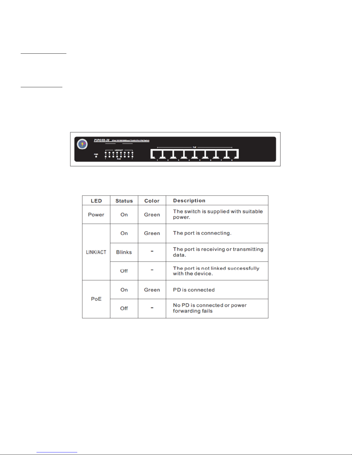
The Front Panel:
The front panel consists of LED Indicators and 8 auto-sensing ports.
LED Indicators:
Per Device: Power
Per Port: LINK/ACT (Link/Activit )
Per PoE Port: PoE
Front Panel View of LED indicators
RJ-45 Ports (Auto MDI/MDIX)
This product features Auto-sensing ports of 10/100 N-wa for 10Base-T or 100Base-TX connections. In general,
MDI means connecting to another Hub or Switch while MDIX means connecting to a workstation or PC.
Therefore, Auto MDI/MDIX means that ou can connect to another Switch or workstation without changing
pin-to-pin or crossover cabling. All of these ports can suppl to PDs.

The Rear Panel
The rear panel view of the PoE switch consists of an AC Power Connector
AC Power Connector
Plug the female connector into the switch and male connector into the power outlet. This product supports
input voltages 100 – 240 VAC, 50/60 Hz.
PACKAGE CONTENTS
PoE Switch: 8 Port 10/100/1000Base-TX with 8 Port PoE Switch
AC Power Cord
Four (4) adhesive-backed rubber feet
User’s Manual
IMPORTANT: If an piece is missing or damaged, please contact our local dealer or reseller for service.
NETWORK APPLICATION
This section provides a few examples of networked topolog which are used. PoE switch is designed as a
segment switch that has a large address table and high performance to deal with interconnecting networking
segments. PC, workstations, and servers can communicate with each other b directl connecting with the PoE
switch. The switch automaticall learns nodes addresses, which are subsequentl used to filter and forward all
traffic based on the destination address. The PoE switch can provide power to PDs that follow the IEEE
802.3af/at standard in the network and solves the problem of position limitation. The network devices can be
installed in more appropriate position for better performance. The following figure is an example of network
application for Power over Ethernet Switch.

TROUBLESHOOTING
Incorrect Connect ons
Ever port on this switch can automaticall detect either straight or crossover cables when ou link it with
other Ethernet devices but other devices ma demand a specific cable t pe depending on the device. Choose
the appropriate cable to connect between the units. The RJ-45 connector should use correct UTP or STP cable,
10/100Mbps port use 2-pairs twisted cable. If the RJ-45 connector is not correctl pinned then the link will fail.
Faulty or Loose Cables
Look for loose or fault connections. If the appear to be OK, then make sure the connections are snug. If
that does not correct problem, tr a different cable
Non-Standard Cables
Non-standard and mis-wired cables ma cause numerous network collisions and other network problems, and
can seriousl impair network performance. A cable tester is the recommended tool for an proper network
installation.
RJ-45 Ports
Use unshielded twisted-pair (UTP) or shield twisted-pair (STP) cable for
RJ-45 connections: 100Ω Categor 3, 4 or 5 cable for 10Mbps connections, 100Ω
Categor 5 cable for 100Mpbs connections, or 100Ω Categor 5e/above cable for
1000Mbps connections. Also be sure that length of an twisted-pair connection does not exceed 100 meters
(328 feet). We suggest using Categor 5e cable when connection to power a device.
Improper Network Topolog es
It is important to make sure that ou have a valid network topolog . Common topolog faults include
excessive cable length and too man repeaters (hubs) between end nodes. In addition, ou should make sure
that our network topolog contains no data path loops. Between an two ends nodes, there should be onl
one active cabling path at an time. Data path loops will cause broadcast storms that will severel impact our
network performance.
D agnos ng LED Ind cators
To assist in identif ing problems, the switch can be easil monitored through panel indicators, which describe
common problems the user ma encounter and where the user can find possible solutions. If the LED displa
detection isn’t correct, please unplug then plug in the cable again. If the power indicator does not light when
the power cord in plugged in, ou ma have a problem with the power outlet or power connections, power
losses, or surges at power outlet. If the problem still cannot be resolved, please contact the local dealer for
assistance.

PRODUCT SPECIFICATONS
Standard: IEEE802.3.10Base-T Ethernet
Compliance: IEEE802.3u 100Base-T Ethernet
IEEE802.3ab 1000Base-T Ethernet
IEEE802.3af/at Power over Ethernet
Transfer Rate: 148,800 pps for 100Mbps
1,488,000 pps for 1000Mbps
Connector: 10/100/1000TX: 8 x RJ-45 with auto MDI/MDI-X functions
PoE Pin Assignment: V+ (RJ45 Pin 3,6) V-(RJ45 Pin 1,2)
MAC Address: 8K Mac Address Table
Switching Capacit : 16G
LED Connector: Per Port: Link/Activit
Per PoE Port: PoE
Per Unit: Power
Network Cable: 2 Pair UTP Cat 5e Cable
EIA/TIA-568 100 –ohm STP (100M / 300Ft)
Dimension: 10.82”W x 7.28”D x 1.73”H
Ventilation: Built-in Noiseless Fan
Operating Temp: 32⁰F - 113⁰F (0⁰C - 45⁰C)
Operating Humidit : 10% - 90% Non-Condensing
Power Suppl : Built-in Power Suppl
Input: AC100-240VAC, 50/60 Hz
Power Consumption: 250W
EMI: FCC Class B, CE
FCC STATEMENT - This equipment has been tested and found to compl with the limits with a Class B device,
pursuant to part 15 of the FCC rules. These limits are designed to provide reasonable protection against
harmful interference in a commercial installation. This equipment generates, uses and can radiate radio
frequenc energ and if not installed and used in accordance with instructions, ma cause harmful
interference with radio communications. Operation of this equipment in a residential area is likel to cause
harmful interference, in which case, the user will be required to correct the interference at the user’s expense.
3139 MacArthur Blvd. Northbrook, IL 60062 • www.pthree.com • 877-478-4733
Table of contents


