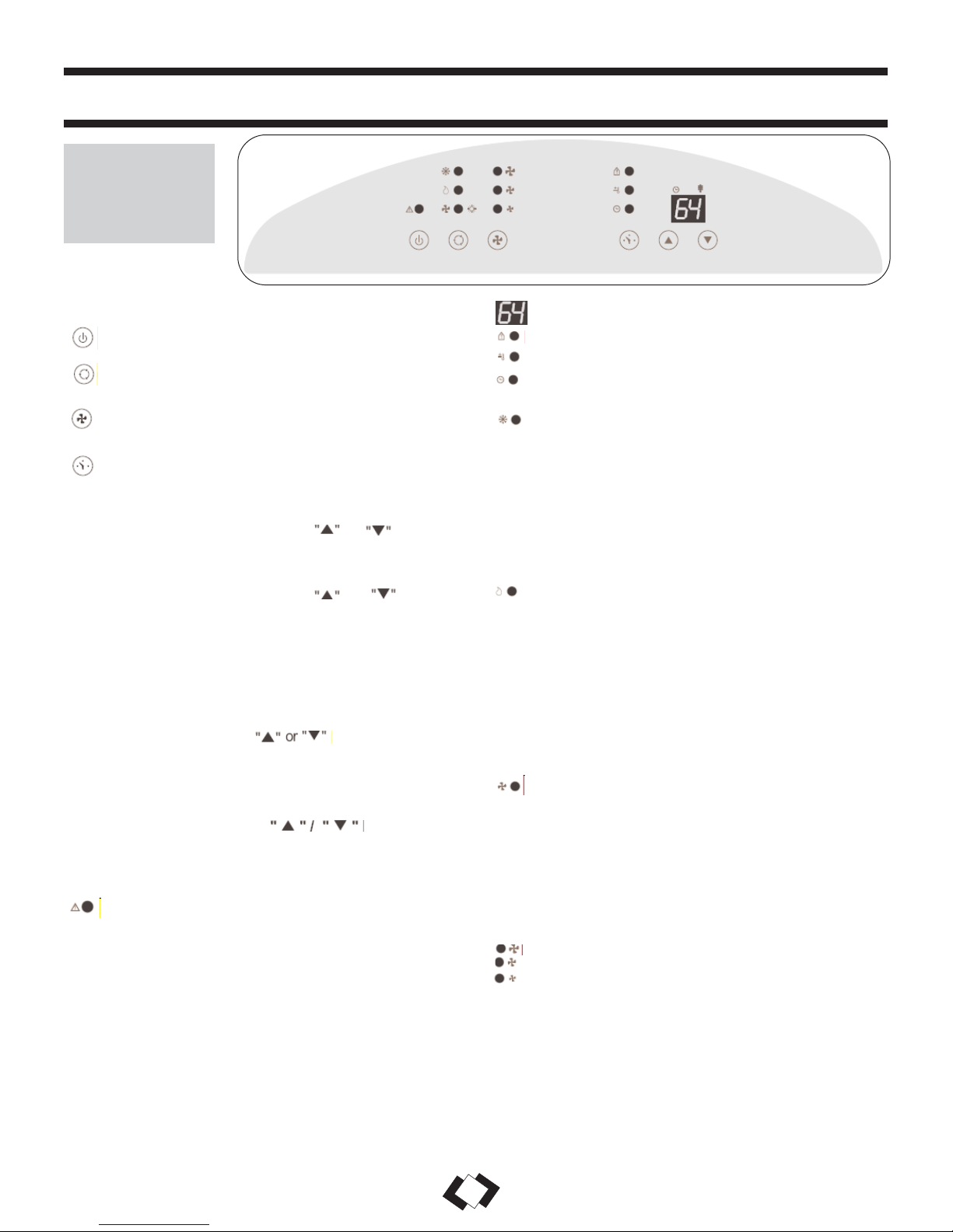
premiere Premiere DPAC 12099 Assembly instructions

Owner’s Use and Care Guide
Guide d’utilisation et soins de
Propriètaire
Model • Modèle
DPAC 12099
Danby Products Ltd, PO Box 1778, Guelph, Ontario Canada N1H 6Z9
Danby Products Inc, PO Box 669, Findlay, Ohio USA 45839-0669
Version 2.1.09 JF
KEEP THESE INSTRUCTIONS FOR FUTURE REFERENCE: If the unit changes ownership, be sure this manual
accompanies the unit.
CONSERVER CES INSTRUCTIONS POUR CONSULTATION ULTÉRIEURE: En cas de revente du l’appareil, ce manuel
doit être inclus avec l’appareil.
CAUTION: Read and
follow all safety rules
and operating
instructions before first
use of this product.
MISE EN GARDE:
Veuillez lire
attentivement les
consignes de sécurité et
les directives
d’utilisation avant
l’utilisation de ce
produit.
PORTABLE AIR CONDITIONER
Table of Contents . . . . . . . . . . . . . . . . . . . . . . . . . . . . . . . . . . . . . . . . . 1
CLIMATISEUR PORTATIF
Table des Matières . . . . . . . . . . . . . . . . . . . . . . . . . . . . . . . . . . . . . . . . 13

UNIT SPECIFICATIONS . . . . . . . . . . . . . . . . . . . . . . . . . . . . . . . . . . 2
PART IDENTIFICATION . . . . . . . . . . . . . . . . . . . . . . . . . . . . . . . . . . 3
IMPORTANT SAFETY INFORMATION
Electrical Specifications . . . . . . . . . . . . . . . . . . . . . . . . . . . . . . . . . . . . . . . 3
Energy Saving Tips . . . . . . . . . . . . . . . . . . . . . . . . . . . . . . . . . . . . . . . . . . . . . 4
INSTALLATION . . . . . . . . . . . . . . . . . . . . . . . . . . . . . . . . . . . . . . . 5
Window Kit Installation . . . . . . . . . . . . . . . . . . . . . . . . . . . . . . . . . . . . . . . 6
OPERATION
Remote Control . . . . . . . . . . . . . . . . . . . . . . . . . . . . . . . . . . . . . . . . . . . . . 7
LCD Display . . . . . . . . . . . . . . . . . . . . . . . . . . . . . . . . . . . . . . . . . . . . . . . . . . 7
Air Conditioning . . . . . . . . . . . . . . . . . . . . . . . . . . . . . . . . . . . . . . . . . . . . . 8
Dehumidifier . . . . . . . . . . . . . . . . . . . . . . . . . . . . . . . . . . . . . . . . . . . . . . . . . . 9
Fan . . . . . . . . . . . . . . . . . . . . . . . . . . . . . . . . . . . . . . . . . . . . . . . . . . . . . . . 9
Heat . . . . . . . . . . . . . . . . . . . . . . . . . . . . . . . . . . . . . . . . . . . . . . . . . . . . . . 10
Auto Timer . . . . . . . . . . . . . . . . . . . . . . . . . . . . . . . . . . . . . . . . . . . . . . . . . 11
Clock Set . . . . . . . . . . . . . . . . . . . . . . . . . . . . . . . . . . . . . . . . . . . . . . . . . 11
CARE AND MAINTENANCE . . . . . . . . . . . . . . . . . . . . . . . . . . . . 12
TROUBLESHOOTING . . . . . . . . . . . . . . . . . . . . . . . . . . . . 13
Warranty . . . . . . . . . . . . . . . . . . . . . . . . . . . . . . . . . . . . . . . . . . . . . . . . . 14
TABLE OF CONTENTS
1

Thank you for choosing a Danby appliance to provide you and your family with all of the “Home
Comfort” requirements of your home, cottage, or office. This Owner’s Use and Care Guide will
provide you with valuable information necessary for the proper care and maintenance of your new
appliance. If properly maintained, your Danby appliance will give you many years of trouble free
operation. Please take a few moments to read the instructions thoroughly and familiarize yourself
with all of the operational aspects of this appliance.
Your Danby Portable Air-Conditioner is a multi-functional room air-exchanging, air-processing
appliance, designed to offer you the functions of; Air Conditioning, Dehumidifying, and Independent
Fan. Each individual mode is featured with “oscillating” air swing capabilities. This unit can be
conveniently moved from room to room within your home and set up in just minutes. Imagine the
convenience of 4 Season Home Comfort at your fingertips, anywhere,
anytime.
For easy reference, may we suggest you attach a copy of your sales slip/receipt to this page, along
with the following information, located on the manufacturers nameplate on the rear panel of the unit.
Model Number:
Serial Number:
Date of Purchase:
This information will be necessary if your unit requires servicing and/or for
general inquiries. To contact a Customer Service Representative, call Danby TOLL FREE:
Tel: 1-800-26-
(1-800-263-2629)
Model Number DPAC12099
Cooling Capacity 12000Btu/h
Noise Level 52.4dB
Fan Speeds 3
Airflow CFM High/Medium/Low 486 / 426 / 366
Power Source 115 V - 60 Hz
Refrigerant R410A
Unit Weight 35kg (77 lb.)
Unit Dimensions (inches) W x D x H 197/10 x 161/3x 323/4
Unit Dimensions (mm) W x D x H 500 x 415 x 830
Remote Control Yes
Time of Day Clock No
Auto-Timer Yes
NOTE: Continuing research results in steady improvement. Therefore, this information and these
specifications are subject to change without notice.
2
WELCOME
UNIT SPECIFICATIONS

READ ALL SAFETY INFORMATION BEFORE USING
1) All wiring must comply with local and national electrical
codes and be installed by a qualified electrician. If you have
any questions regarding the following instructions, contact a
qualified electrician.
2) Check available power supply and resolve any wiring
problems BEFORE installation and operation of this unit.
3) This appliance draws 10.8 nameplate amps under Cooling
Mode and may be used in any properly wired, general purpose
15 amp household grounded receptacle.
4) For your safety and protection, this unit is grounded
through the power cord plug when plugged into a matching
wall outlet. If you are not sure whether the wall outlets in your
home are properly grounded, please consult a qualified
electrician. DO NOT USE PLUG ADAPTERS OR
EXTENSION CORDS WITH THIS UNIT. If it is necessary to
use an extension cord with this unit, use an approved “air
conditioner” extension cord only (available at most local
hardware stores).
5) The manufacturers nameplate is located on the rear panel of
the unit, and contains electrical and other technical data
specific to this unit.
6) To avoid the possibility of personal injury, always
disconnect the power supply to the unit before installing
and/or servicing.
TABLE 1
Suggested Individual Branch Circuit
Nameplate Amps *AWG Wire Size
10.8 16
AWG- American Wire Gauge
*Based on copper wire at 105°C temperature rating.
TABLE 2
Receptacle and Fuse Types
Rated Volts 125
Amps 15
Wall Outlet
Fuse Size 15
Time Delay Fuse Plug Type
(or Circuit Breaker)
Control Panel
Handle
Hole
Castor
Signal
receptor
Air outlet Air intake
(evaporator)
Air outlet
hose
Power supply cord
Water outlet drain
Air intake
hose
ELECTRICAL
SPECIFICATIONS
CAUTION: Do not leave this unit
unattended in a space where people or
animals cannot react to a failed unit are
located. A failed unit can cause extreme
overheating or death in such an enclosed,
unattended space.
3
UNIT PARTS IDENTIFIED
IMPORTANT SAFETY INFORMATION

The power cord supplied with this air conditioner contains a device that senses damage to
the power cord. To test if your power cord is working properly, you must do the following:
Your Danby appliance is designed to be highly efficient in energy savings. Follow
these recommendations for greater efficiency.
1) Select a thermostat setting that suits your comfort
needs and leave at that chosen setting.
2) The air filter is very efficient in removing airborne
particles. Keep the air filter clean at all times.
3) Use drapes, curtains or shades to keep direct
sunlight from penetrating and heating room, but do not
allow drapes or curtains to obstruct the air flow around
the unit.
4) Start your air conditioner before the outdoor air
becomes hot and uncomfortable, to avoid an initial
period of discomfort while the unit is cooling off the
room. Use of the automatic start/stop programmable
TIMER feature can be a major asset in this regard if
utilized to the fullest extent.
5) When outdoor temperatures are cool enough, turn
the air conditioner off and use the FAN MODE on
HIGH, MED, or LOW. This circulates indoor air,
providing some cooking comfort while utilizing less
electricity.
NOTE: The power cord supplied with this air
conditioner contains a current leakage detection
device designed to reduce the risk of fire. In the event
the power supply cord is damaged, it cannot be
repaired and must be replaced with a new cord from
the product manufacturer.
• Under no circumstances should this device be used
to turn the unit on or off.
• The “RESET” button must always be pushed in
(engaged) for correct operation.
• The power supply cord must be replaced if it fails to
reset when the “TEST” button is pushed in.
1) Connect the power supply cord to an electrical outlet.
2) The power supply cord has two buttons located on
the head of the plug. One button is marked “TEST”,
and the other is marked “RESET”. Press the “TEST”
button; you will hear a click as the “RESET” button
pops out.
3) Press the “RESET” button; you will hear a click as
the button engages.
4) The power supply cord is now energized and
supplying electricity to the air conditioner (on some
products this is also indicated by a light on the plug
head).
POWER
SUPPLY CORD
ENERGY-
SAVING TIPS
4
IMPORTANT SAFETY INFORMATION

ELECTRIC SHOCK HAZARD: To avoid
the possibility of personal injury, disconnect
power to the unit before installing or servicing.
Fig. 1
INSTALLATION ACCESSORIES (FIG. 1)
Flexible Exhaust Hose (13cm) & Exhaust nozzle
connector (2 pcs)... from 17 7/10 (45cm) up to 53 1/6”(135cm)
Adjustable window door slider kit (3 pcs)..... from 28
1/3”(72cm) up to 80” (203cm)
Fixture..... (2 pcs)
Screws...(8 pcs)
NOTE: The exhaust/window kit must be installed at all
times when the unit is operating under AIR
CONDITIONING mode.
INSTALLATION ACCESSORIES
Fig. 2
There should be at least 11.8” (30cm) clearance between the unit and any other objects or building structures,
and should be installed on a level surface. The unit does not have to be vented outside during Dehumidifying
or Fan Only mode operation.
Flexible Exhaust Hose
Exhaust Nozzle
Connector
Fixture
Screws
Adjustable Window Slider Kit:
28 1/3” (72cm)- 80” (203cm)
Back of
Window Panel
Tube Adapters
INSTRUCTIONS FOR ASSEMBLING THE WINDOW
ADAPTER KIT (FIG. 2).
a) Insert tube adapters through the back of the window panel.
b) Secure each tube adapter with four screws through the
front of the window panel.
c) Insert window panel extensions into the window panel.
Lightly tighten the screws in the window panel to hold the
extensions in place.
IMPORTANT
5
INSTALLATION
WARNING
1) Select a suitable location, making sure you
have access to an electrical outlet.
2) Install the flexible hose to the rear side of the
unit. Insert the hose collar on top of the exhaust
opening and twist to lock into position.
3) Install the adjustable Window Slider Kit as
required (see Fig. 3a & 3b).
4) Install the opposite end of the flexible exhaust
hose into the window exhaust adapter.
5) Install the window exhaust adapter into the
opening in the slider section, making sure the
window slider sections are secure.
6) Plug the unit into a 115V/60Hz grounded
electrical outlet.
WINDOW KIT
INSTALLATION
HORIZONTAL
Window Slider Kit:
Min.: 26 5/8” (67.5cm)
Max.: 80” (203cm)
VERTICAL
Window Slider Kit:
Min.: 26 5/8” (67.5cm)
Max.: 80” (203cm)
Fig. 3a Fig. 3b
Your window kit has been designed to fit most standard “vertical”/”horizontal” windows up to
a maximum height of 80” (203cm).For vertical window applications, multi lock positions are
provided on the edge of each slider section to secure each sliding section together.

KEY PAD FUNCTIONS
POWER SWITCH:Turns unit ON/OFF
MODE: Allows you to scroll through and select
desired operating mode.
FAN: Select from three different fan settings;
High, Medium, and Low.
AUTO-TIMER
AUTO-TIMER Adjust:
Auto off- With machine in running mode, press timer
button to set timer control. Press or buttons to
select number of hours you would like the unit to run
before it automatically shuts off.
Auto on- With machine in stand by mode, press timer
button to set timer control. Press or buttons to
select number of hours before the unit automatically
starts running in air conditionning mode.
NOTE: The time is adjustable between 1-24 hours.
TEMPERATURE Adjust:
• Used for adjusting the thermostat.
• The default display is room temperature.
• In cooling mode, when button is pressed,
the set temperature is displayed and may be adjusted.
After 15 seconds the display will revert back to room
temperature. Temperature is only adjustable in cool
mode.
Timer & Temp. Display
Room Temp.
Temp. Set
Timer Set
MODE INDICATOR LIGHTS
Cooling Mode
When cool mode is selected, the indicator light will
shine GREEN. During the cooling mode, the air is
cooled and hot air is exhausted outside through the
exhaust tube. Adjust fan speed to suit your desired
comfort level.
Note: The air exchange h ose must vent outside the
room when using cool mode.
Dehumidify Mode
When dehumidify mode is selected, the indicator
light will shine ORANGE. Air is dehumidified as it
passes through the unit, without being in full
cooling mode. The fan will operate on med. speed.
If room temperature is >25°C (77°F), fan speed can
be adjusted; otherwise fan speed is fixed to “low”.
Note: The warm air exchange hose must vent inside
the room when using Dehumidify Mode, not outside
as it does when cooling. If the unit is vented outside,
some cooling will occur.
Fan Mode
When fan mode is selected, the indicator will shine
YELLOW. Air is circulated throughout the room
with no cooling.
Note: The unit does not need to be vented in Fan
mode.
• During Fan/Dehumidifier mode, the temperature
cannot be set.
FAN SPEED INDICATOR LIGHTS
High Fan
Medium Fan
Low Fan
NOTE: By pressing both buttons at the
same time for more than 3 seconds, the display will
toggle between Celsius and Fahrenheit.
STATUS DISPLAY
Warning Light
Condensed water may accumulate in the unit. If the
internal tank becomes full, the Warning signal in the
LCD Display will light up and the unit will not operate
until the unit has been drained.
NOTE: AFTER SWITCHING THE AIR CONDITIONER OFF, YOU MUST WAIT 3 MINUTES
BEFORE SWITCHING IT BACK ON AGAIN.
6
OPERATING INSTRUCTIONS
FEATURES
OF THE
CONTROL
PANEL

IMPORTANT: The exhaust hose must be properly
vented (outdoors) during air conditioning mode.
1) Press the POWER SWITCH key (Fig. A) to switch on the unit, and the previous
set temperature will be shown in the temperature display area of the control panel.
2) Press the MODE key (Fig. B) until the COOL indicator light illuminates on the
control panel (Fig.C). Each depression of the MODE key will advance to a different
mode setting (Cool-Dehumidifier-Fan-Heat-Auto)
3) Press the appropriate increase or decrease buttons (Fig. D) to select a
suitable operating temperature setting. Temperature settings are adjustable between
16°C (61°F) to 32°C (89°F).
4) Press the FAN key (Fig. E) to select the desired fan speed setting (Auto-High-
Med.-Low). Your selection will appear on the control panel (each depression of the
fan key will advance to a different setting).
• Cooling stops automatically when the set temperature is achieved. Cooling resumes
when the room temp. rises above the “set” temperature level.
Note: During dehumidifier mode, the exhaust hose does not
have to be vented outdoors.
1) Press the ON/OFF key pad to switch the unit on (Fig. A)
2) Press the MODE key (Fig. B) until the DRY indicator illuminates on the
control panel (Fig.G). Each press of the MODE key will advance to a different
mode setting (Cool-Dehumidifier-Fan-Heat-Auto).
3) If room temperature is >25°C (77°F), fan speed can be adjusted. Press the
FAN key (Fig. E) to select the desired FAN SPEED setting. Your selection will
appear on the control. Each depression of the fan key will advance to a
different fan speed as shown in Fig. F. Otherwise fan speed is fixed to “low”.
NOTE: The warm air exchange hoses must vent inside the room when using
Dehumidify Mode, not outside as in Cooling Mode.
DEHUMIDIFIER
7
OPERATING INSTRUCTIONS (cont’d)
AIR CONDITIONING Fig. A
Fig. B
Fig. C Green
Fig. F
Fig. D Fig. E High
Medium
Low
Fig. G
Orange
Fig. H
Fig. I
Fig. J
Yellow
Fig. K Fig. L
Medium
High
Low
FAN NOTE: During Fan Mode, the exhaust hose does not have to be
vented outdoors.
1) Press the POWER SWITCH key to turn the unit on (Fig. H).
2) Press the MODE key (Fig. I) until the FAN indicator illuminates on the
control panel (Fig. J). Each press of the MODE key will advance to a different
mode setting (Cool-Dehumidifier-Fan-Heat-Auto).
3) Press the FAN Key (Fig. K) to select the desired FAN SPEED setting. Your
selection will appear on the control panel. Each press of the fan key will
advance to a different fan speed (High- Med- Low) as shown in Fig. L.

Control Buttons:
1) Power Switch
2) Mode
3) Fan Speed
4) On / Off Timer
5) Time / Temperature Set
• Used for adjusting the timer and temperature.
• The default display on control panel is room temperature.
• When key is pressed in cool mode, the set
temperature is displayed and may be adjusted. After 10 seconds the
display will revert back to room temperature.
• Timer setting is available from 1-24 hours by pressing the
key
To operate the hand held remote control you will require two “AAA”
Alkaline batteries (included).
Batteries should be replaced when:
a) No signal (beep) is heard when attempting to program the main unit.
b) The main unit does not respond to a command issued by the remote
control.
Battery replacement:
1) Slide the rear cover on the remote in the direction of the arrow.
Continue pulling (gently) until the cover separates completely from the
unit.
Notes:
1) Do not drop the remote control.
2) Do not place the remote control in a location exposed to direct sunlight.
3) The remote control should be placed about 1 meter or more away from TV, or any electrical appliances.
This Class B digital apparatus complies with canadian ICES-003.
The functions work the same as your dehumidifier’s touch controls.
Batteries: Remove the cover on the back of the remote control and insert the batteries with the (+) and (-)
poles pointing in the proper direction.
CAUTION: Use only AAA or IEC R03 1.5 V batteries.
• Remove the batteries if the remote control is not used for a month or longer.
• Do not attempt to recharge the supplied batteries.
• All batteries should be replaced at the same time.
• Do not dispose of batteries in a fire as they may explode.
PLACING BATTERIES
IN REMOTE COTROL
REMOTE CONTROL FEATURES
8
2) Insert (2) batteries (AAA) following the same orientation (polarity) depicted inside the battery chamber (+ / -).
3) Re-install rear cover.
4) If the remote control will not be used for extended periods of time (vacations, etc.),
batteries should be removed.
The remote operates within a range of 8 meters (26 ft.) from the receiver located inside the main unit. Any
obstruction between the receiver and remote may cause signal interference, limiting the ability to program the
unit.

CAUTION: Before cleaning or servicing this unit, disconnect from any electrical supply outlet.
1) DO NOT use gasoline, benzene, thinner, or any other chemicals to clean this unit, as these substances may
cause damage to the finish and deformation of plastic parts.
2) Never attempt to clean the unit by pouring water directly over any of the surface areas, as this will cause
deterioration of electrical components and wiring insulation.
3) Unplug the unit.
4) Clean the unit by wiping off any dirt/dust with a soft damp cloth or vacuum cleaner, then wipe dry with a
dry soft cloth.
5) Clean the air intake grill and replace.
CAUTION: Always store the unit in vertical position. DO NOT put heavy objects on top of the unit.
If the air filter becomes clogged with dust/dirt, air flow is restricted, which
reduces cooling efficiency. The air filter should be cleaned every two (2)
weeks. More frequent cleaning may be necessary depending on indoor air
quality.
NOTE: The air filter is located at the upper rear side of the unit.
1) To remove the air filter: Pull the air filter cover upward in the direction of
the arrow (Fig.4) and remove the air filter.
2) Dust/dirt clogged in the filter can be removed by vacuum cleaning the
soiled areas.
3) The filter can also be washed in lukewarm, soapy water while rubbing it
lightly with a brush. A mild detergent (diswashing liquid) is recommended.
4) Rinse the filter well using clean water. Allow time to dry before
reinstalling into the unit.
5) Replace the air filter and cover.
6) Replacement air filter information is available by contacting the Customer
Service Department at:
1-800-26-
1-800-263-2629
CAUTION: Never operate this unit without the air filter in place, as this may result
in damage to the unit.
Fig. 4
CLEANING
THE UNIT
CLEANING THE
AIR FILTER
CARE AND MAINTENANCE
9

PROBLEM POSSIBLE CAUSE SOLUTION
• Unit does not work
• Unit suddenly stops
during operation
• Unit runs intermittently
• Unit functions but the
room is not cooled
• Condensed water spills
out when moving the unit
• Power is out
• The plug is not plugged in
properly
• The full-tank indicator is ON; tank
is full
• Current leaking or pressing test
button on LCDI plug
• Indoor set temperature has been
reached
• The preset time is up
• The full-tank indicator is ON; tank
is full
• Malfunction
• Surrounding temperature is too
high/low
• Exhaust duct hose is blocked
• Window or door is open in room
• There is a heat source or too
many people in the room
• Air intake grill is clogged
• Filter is too dirty
• Temperature setting is too high
• The tank is nearly full
• Wait for power to return
• Plug in properly
• Remove drain water from
the drain tank
• Press the reset button
after resolving problem
• Reset the temperature
level
• Reset the timer
• Remove drain water from
the drain tank
• Contact your dealer
• This is normal
• Check the duct hose
• Close all windows/doors
• Move any heat sources
from room
• Clean air intake grill
• Replace the filter
• Lower temp. setting
• Remove drain plug on
rear bottom and drain out
water
TROUBLESHOOTING
10

LIMITED AIR CONDITIONER WARRANTY
This quality product is warranted to be free from manufacturer’s defects in material and workmanship, provided that the unit is used under the normal operating
conditions intended by the manufacturer.
This warranty is available only to the person to whom the unit was originally sold by Danby or by an authorized distributor of Danby, and is non-transferable.
TERMS OF WARRANTY
Plastic parts, are warranted for thirty (30) days only from purchase date, with no extensions provided.
First Two Years
During the first twenty four (24) months, any electrical parts of this product found to be defective, including any sealed system units, will
be repaired or replaced, at warrantor’s option, at no charge to the ORIGINAL purchaser.
To obtain
Danby reserves the right to limit the boundaries of “In Home Service” to the proximity of an Authorized Service Depot. Any appliance
Service
requiring service outside the limited boundaries of “In Home Service” ,it will be the consumer’s responsibility to transport the appliance
(at their own expense) to the original retailer (point of purchase) or a service depot for repair. Contact your dealer from whom your unit
was purchased, or contact your nearest authorized Danby service depot, where service must be performed by a qualified service
technician. If service is performed on the units by anyone other than an authorized service depot, or the unit is used for commercial
application, all obligations of Danby under this warranty shall be at an end.
EXCLUSIONS
Save as herein provided, Danby Products Limited (Canada) or Danby Products Inc. (U.S.A.), there are no other warranties, conditions, representations or
guarantees, express or implied, made or intended by Danby Products Limited or its authorized distributors and all other warranties, conditions, representations or
guarantees, including any warranties, conditions, representations or guarantees under any Sale of Goods Act or like legislation or statue is hereby expressly
excluded. Save as herein provided, Danby Products Limited (Canada) or Danby Products Inc. (U.S.A), shall not be responsible for any damages to persons or
property, including the unit itself, howsoever caused or any consequential damages arising from the malfunction of the unit and by the purchase of the unit, the
purchaser does hereby agree to indemnify and save harmless Danby Products Limited from any claim for damages to persons or property caused by the unit.
GENERAL PROVISIONS
No warranty or insurance herein contained or set out shall apply when damage or repair is caused by any of the following:
1) Power Failure.
2) Damage in transit or when moving the appliance.
3) Improper power supply such as low voltage, defective house wiring or inadequate fuses.
4) Accident, alteration, abuse or misuse of the appliance such as inadequate air circulation in the room or abnormal operating conditions,
(extremely high or low room temperature).
5) Use for commercial or industrial purposes.
6) Fire, water damage, theft, war, riot, hostility, acts of God such as hurricanes, floods etc.
7) Service calls resulting in customer education.
Proof of purchase date will be required for warranty claims; so, please retain bills of sale. In the event warranty service is required, present this document to our
AUTHORIZED SERVICE DEPOT.
Danby Products Limited
PO Box 1778, 5070 Whitelaw RD, Guelph, Ontario, Canada N1H 6Z9
Telephone: (519) 837-0920 FAX: (519) 837-0449
Danby Products Inc.
PO Box 669, 101 Bentley Court, Findlay, Ohio, U.S.A. 45840
Telephone: (419) 425-8627 FAX: (419) 425-8629
07/08
Warranty Service
In Home on Models 6,000 BTU or Greater

SPÉCIFICATIONS DE L’UNITÉ . . . . . . . . . . . . . . . . . . . . . . . 16
IDENTIFICATION DE PARTIE . . . . . . . . . . . . . . . . . . . . . . . . . . . . 17
CONSIGNES DE SÉCURITÉ IMPORTANT
Spécifications électriques . . . . . . . . . . . . . . . . . . . . . . . . . . . . . . . . . . . . . . 17
Suggestions pour économiseur d'énergie . . . . . . . . . . . . . . . . . . . . . . . . . . . 18
INSTALLATION . . . . . . . . . . . . . . . . . . . . . . . . . . . . . . . . . . . . . . 19
Ensemble d'installation pour fenêtre . . . . . . . . . . . . . . . . . . . . . . . . . . . . . . . . . . . . 20
UTILISATION
Télécommande . . . . . . . . . . . . . . . . . . . . . . . . . . . . . . . . . . . . . . . . . . . 21
Affichage ACL . . . . . . . . . . . . . . . . . . . . . . . . . . . . . . . . . . . . . . . . . . . . 21
Climatiseur . . . . . . . . . . . . . . . . . . . . . . . . . . . . . . . . . . . . . . . . . . . . . . . . . 22
Déshumidificateur . . . . . . . . . . . . . . . . . . . . . . . . . . . . . . . . . . . . . . . . . . . . . . . . . 23
Ventilateur . . . . . . . . . . . . . . . . . . . . . . . . . . . . . . . . . . . . . . . . . . . . . . . . . 23
Chaleur . . . . . . . . . . . . . . . . . . . . . . . . . . . . . . . . . . . . . . . . . . . . . . . . . . . . . . 24
Minuterie automatique . . . . . . . . . . . . . . . . . . . . . . . . . . . . . . . . . . . . . . . . . . . 25
Réglage de l'horloge .. . . . . . . . . . . . . . . . . . . . . . . . . . . . . . . . . . . . . . . . . . 25
SOINS ET ENTRETIEN . . . . . . . . . . . . . . . . . . . . . . . . . . . . . . . . . 26
DÉPANNAGE . . . . . . . . . . . . . . . . . . . . . . . . . . . . . . . . . . . . . . . . . . . . 27
Garantie . . . . . . . . . . . . . . . . . . . . . . . . . . . . . . . . . . . . . . . . . . . . . . . . . 28
TABLE DES MATIÈRES
12

Merci d’avoir choisi un appareil Danby qui vous fournira ainsi qu’à votre famille, le confort au foyer, à la
maison, au chalet ou au bureau. Ce manuel d’utilisation vous offre des renseignements pratiques pour le soin
et l’entretien de votre nouvel appareil. Un appareil Danby bien entretenu vous fournira plusieurs années de
service sans ennui.
Veuillez prendre quelques moments pour lire attentivement toutes les directives pour vous renseigner et vous
familiariser avec tous les aspects du fonctionnement de votre appareil.
Votre climatiseur portable Danby est un appareil d’échange et de traitement de l’air à fonctions multiples. Sa
conception vous offre les fonctions suivantes: la climatisation, la déshumidification et la ventilation
indépendante. Chacun des modes est équipé d’une capacité de balayage de l’air par oscillation. Cet appareil
peut être aisément déplacé d’une pièce à l’autre de la maison et il est installé en quelques minutes seulement.
Imaginez la commodité du confort au foyer 3 saisons à portée de la main, en tout temps, en tout lieu.
Pour la référence aisée, nous vous suggérons de joindre une copie de votre reçu de caisse et/ou facture d’achat
à cette page, et d’inscrire les renseignements suivants qui sont trouvés sur la plaque d’identification du
fabricant. Celle-ci est située sur le panneau arrière de l’appareil.
Numéro de modèle:
Numéro de série :
Date d’achat :
Ces renseignements seront requis si le service est demandé et/ou si vous désirez obtenir des renseignements
supplémentaires. Pour consulter un Représentant du service à la clientèle, composez le NUMÉRO D’APPEL
SANS FRAIS suivant:
1-800-26-
(1-800-263-2629)
REMARQUE: La recherche ensuit toujours des améliorations. Par conséquent, ces informations et
spécifications peuvent changer sans préavis.
Spécifications de l’unité
Numero de Modèle DPAC12099
Capacité de Climatisation 12000Btu/h
Niveau de Bruit 52.4dB
Vitesses de Ventilateur 3
Flux d’air CFM Haut/Moyenne/Bas 486 / 426 / 366
Source d’alimentation 115 V - 60 Hz
Réfrigérant R410A
Poid de l’unité 35kg (77 lb.)
Dimensions (pouces) lrg x prf x t 197/10 x 161/3x 323/4
Dimensions (mm) lrf x prf x t 500 x 415 x 830
Télécommande Oui
Horloge Non
Minuterie Automatique Oui
BIENVENUE
SPÉCIFICATIONS DE L’UNITÉ
13

TABLEAU 2
Types de fusibles et de réceptacles
Tension nominale 125
Ampères 15
Prise de courant
Intensité de fusible 15
Fusible temporisé Type fiche
(ou disjoncteur de circuit)
LISEZ TOUTE L'INFORMATION DE SÉCURITÉ AVANT UTILISATION
1) Le câblage doit être conforme aux codes local et national
de l’électricité avec l’installation par un électricien qualifié.
Pour toutes questions concernant les directives qui suivent,
communiquer avec un électricien qualifié.
2) Vérifier l’alimentation de courant disponible et résoudre
tout problème AVANT l’installation et l’usage de cette unité.
3) Cet appareil débite 10.8 ampères tel qu’indiqué sur la
plaque d’identification en mode de refroidissement et il peut
être utilisé avec tout réceptacle domestique de 15 ampères
d’usage général, correctement câblé et mis à la terre.
4) Pour votre sécurité et votre protection, cette unité est
mise à la terre par la fiche du cordon d’alimentation quand
elle est branchée sur une prise de courant adaptée. Si vous
n’êtes pas certain que les prises de courant de votre
domicile sont correctement mises à la terre, consultez un
électricien qualifié. NE PAS UTILISER LES
ADAPTATEURS DE FICHE OU LES CORDES DE
RALLONGE AVEC CETTE UNITÉ. S’il est nécessaire
d’en utiliser une, utiliser une corde de rallonge approuvée
pour l’usage avec les climatiseurs seulement (disponible
dans la plupart des quincailleries locales).
5) La plaque d’identification du manufacturier est située sur
le panneau arrière de l’unité et elle incorpore les informations
d’électricité et autres données
techniques qui sont spécifiques à cette unité.
6) Pour éviter la possibilité de blessure corporelle, toujours
débrancher l’alimentation de courant à l’unité avant
d’entreprendre l’installation et/ou le service.
TABLEAU 1
Circuit de distribution individuel suggéré
Ampères de plaque d’identification Calibre de fil AWG*
10,8 16
AWG – American Wire Gauge (Calibre de fil américain)
*Basé sur le fil en cuivre à une température nominale de 1050C
Panneau de commande
Poignée
Roulette
Receteur
de signal
Bouche
d’air Entrée d’air
(vaporisateur)
Tuyau de
bouche d’air
Corde d’alimentation
d’energie
Drain de sortie de l’eau
Tuyau
d’entrée
d’air
IDENTIFICATION DE PARTIES
CONSIGNES DE SÉCURITÉ IMPORTANT
SPÉCIFICATIONS
ÉLECTRIQUES
MISE EN GARDE: Ne jamais laisser cet
appareil en marche dans un endroit fermé
oú des personnes ou animaux qui ne
peuvent pas réagir à une défectuosité de
l’appareil se trouvent. Un appareil en
panne peut occasionner la surchauffe
extrême de cet appareil ou la mort dans un
espace fermé non surveillié.
14

Le cordon d’alimentation fourni avec cet air conditionné contient un dispositif qui
détecte les dommages au cordon. Pour tester si votre cordon d’alimentation
fonctionne adéquatement, vous devez faire ce qui suit :
Votre appareil ménager Danby est conçu pour l’efficacité en économie de
l’énergie. Pour le rendement maximal, observer les recommandations qui suivent.
1) Choisir un réglage du thermostat qui répond à vos
besoins de confort et le laisser au réglage choisi.
2) Le filtre à air est très efficace pour éliminer les
particules qui flottent dans l’air. Conserver le filtre à
air propre en tout temps.
3) Utiliser des draperies, des rideaux ou des stores pour
prévenir la pénétration et le réchauffement de la pièce
par les rayons directs du soleil, mais ne pas permettre
la restriction de la circulation d’air autour de l’unité par
les draperies ou les rideaux.
4) Activer votre climatiseur avant que la température
de l’air extérieur ne soit très chaude et inconfortable.
Ceci préviendra une période initiale d’inconfort
avant que l’unité ne puisse refroidir la pièce.
L’usage de la caractéristique de MINUTERIE
programmable d’arrêt et de mise en marche
automatique représente un important avantage à cet
effet si elle est utilisée à pleine capacité.
5) Quand les températures externes sont
suffisamment froides, placer le climatiseur hors de
service et utiliser le MODE DE VENTILATEUR à
la position HAUTE, MOYENNE ou BAS. Ceci fait
circuler l’air à l’intérieur de la pièce pour fournir un
certain confort de climatisation en utilisant moins
d’électricité.
Le cordon d’alimentation fourni avec cet air
conditionné contient un dispositif de détection de fuite
de courant conçu pour réduire les risques d’incendie.
Veuillez vous référer à la section ‘Cordon
d’alimentation’ pour plus de détails. Advenant le cas
que le cordon d’alimentation soit endommagé, il ne
peut être réparé et doit être remplacé avec un nouveau
cordon provenant du fabricant.
• Ce dispositif ne devrait être utilisé sous aucune
circonstance pour mettre en marche ou arrêter l’unité.
• Le bouton de ‘RESET’ doit toujours être enfoncé
pour un fonctionnement normal.
• Le cordon d’alimentation doit être remplacé s’il ne se
réinitialise pas lorsque le bouton ‘TEST’ est enfoncé.
1) Branchez le cordon d’alimentation à une prise
d’alimentation électrique.
2) Le cordon d’alimentation possède deux boutons
situés sur la tête de la fiche. L’un des boutons est
identifié par ‘TEST’ et l’autre bouton par ‘RESET’.
Appuyez sur le bouton ‘TEST’ et vous entendrez un
déclic puisque le bouton ‘RESET’ sera ressorti.
3) Appuyez sur le bouton ‘RESET' et vous entendrez
un déclic lorsque le bouton sera enfoncé.
4) Le cordon d’alimentation est maintenant alimenté
et il fournit de l’électricité à l’air conditionné. (Sur
certains produits, ceci sera aussi indiqué par une
lumière sur la tête de la fiche).
15
CONSIGNES DE SÉCURITÉ IMPORTANT
CORDON
D’ALIMENTATION
SUGGESTIONS POUR
L’ÉCONOMIE DE
L’ÉNERGIE

RISQUE DE CHOC ÉLECTRIQUE: Pour éviter la possibilité
de blessures corporelles,débrancher l’alimentation de courant à
l’unité avant d’entreprendre l’installation ou le service.
MISE EN GARDE: Pour éviter les difficultés durant l’installation
et/ou le fonctionnement, lire ces directives attentivement.
INSTRUCTIONS D'ASSEMBLAGE POUR
L'ENSEMBLE D'ADAPTATEURS DE FENÊTRE (Fig. 2).
a) Insérez le tube de raccord à travers l'arrière du panneau de
fenêtre.
b) Fixez chaque tube de raccord avec quatre vis à travers
l'avant du panneau de fenêtre.
c) Insérez les extensions de panneau de fenêtre dans le
panneau de fenêtre. Serrez légèrement les vis dans le panneau
de fenêtre afin de maintenir les extensions en place.
Il devrait y avoir un dégagement d'au moins 30 cm (11,8 po) entre l'appareil et tout autre objet ou
structure et celui-ci devrait être installé sur une surface au niveau. L'appareil n'a pas à être purgé à
l'extérieur durant le fonctionnement en mode Déshumidification ou Ventilateur seulement.
Fig. 1 ACCESSOIRES D’INSTALLATION
Tuyau d'échappement
flexible
Connecteur de la tuyère
de sortie
Ferrure
Vis
Ensemble de glissières de fenêtre
ajustables 72 cm (28 1/3 po ) - 203 cm
(80 po)
Fig. 2 L'arrière du panneau
de fenêtre
Tube de
raccords
ACCESSOIRES D’INSTALLATION (Fig. 1)
Tuyau d'échappement flexible (13 cm) et connecteur de la
tuyère de sortie (2mcx)… de 45 cm (17 7/10 po) jusqu'à 135 cm
(53 1/6 po)
Ensemble de porte-fenêtre coulissante (3 mcx)…. de 72 cm (28
1/3 po) jusqu'à 203 cm (80 po)
Ferrure…. (2 mcx)
Vis...(8 mcx)
REMARQUE: L'échappement ainsi que l'ensemble pour fenêtre
doivent être installés en tout temps lorsque l'appareil fonctionne en
mode CLIMATISEUR.
16
CONSIGNES D’UTILISATION
INSTALLATION
IMPORTANT
INSTALLATION DU
KIT DE FENÊTRE
HORIZONTALE
Kit de coulisse de fenêtre
Min.: 26 5/8” (67.5cm)
Max.: 80” (203cm)
VERTICALE
Kit de coulisse de
fenêtre
Min.: 26 5/8” (67.5cm)
Max.: 80” (203cm)
Fig. 3a Fig. 3b
Les applications de porte patio sont limitées aux
portes atteignant une hauteur maximale de 80 po (203
cm). Deux vis de blocage sont fournies pour joindre
ensemble chaque section coulissante.
1) Choisissez un endroit approprié, celui est sûr
d'avoir accès à une sortie électrique.
2) Installez le tuyau flexible sur le dos de l'unité.
Insérez le collier de tuyau sur l'ouverture
d'échappement et tordez pour fermer en place.
3) Installez le kit réglable de glisseur de fenêtre
comme nécessaire (voir la fig. 3a & 3b).
4) Installez l'autre extrémité du tuyau d'échappement
flexible sur l'adapteur d'échappement de fenêtre.
5) Installez l'adapteur d'échappement de fenêtre sur
l'ouverture dans la section de glisseur, en veillant que
les sections de glisseur de fenêtre sont bloquées.
6) Branchez l'unité à une sortie électrique au sol par
115V/60Hz.
Votre kit de fenêtre a été conçu pour l’adaptation à la plupart des fenêtres verticales
et/ou horizontales et portes patio standard.

FONCTIONS DU BLOC NUMÉRIQUE
INTERRUPTEUR D’ALIMENTATION :
Permet de mettre l’appareil en Marche/Arrêt
MODE: Vous permet faire défiler et de
sélectionner le mode de fonctionnement désiré.
VENTILATEUR : Sélectionnez à partir de trois
réglages de ventilateur différent; Haut, Moyen et
Bas.
MINUTERIE AUTOMATIQUE
Réglage de la MINUTERIE AUTOMATIQUE:
Arrêt automatique :
Lorsque l’appareil est en fonction, appuyez sur le bouton
de la minuterie pour le réglage des commandes de la
minuterie. Appuyez sur « » ou « » pour
sélectionner le nombre d’heures que vous voulez que
l'appareil fonctionne avant son arrêt automatique.
Mise en marche automatique :
Lorsque l’appareil est en attente, appuyez sur le bouton
de la minuterie pour le réglage des commandes de la
minuterie. Appuyez sur « » ou « » pour
sélectionner le nombre d’heures avant que l’appareil
démarre automatiquement dans le mode climatisation.
Remarque: Le temps est ajustable entre 1 et 24 heures.
Réglage de la TEMPÉRATURE
• Utilisé pour ajuster le thermostat.
• L'affichage de défaut est température ambiante.
• En mode de refroidissement, quand ou
bouton est appuyé sur, la température d'ensemble est
montrée et peut être ajustée. Après 15 secondes
l'affichage retournera de nouveau à la température
ambiante. La température est seulement réglable en mode
de refroidissement
Chronométreur et Temp. affichage
Température ambiante
Réglage du Température
Réglage du Minutrie
LES LUMIÈRES DE SIGNALISATION DE
MODE
Mode de refroidissement
Quand le mode de refroidissement est choisi, la
lumière de signalisation brillera le VERT. Pendant le
mode de refroidissement, l'air est refroidi et de l'air
chaud est épuisé dehors par le tuyau d'échappement.
Ajustez la vitesse de ventilateur pour adapter à votre
niveau désiré de confort.
Note : Le tuyau d'échange d'air doit sortir de la salle
en employant le mode de refroidissement
Mode Deshumidification
Quand le mode de déshumidification est choisi,
l’indicateur brillera l' ORANGE. De l'air est
déshumidifié pendant qu'il traverse l'unité, sans être
en plein mode de refroidissement. Le ventilateur
opérera la vitesse moyenne. Si la température
ambiante est >25°C (77°F), alors la vitesse de l'hélice
peut être ajustée; autrement la vitesse de l'hélice est
fixée au “bas”.
Note : Le tuyau chaud d'échange d'air doit exhaler à
l'intérieur de la salle en employant déshumidifiez
mode, pas extérieur comme le fait il en se
refroidissant. Si l'unité est exhalée dehors, certains se
refroidissant se produiront.
Mode Ventilateur
Quand le mode de ventilateur est choisi, l'indicateur
brillera le JAUNE. De l'air est distribué dans toute la
salle sans le refroidissement.
Note : L'unité n'a pas besoin d'être exhalée en mode
de ventilateur.
• Pendant le mode de ventilateur/déshumidificateur,
la température ne peut pas être réglée.
LES LUMIÉRES SIGNALISATION DE
VITESSE DE VENTILATEUR
Ventilateur Haut
Ventilateur Moyenne
Ventilateur Bas
Note : En appuyant sur les boutons en
même temps pendant plus de 3 secondes, l'affichage
alternera Celsius et Fahrenheit
AFFICHAGE DE SATUS
Lumiére d'avertissement
L'eau condensée peut s'accumuler dans l'unité. Si le
réservoir interne devient complètement, le signal
d'alarme dans l'affichage LCD s'allumera et l'unité ne
fonctionnera pas jusqu'à ce que l'unité ait été
vidangée.
NOTE : APRÈS AVOIR ARRÊTÉ LE CLIMATISEUR, VOUS DEVEZ ATTENDRE 3 MINUTES JUSQU'À
CE QUE VOUS METTIEZ LE CLIMATISEUR EN MARCHE ENCORE
17
CONSIGNES D’UTILISATION
DISPOSITIFS
DE PANNEAU
DE
COMMANDE

REMARQUE: Le tuyau flexible pour l’échappement d’air doivent
être installés pour le fonctionnement en mode de climatisation
1) Appuyer sur la touche INTERRUPTEUR (Fig. A) pour activer l’unité et le réglage
précédent du température sera montrée dans l’affichage de la température sur le panneau de
commande.
2) Appuyer sur la touche MODE (Fig. B) jusqu’a l’indicateur du mode Frais illumine sur le
panneau du commande (Fig. C). Chaque dépression sur la touche MODE avancera l’affichage
à un réglage de mode différent (Frais-Sec-Ventilateur).
3) Appuyer sur le touche augmenter ou diminuer (RÉGLAGE DE TEMP) (Fig. D) pour
choisir un réglage de température appropriée. Les réglages de température sont réglables entre
17°C (62.6°F) à 30°C (86°F).
4) Appuyer sur la touche VENTILATEUR (Fig. E) pour choisir le réglage de la vitesse désirée
du ventilateur (Haut-Moyenne-Basse). Votre sélection apparaîtra sur le panneau de commande
(chaque dépression de la touche du ventilateur avancera l’indicateur au prochain réglage).
• La climatisation cesse automatiquement quand la température réglée est atteinte. La
climatisation résume quand la température de la pièce s’élève au-dessus de la température
réglée.
Note: Pendant le mode de déshumidificateur, le
tuyau d'échappement ne doit pas être exhalé dehors.
1) Pressez le bouton Marche/Arrêt pour brancher l'unité (Fig. A)
2)Appuyez sur le bouton de MODE (Fig. B) jusqu'au SEC l'indicateur illumine sur
le panneau de commande (Fig.G).Chaque presse du bouton de MODE avancera à
un arrangement différent de mode (Frais, Sec, ventilateur, chaleur, automatiques).
3) Si la température ambiante est >25°C (77°F), la vitesse de ventilateur peut être
ajustée. Appuyez sur le bouton de VENTILATEUR (fig. E) pour choisir
l'arrangement désiré de VITESSE DE VENTILATEUR. Votre choix apparaîtra sur
le panneau de commande. Chaque presse de la bouton de ventilateur avancera à une
vitesse de ventilateur différente suivant les indications de Fig. F. Autrement la
vitesse de l'hélice est fixée « bas ».
Note: Les tuyaux chauds d'échange d'air doivent exhaler à l'intérieur de la
salle en employant le mode déshumidificateur, pas extérieur comme en mode
de refroidissement.
18
FONCTIONNEMENT
CLIMATISEUR Fig. A
Fig. B
Fig. C Vert
Fig. F
Fig. D Fig. E Haut
Moyenne
Bas
DÉSHUMIDIFICATEUR Fig. G
Orange
Fig. H
Fig. I
Fig. K Fig. L
Moyen
Haut
Bas
VENTILATEUR REMARQUE: L’installation du tuyau flexible pour
l’échappement d’air n’est pas requise pour le fonctionnement en
mode de ventilation seulement.
Fig. J
Yellow
1) Appuyer sur la touche INTERRUPTEUR pour activer l’unité (Fig. G).
2) Appuyer sur la touche MODE (Fig. H) jusqu’à l’affichage du symbole VENTILATEUR
sur le |panneau de commande (Fig. J). Chaque presse sur la touche MODE avancera
l’affichage à un réglage de mode différent (Frais-Sec-Ventilateur).
3) Appuyer sur la touche VENTILATEUR (Fig. K) pour choisir la VITESSE DE
VENTILATEUR désirée. Votre réglage apparaitra sur le panneau du commande. Chaque
presse sur la touche VENTILATEUR avancera l’affichage à un réglage de vitesse
différente (Haut-Moyenne-Bas) (Fig. L)

Boutons De Commande:
1) Commutateur de courant
2) Mode
3) Vitesse du Ventilateur
4) Minuterie Marche/Arrêt (On/Off)
5) Réglage de l'heure/température
• Utilisé pour régler la minuterie et la température.
• La température ambiante est l'affichage par défaut sur le panneau de
commande.
• Lorsque vous appuyez sur le bouton en mode climatisation,
la température réglée est affichée et peut être ajustée. Après 10 secondes
l’affichage revient à la température ambiante.
• Le réglage de la minuterie disponible est de 1 à 24 heures en appuyant
sur la touche
Deux piles alcalines «AAA» sont requises pour le fonctionnement de la
télécommande (incluses).
Les piles devraient être remplacées quand:
1) Glisser le couvercle du compartiment des piles à l’arriére de la
télécommande dans le sens de la flèche. Tirer délicatement jusqu’à ce que
le couvercle se sépare complètement de l’unité.
2) Insèrer deux (2) piles (AAA) en observant la polarité indiquée dans le
compartiment des piles (+ / - ).
3) Réinstaller le couvercle.
Notes
1) Ne laissez pas tomber la télécommande.
2) Ne placez pas la télécommande directement sous les rayons du soleil.
3) La télécommande devrait être placée à 1 mètre ou plus de la télévision ou d’autre type d’appareil électrique.
Cet appareil numérique de classe B est conforme au norme Canadienne ICES-003.
ou
ou
Les fonctions opèrent de la même façon que les touches de contrôle de votre déshumidificateur.
Les piles : Enlevez le couvercle au dos de la télécommande et insérez les piles avec les pôles (+) et (-) qui
pointent dans la bonne direction.
ATTENTION: Utilisez les batteries seulement de A.A.A. ou IEC R03 15V.
• Enlevez les piles de la télécommande si elle n'est pas utilisée pendant une période dépassant un mois ou plus.
• N'essayez pas de recharger les batteries fournies.
• Toutes les batteries devraient être remplacées en même temps.
• Ne vous débarrassez pas des batteries dans un feu, comme ils peuvent éclater.
19
CARACTÉRISTIQUES DE TÉLÉCOMMANDE
4) Si la télécommande ne sera pas utilisée pour des périodes prolongées (vacances, etc.), les piles devraient
étre retirées de la télécommande.
La télécommande fonctionnera en dedans d’une distance de 8 mètres (26pi.) du récepteur situé à l’interieur de
l’unité principale. Toute obstruction entre le récepteur et la télécommande pourrait causer une interférence au
signal, ce qui limiterait la capacité de programmation de l’unité principale.
Remarque: Le température est affiché sur l’affichage électronique en échelle Celcius seulement.
PLACEMENT DES
PILES DANS LA
TÉLÉCOMMANDE
Table of contents
Languages:
Other premiere Air Conditioner manuals
Popular Air Conditioner manuals by other brands

Midea
Midea EWK06CW5 user manual

Mitsubishi Electric
Mitsubishi Electric MSC-GE20VB operating instructions

Mitsubishi Electric
Mitsubishi Electric PLA-M100EA installation manual

Carrier
Carrier 42HVM109303 Service manual

NuAire
NuAire UNI-X Series installation manual

Dometic
Dometic FreshWell3000 installation manual