Premium levella PFV1405XW User manual

Service Manual
PFV1405XW
PFV1406XS

CONTENTS
PARTS IDENTIFICATION ............................................................................................................................1
REFRIGERATION CIRCUIT .........................................................................................................................2
CIRCUIT DIAGRAM...................................................................................................................................3
SAFETY PRECAUTIONS .............................................................................................................................4~5
USING INTRODUCTION ............................................................................................................................6~9
DISASSEMBLY COMMON PARTS OF REFRIGERATOR………………….....…………............…………............…………....10~20
◆CARE & MAINTENANCE
◆Checking the compressor and replacing PTC and Overload protector
◆Compressor Capacitor install and removal
EXPLODED DRAWING ...............................................................................................................................21
TROUBLESHOOTING..................................................................................................................................22
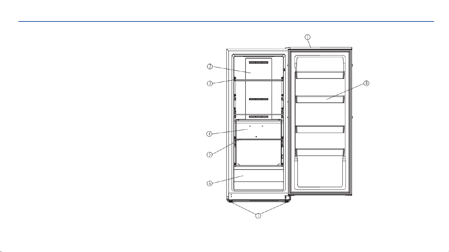
PARTS IDENTIFICATION
1.Door
2.Upper air duct plate
3.Glass shelf I
4.Lower air duct board
5.Glass shelf II
6.Lower drawer
7.Adjustable Feet
8.Door shelf
Page 1
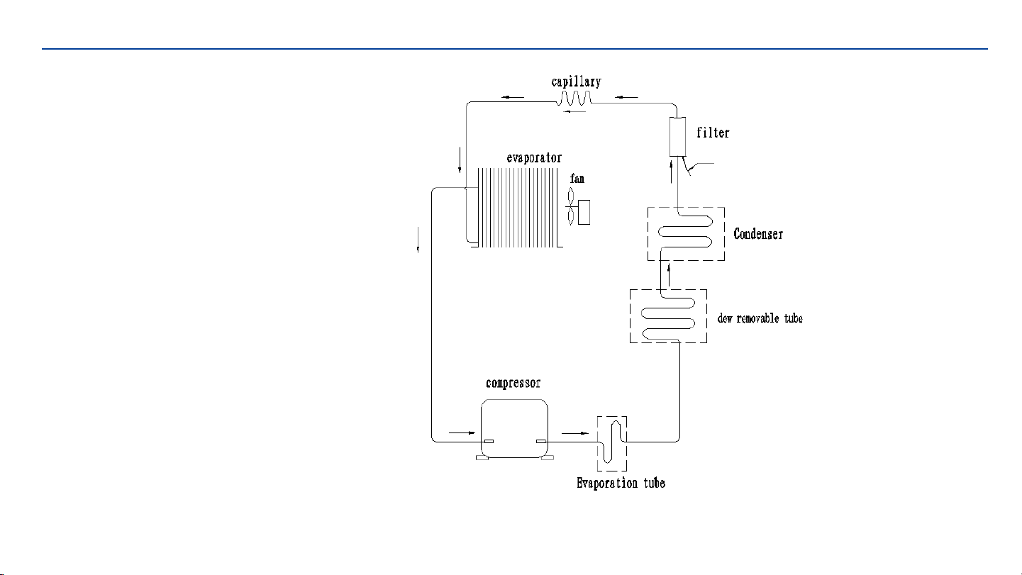
REFRIGERATION CIRCUIT
Basic refrigeration schematic
Page 2

CIRCUIT DIAGRAM Page 3

SAFETY PRECAUTIONS
AFETY REQUIREMENTS
DANGER: Risk of fire or explosion. Flammable refrigerant used. Do not puncture refrigerant tubing.
•Do not use mechanical devices to defrost refrigerator.
•Ensure that servicing is done by factory authorized service personnel, to minimize product damage or safety issues.
•If the power supply cord is damaged, it must be replaced by the manufacturer, its service agent or similar qualified person in order to avoid
hazard.
•Consult repair manual or owner’s guide before attempting to service this product. All safety precautions must be followed.
•Dispose of properly in accordance with federal or local regulations.
•Follow handling instructions carefully.
•Do not store explosive substances such as aerosol cans with a fl ammable propellant in this appliance.
WARNING: Keep ventilation openings, in the appliance enclosure or in the built-in structure, clear of obstruction.
WARNING: Do not use mechanical devices or other means to accelerate the defrosting process, other than those recommended by the
manufacturer.
WARNING: Do not damage the refrigerant circuit.
WARNING: Do not use electrical appliances inside the food storage compartments of the appliance,unless they are of the type recommended
by the manufacturer.
CAUTION: Risk of fire or explosion. Flammable refrigerant used.
CAUTION: Children should be supervised to ensure that they do not play with the appliance.
DANGER: Risk of child entrapment. Before throwing
away an old appliance:
•Remove the door or lid.
•Leave shelves in place so that children may not easily climb inside.
DANGER: Do not add a lock to the door or lid. This can cause child entrapment and harm.
Page 4

SAFETY PRECAUTIONS
SAFETY REQUIREMENTS
This appliance is not intended for use by persons (including children) whose physical, sensory or mental capabilities may be different or
reduced,or who lack experience or knowledge, unless such persons receive supervision or training to operate the appliance by a person
responsible for their safety.
This appliance is intended to be used in household and similar applications such as:
• Staff kitchen areas in shops, offi ces and other working environments;
• Farm houses and by clients in hotels, motels and other residential type environments;
• Bed and breakfast type environments;
• Catering and similar non-retail applications.
GROUNDING INSTRUCTIONS
This appliance must be grounded. Grounding reduces the risk of electrical shock by providing an escape wire for the electrical current.
This appliance has a cord that has a grounding wire with a 3-prong plug. The power cord must beplugged into an outlet that is properly
grounded.
If the outlet is a 2-prong wall outlet, it must bereplaced with a properly grounded 3-prong walloutlet. The serial rating plate indicates the
voltage and frequency the appliance is designed for.
WARNING -Improper use of the grounding plug can result in a risk of electric shock.Consult a qualifi ed electrician or service agent if the
grounding instructions are not completely understood, or if doubt exists as to whether the appliance is properly grounded.
Do not connect your appliance to extension cords or together with another appliance in the same wall outlet. Do not splice the power
cord.
Do not under any circumstances cut or remove the third ground prong from the power cord. Do not use extension cords or ungrounded (two
prongs)adapters.
If the power supply cord is damaged, it must be replaced by the manufacturer, its service agent or similar qualified person in order to avoid
hazard.
Page 5

USING INTRODUCTION
LOCATION
• Two people should be used when moving the appliance.
• Remove interior and exterior packaging prior to installation. Wipe the outside of the appliance with a soft, dry cloth and the inside with a
lukewarm wet cloth.
• Place the appliance on a fl oor that is strong enough to support it when it is fully loaded.
• Do not place the appliance in direct sunlight or near sources of heat, such as a stove or heater,as this can increase electrical consumption.
Extreme cold ambient temperatures may also cause the appliance to perform improperly.
• Do not use the appliance near water, for example in a wet basement or near a sink.
• This appliance is intended for indoor household only. It is not designed for outside installation, including anywhere that is not temperature
controlled such as porches,vehicles, etc.
• Before connecting the appliance to a power source, let it stand upright for approximately 6 hours. This will reduce the possibility of a
malfunction in the cooling system from handling during transportation.
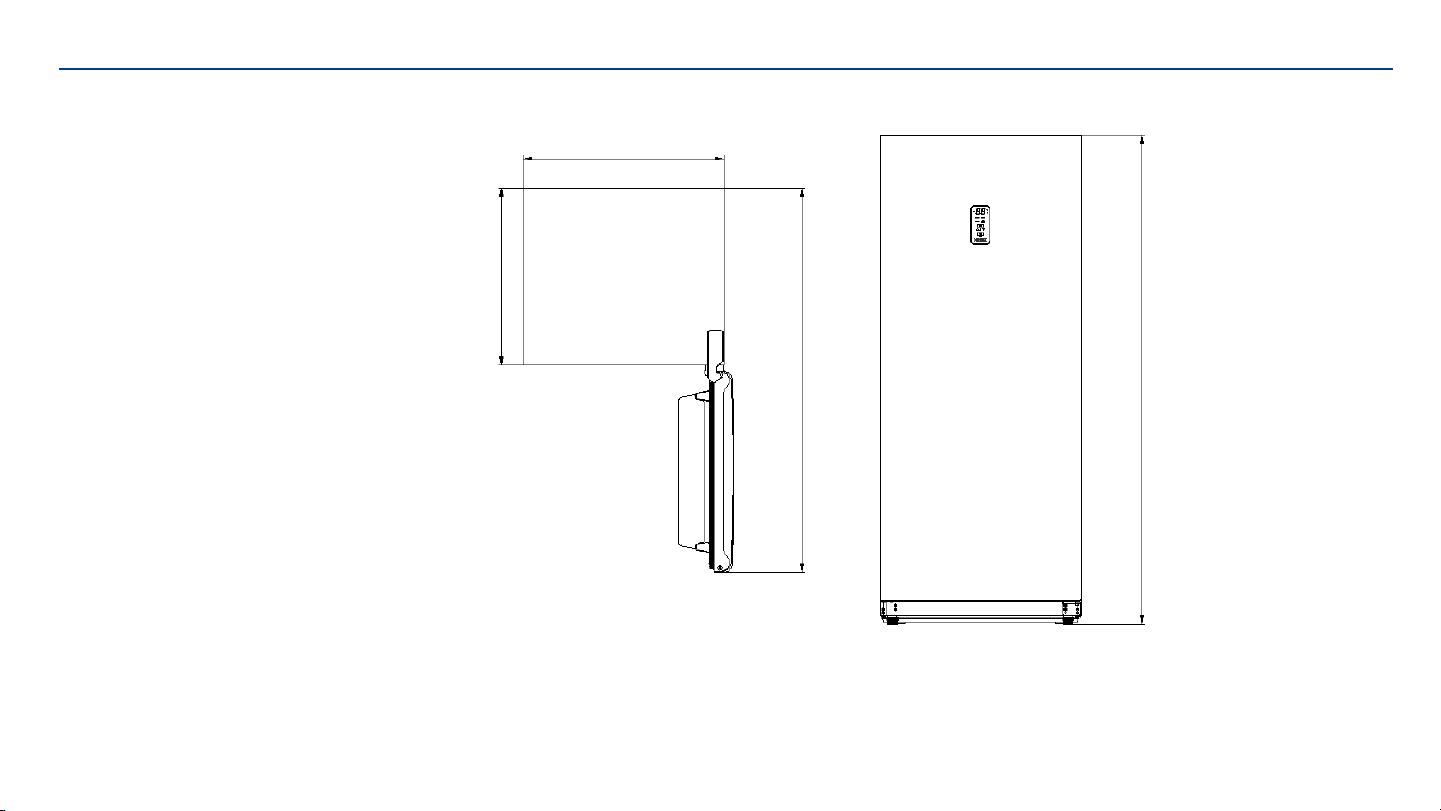
• This appliance is 71.0 cm (27.95 inches) wide by 172.8cm (68.03 inches) high by 70.9 cm(27.89 inches) deep. Make sure that you leave the
minimum amount of space between the appliance and all surrounding walls and vents.Do not cover any of the ventilation openings with any
material as the appliance needs adequate space to breathe.
• Allow 12.7 cm (5 inches) of space between the back, sides and top of the appliance and all adjacent walls.
• This appliance is intended for free-standing installation only and is not intended to be built into a cabinet or counter. Building in this
appliance can cause it to malfunction.
LEVELING INSTRUCTIONS
There are two adjustable legs on the bottom of the appliance that can be turned up or down to ensure that the appliance is level.
1. Turn the leveling leg counter-clockwise as far as it will go, until the top
of the foot is touching the bottom of the chassis.
2. Slowly turn the leveling leg clockwise until theappliance is level.
Page 6
USING INTRODUCTION
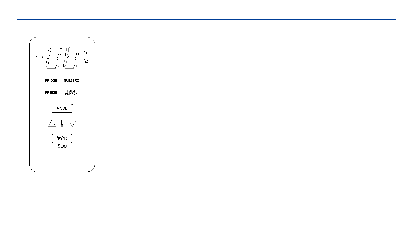
TEMPERATURE SETTING
When the temperature display is display will extinguish automatically after three minutes. When
the display is extinguishing, press the keys to activate it, then key function will start work.
Below operating instruction only applies to the display is unlocked
• Press the arrow buttons to set or adjust the temperature.
• "MODE", the operating mode will change and keep flashing when you press it. If no further
action within 5 seconds, the current setting will take effect. The operating mode switch as
follow: "FRIDGE"—"SUBZERO"—"FREEZE"—"FASTFREEZE"—"FRIDGE“
• " ℉/℃", Tap the key, it will switch between the centigrade and Fahrenheit. The panel will lock
if keep pressing " ℉/℃" for 3 seconds. To unlock it, press " ℉/℃"for 3 seconds.
• TEMPERATURE SCALE
“FRIDGE”:0℃~8℃(32℉~46 ℉)
"SUBZERO":-4℃~-8℃(24 ℉~17 ℉)
"FREEZE":-14℃~-24℃(7 ℉~-11 ℉)
"FASTFREEZE":-18℃~-28℃(0 ℉~-18 ℉)
Page 7
CONTROL PANEL

USING INTRODUCTION
OPEN DOOR ALARM
This appliance is equipped with a door alarm that will sound if the door is left open for more than
3minutes. The alarm will beep and the display will flash continuously until the door is closed.
HANDLE INSTALLATION
The appliance ships with the handle inside the cabinet to protect it
from damage. It must be installed by the end user. The appliance
should be unplugged before installing the handle.
1. Position the handle over the exposed doorhandle posts.
2. Remove the two screws from the side of door
with a screwdriver, insert screws into the handle
bracket, fi x it to the side of door and tighten it
until snug.
Note: The handle may look slightly different based
on the colour of the appliance.
Page 8
USING INTRODUCTION
OUTER DIMENSIONS
Page 9
D625
D1356.5
H1728
W710

DISASSEMBLY COMMON PARTS OF REFRIGERATOR
CARE & MAINTENANCE
CLEANING
Ensure the appliance is unplugged before cleaning.
• To clean the inside of the appliance, use a soft cloth and a solution of a tablespoon of baking soda to one quart
of water or a mild soapsolution or some mild detergent.
• Wash removable shelves in a mild detergent solution, then dry and wipe with a soft cloth.
• Clean the outside with a soft, damp cloth and some mild detergent.
• It is important to keep the area clean where the door seals against the cabinet. Clean this area with a soapy
cloth. Rinse with a damp cloth and let dry.
Note: Do not use cleaners containing ammonia or alcohol on the appliance. Ammonia or alcohol can
damage the appearance of the appliance. Never use any commercial or abrasive cleaners or sharp
objects on any part of the appliance.
Page 10

DISASSEMBLY COMMON PARTS OF REFRIGERATOR
CARE & MAINTENANCE
POWER FAILURE
Most power failures are corrected within a few hours and should not affect the temperature of your
appliance if you minimize the number of times the door is opened. If the power is going to be off for
a longer period of time, take the proper steps to protect your contents.
Note: Wait 3 to 5 minutes before attempting to restart the refrigerator if operation has been interrupted.
DEFROST
This unit is equipped with an automatic defrost function and does not require manual defrosting.Defrost water
from the appliance is channeled into a drip tray located above the compressor. Heat transfer from the compressor
causes the defrost water to evaporate.
VACATION
• Short vacations: Leave the appliance operating during vacations of less than three weeks.
• Long vacations: If the appliance will not be used for several months, remove all items and turn
off the appliance. Clean and dry the interior thoroughly. To prevent odor and mold growth,
leave the door open slightly, blocking it open if necessary.
Page 11

DISASSEMBLY COMMON PARTS OF REFRIGERATOR
CARE & MAINTENANCE
ENERGY SAVING TIP
The appliance should be located in the coolest area of the room, away from heat producing appliances,
and out of direct sunlight. Do not overload the unit or block any ventilation openings.
MOVING
• Remove all items.
• Tape the door shut.
• Be sure the appliance stays secure in the upright position during transportation. Also protect the
outside of the appliance with a blanket or similar item.
• If the appliance is placed on its back or side during transportation, upon reaching the destination, allow it to
remain in its operating position for 6 hours to avoid damage to internal components.
DISPOSAL
This appliance may not be treated as regular household waste, it should be taken to the appropriate waste
collection point for recycling of electrical components. For information on local waste collection points,
contact your local waste removal agency or government offi ce.
Page 12

DISASSEMBLY COMMON PARTS OF REFRIGERATOR Page 13
CARE & MAINTENANCE
ERROR CODES
• E1: The freezer sensor failure
• E2: Freezer defrosting sensor failure
• E3: The freezer sensor failure and freezer
defrosting sensor failure
• C0: Communication failure
• dr: Door opening alarm
• EH: Freezer high temperature
• EL: Freezer low temperature
• H1: The freezer heater failure
DISASSEMBLY COMMON PARTS OF REFRIGERATOR
CARE & MAINTENANCE
Page 14
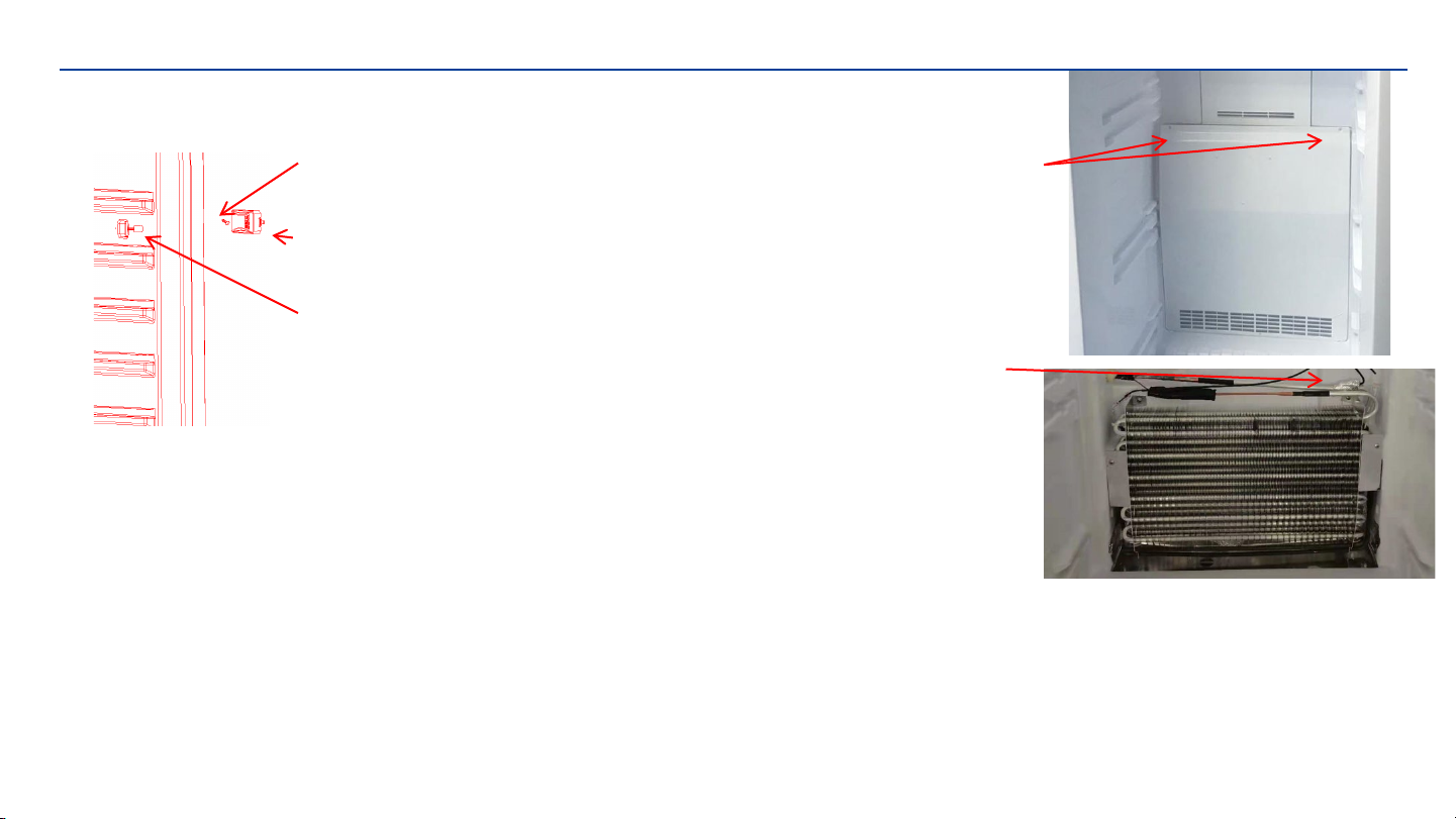
stainless screw
Temperature control
probe cover
Sensor
1.Remove the stainless screw
2.Remove the temperature control probe cover
3.Remove theSensor and replace the Sensor
Lower Air Duct Plate screw
Defrosting sensor
1.Remove the Lower Air Duct Plate screw
2.Remove theDefrosting sensor and replace the
Defrosting sensor
DISASSEMBLY COMMON PARTS OF REFRIGERATOR
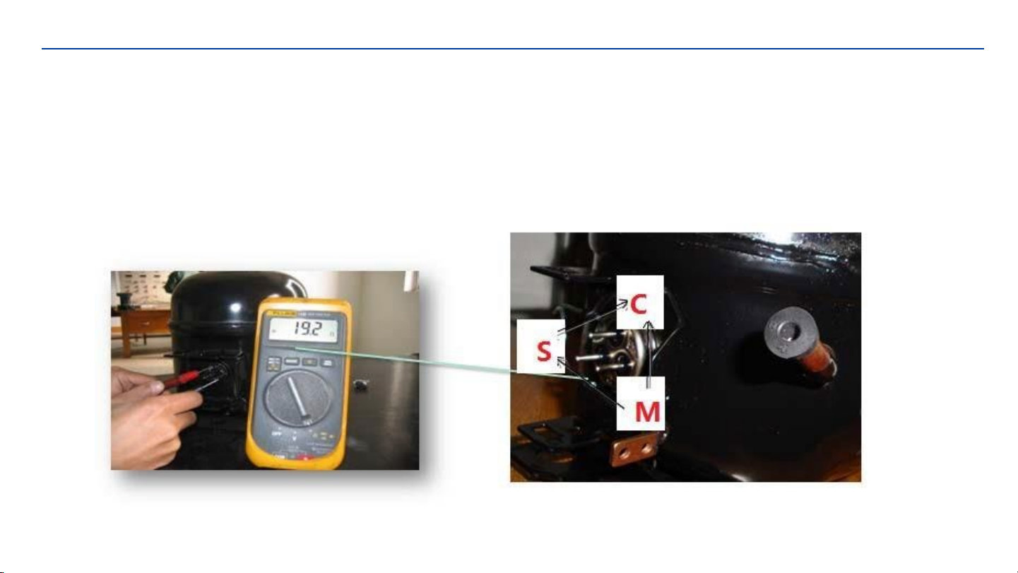
Checking the compressor
Resistance range at 25℃:
Resistance between C and M 5.67~6.93Ω(6.3Ω±10%);
Resistance between C and S 6.03~7.37Ω(6.70Ω±10%);
Resistance between S and M 11.70~14.30Ω(13.00Ω±10%)
Page 15
DISASSEMBLY COMMON PARTS OF REFRIGERATOR
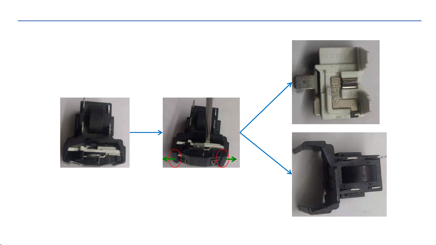
Checking the compressor accessory
Disassemble the PTC starter and Over loaded Protector
1.Remove the PTC and OLP components separately
2.Use a flat-head screwdriver against the hook of the OLP, then press it down
3.When the clip is unhooked, the PTC and OLP can be separated
Page 16
DISASSEMBLY COMMON PARTS OF REFRIGERATOR
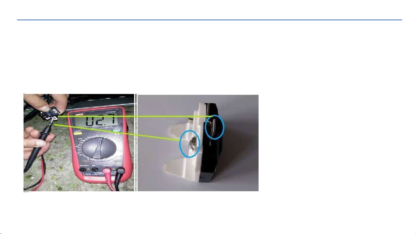
Checking the compressor accessory
Compressor Protector test ——
Use a multi-meter to test the resistance between the two end as the pic show :
If there show 000 or almost 0 then it is OK.
If there is no response then it is broken.
OLP protector : DRB31T61A1
Page 17

DISASSEMBLY COMMON PARTS OF REFRIGERATOR
Checking the compressor accessory
Compressor PTC starter test ——
Use a multi-meter to test the resistance between the two end as the pic show
If there show the number is between about 3.5-5.8 then it is OK.
If there show 000 or no response then it is broken.
After the replacement of the PTC and OLP,
the compressor still does not start.
If there is no exhaust, the compressor is fault.
PTC starter:QPE2-A4R7MD3
Page 18
This manual suits for next models
1
Table of contents
Other Premium levella Refrigerator manuals


